


Ripmax Xcalibur Sports jet
 02-18-2019, 10:04 PM
#2351

Thread Starter
Tone
The horns screw on with self tapping screws, there is a half moon plywood plate in all surfaces. The small looking PK screws are used to screw them on and are more than adequate proved by hundreds of flights. If you iron the film before installing you can see the ply outline
The horns screw on with self tapping screws, there is a half moon plywood plate in all surfaces. The small looking PK screws are used to screw them on and are more than adequate proved by hundreds of flights. If you iron the film before installing you can see the ply outline
 02-18-2019, 11:49 PM
#2352
Tone
The horns screw on with self tapping screws, there is a half moon plywood plate in all surfaces. The small looking PK screws are used to screw them on and are more than adequate proved by hundreds of flights. If you iron the film before installing you can see the ply outline
The horns screw on with self tapping screws, there is a half moon plywood plate in all surfaces. The small looking PK screws are used to screw them on and are more than adequate proved by hundreds of flights. If you iron the film before installing you can see the ply outline
thanks,
Tone
 02-19-2019, 12:54 AM
#2353
The inspectors here wont sign off on the jet here if I only screw them on from one side, that is for sure, even if I tell them it works fine everywhere else :-)
I also bought mine from Lindinger, and a friend also, and we are both missing our 3 mm control clevises. Are they included in your kit ?
I also bought mine from Lindinger, and a friend also, and we are both missing our 3 mm control clevises. Are they included in your kit ?
02-19-2019, 07:08 AM
#2354
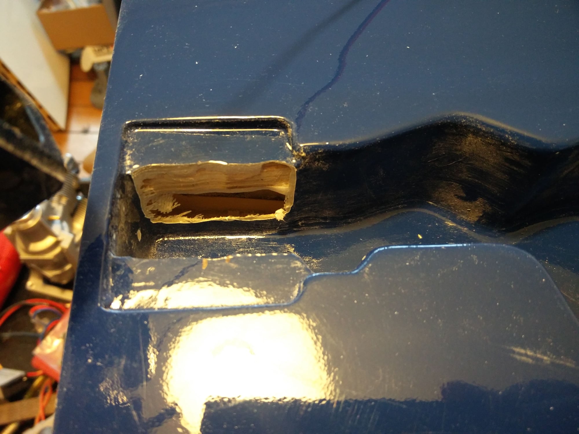
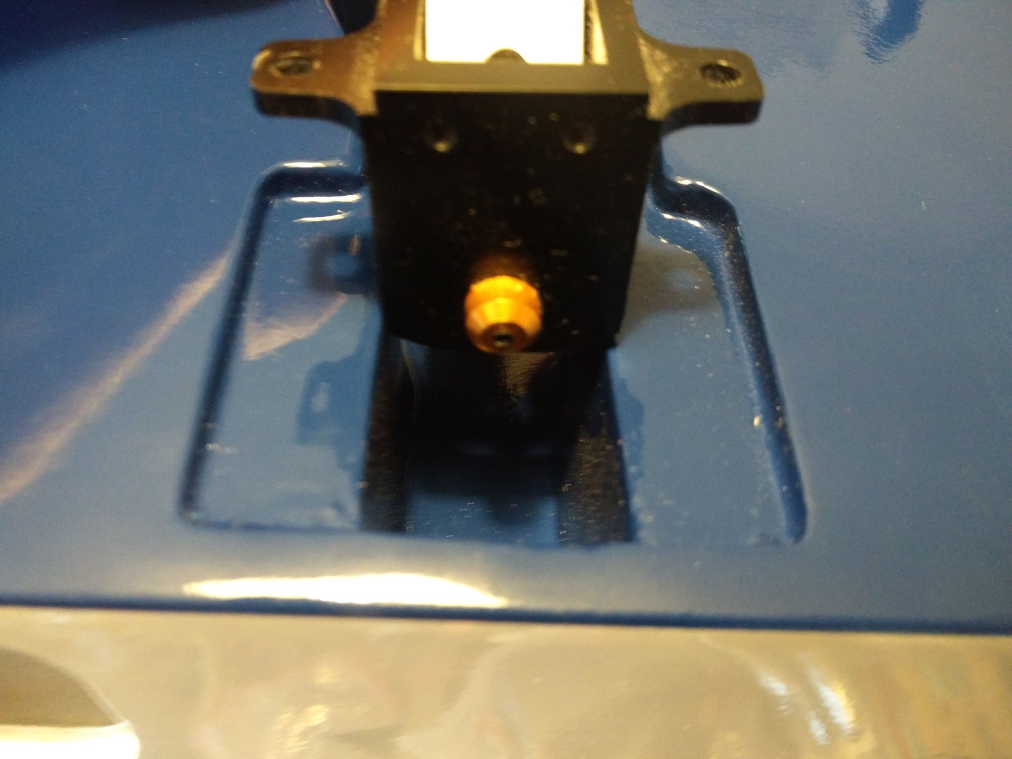
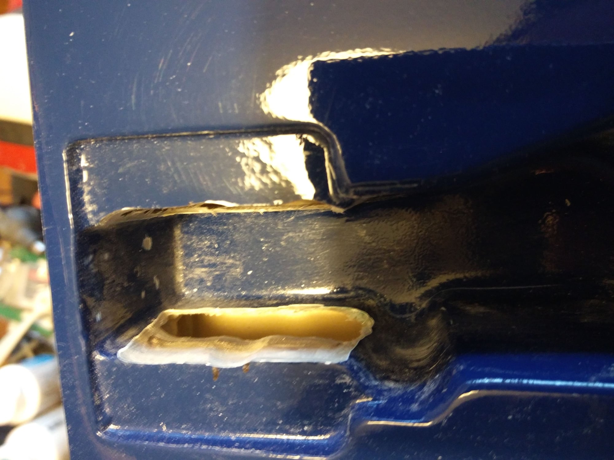
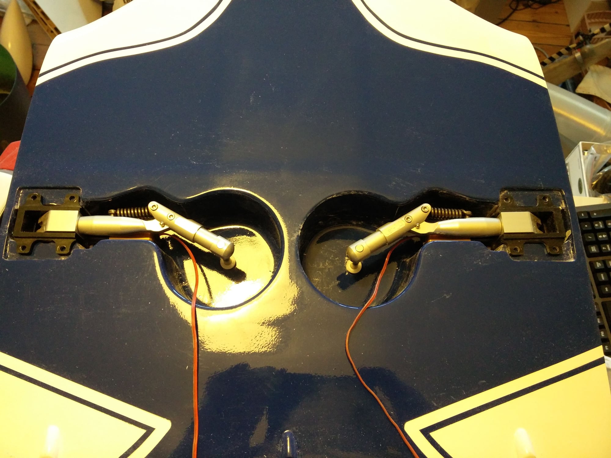
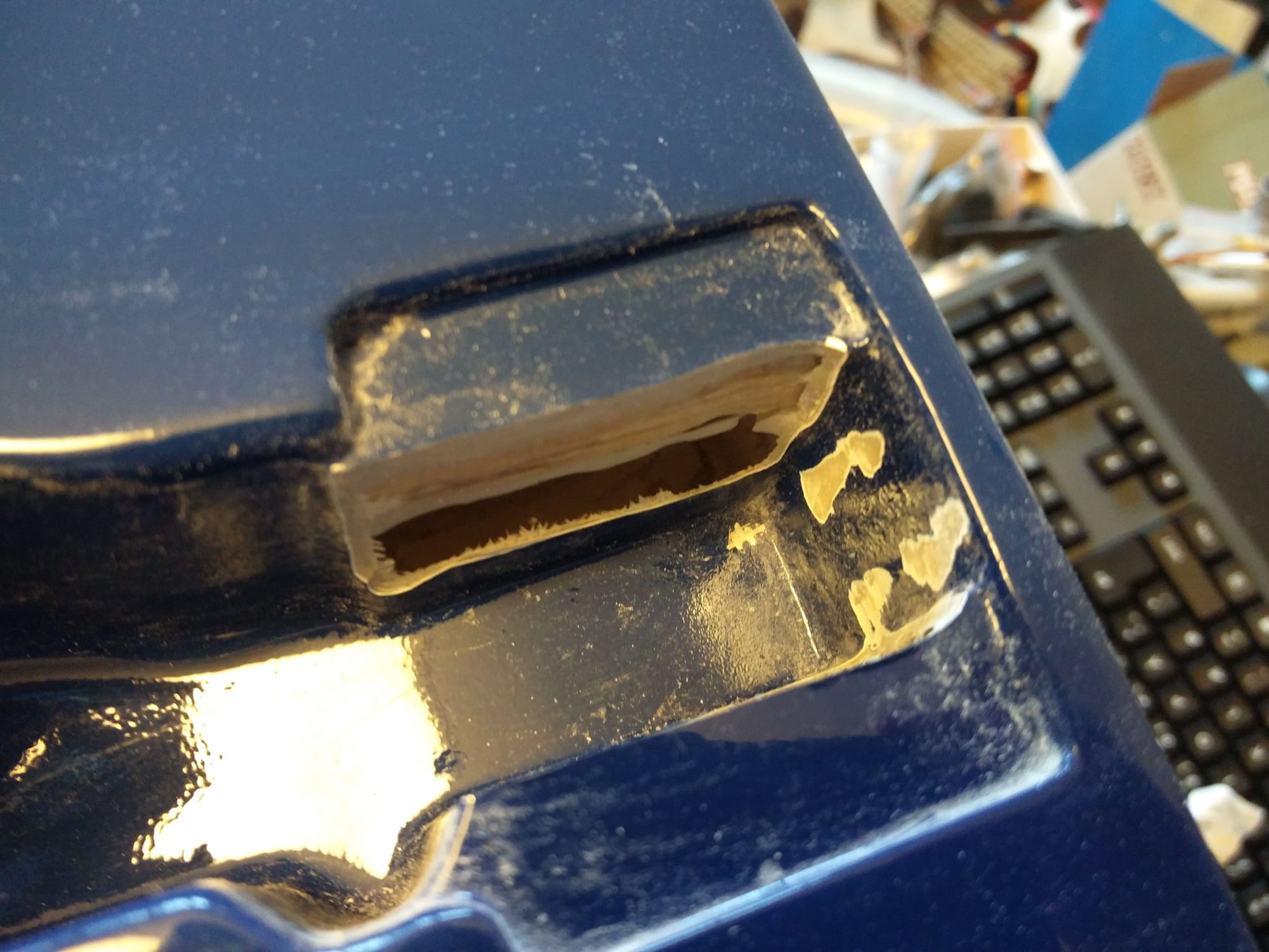
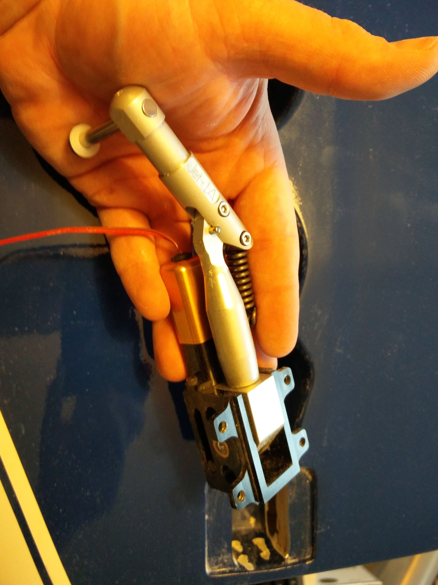
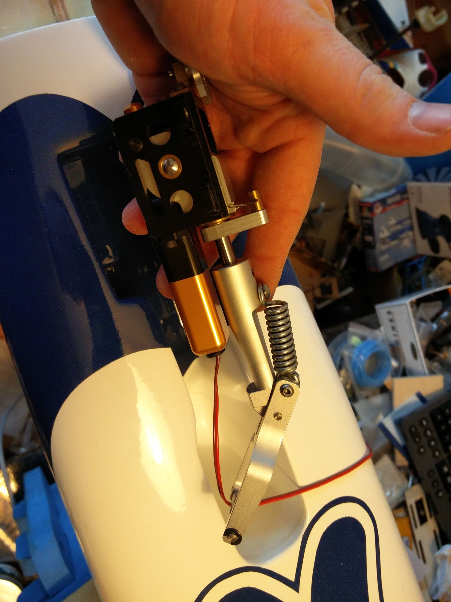
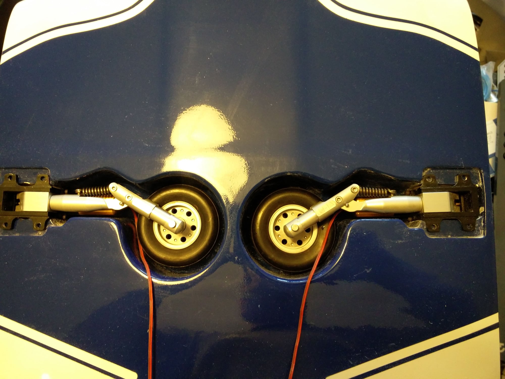
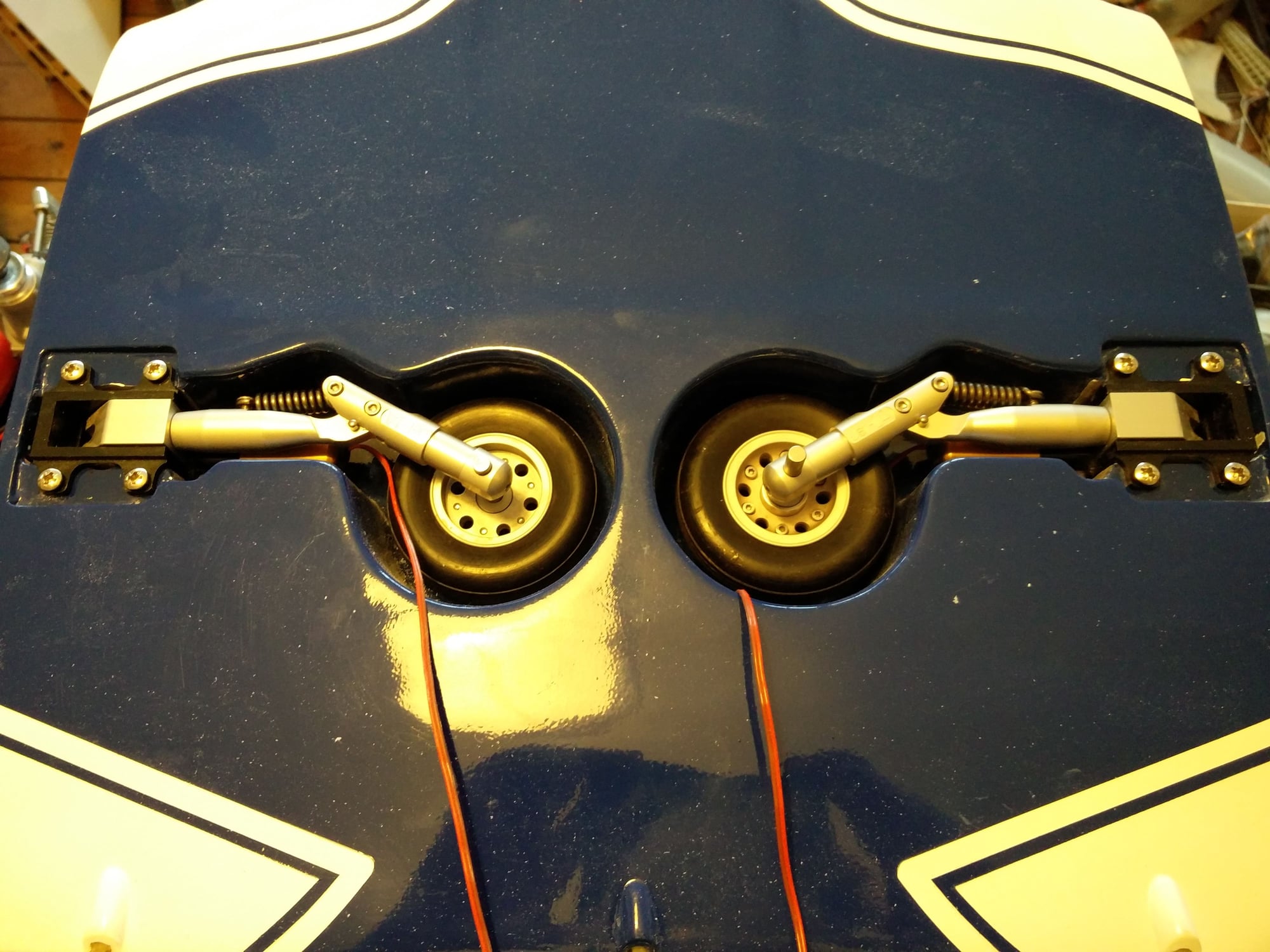
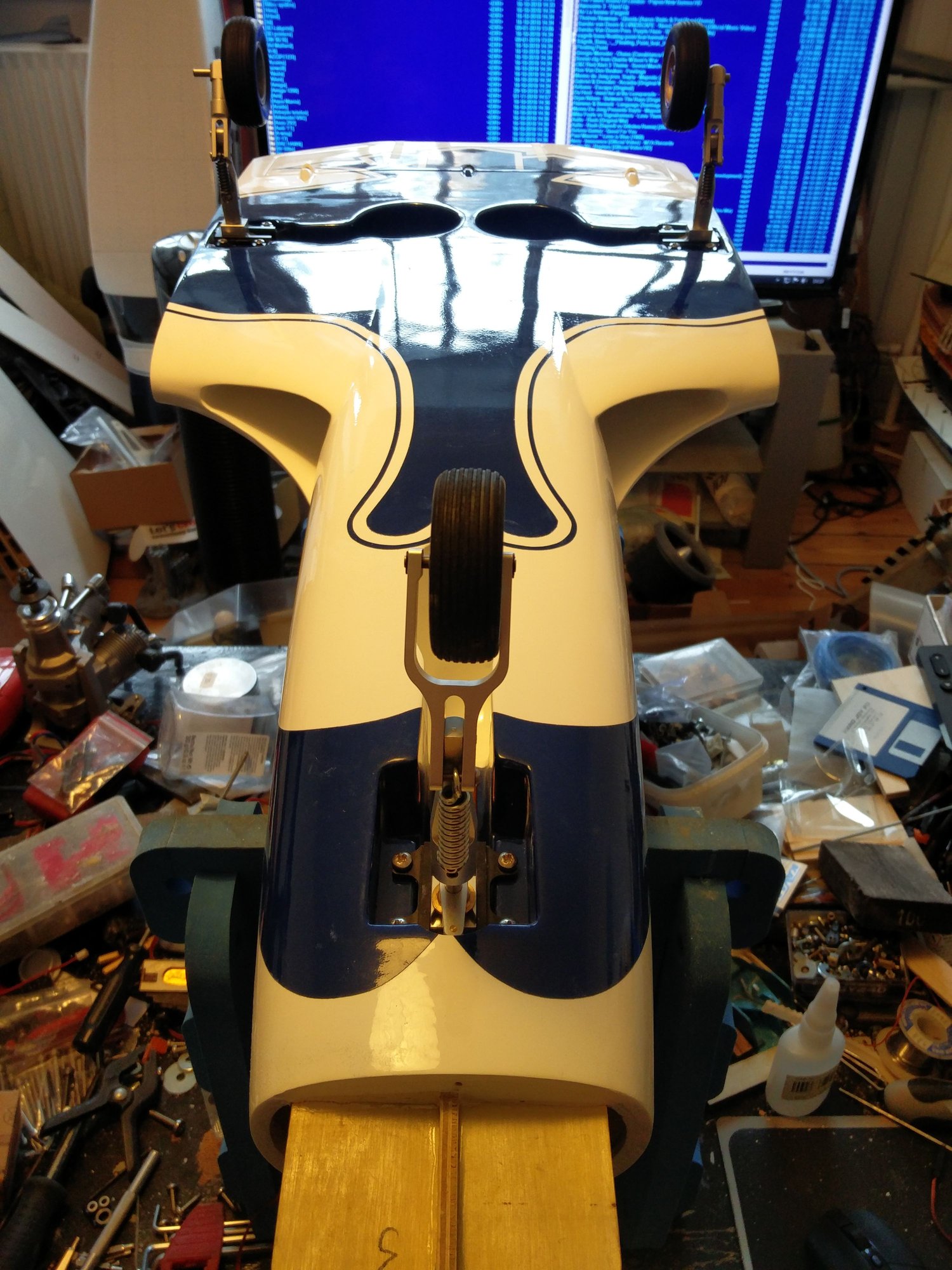
Got my Jet-A1 main retracts today from https://www.jautsch.de/ , so Now I can begin the install.
Im using the original ripmax nosegear. They will be installed in original CYS R2090 retract units :-)
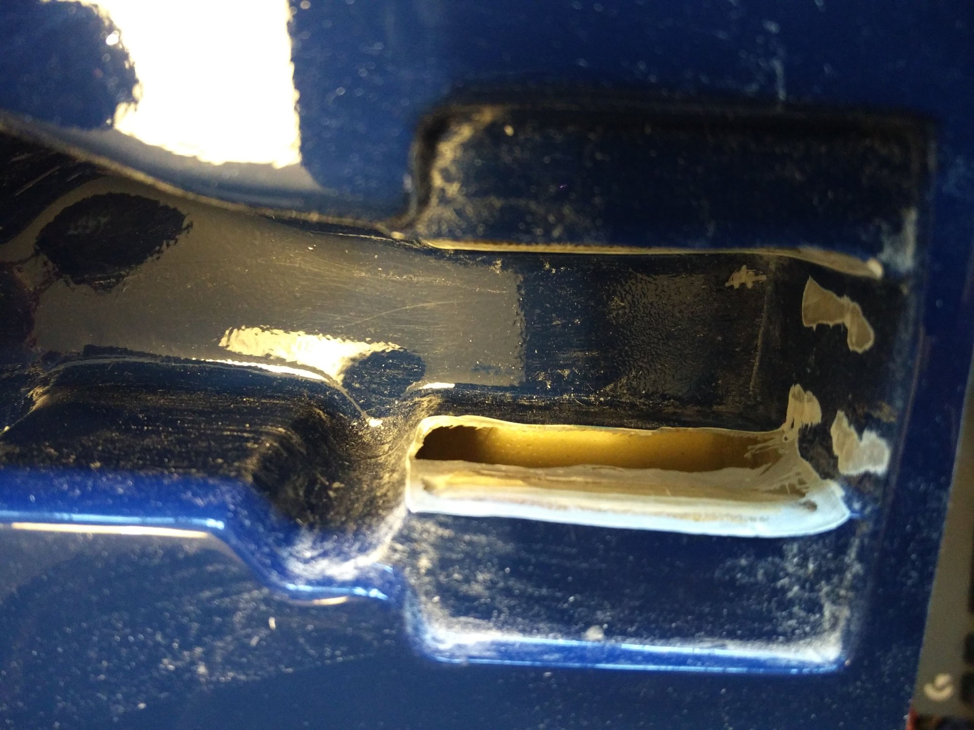
They are 2mm too wide , so I had to dremel out the bays width. The nose gear also has a centering pin, that I had to make room for.
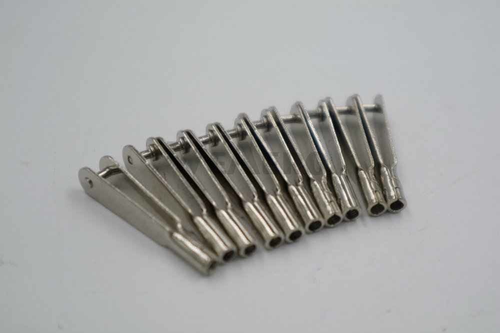
I have removed the original steering system, and have ordered a normal metal horn with 6mm hole in it to fin on the nose leg connecting pin.


Im using the original ripmax nosegear. They will be installed in original CYS R2090 retract units :-)
They are 2mm too wide , so I had to dremel out the bays width. The nose gear also has a centering pin, that I had to make room for.
I have removed the original steering system, and have ordered a normal metal horn with 6mm hole in it to fin on the nose leg connecting pin.
02-19-2019, 08:13 AM
#2355
The inspectors here wont sign off on the jet here if I only screw them on from one side, that is for sure, even if I tell them it works fine everywhere else :-)
I also bought mine from Lindinger, and a friend also, and we are both missing our 3 mm control clevises. Are they included in your kit ?
I also bought mine from Lindinger, and a friend also, and we are both missing our 3 mm control clevises. Are they included in your kit ?
My kit did not come with the 3mm clevis either. I contacted Lindinger and they sent me some threaded 3mm rod and ball links.
thanks,
Tone
Last edited by Agrav8ed; 02-19-2019 at 08:48 AM. Reason: Spelling
02-19-2019, 10:24 AM
#2356
That was nice of them :-)
I just bought some at the local hobby shop.
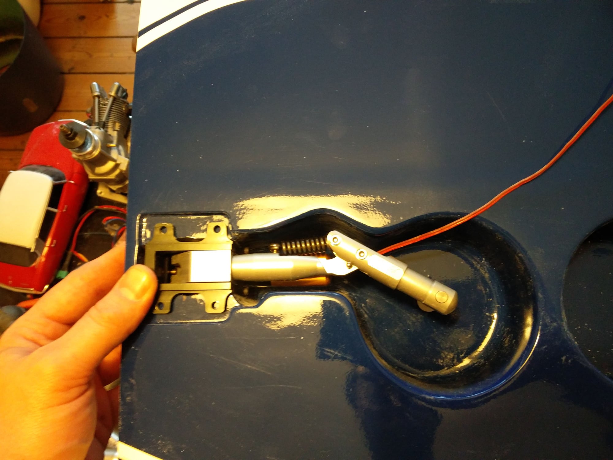
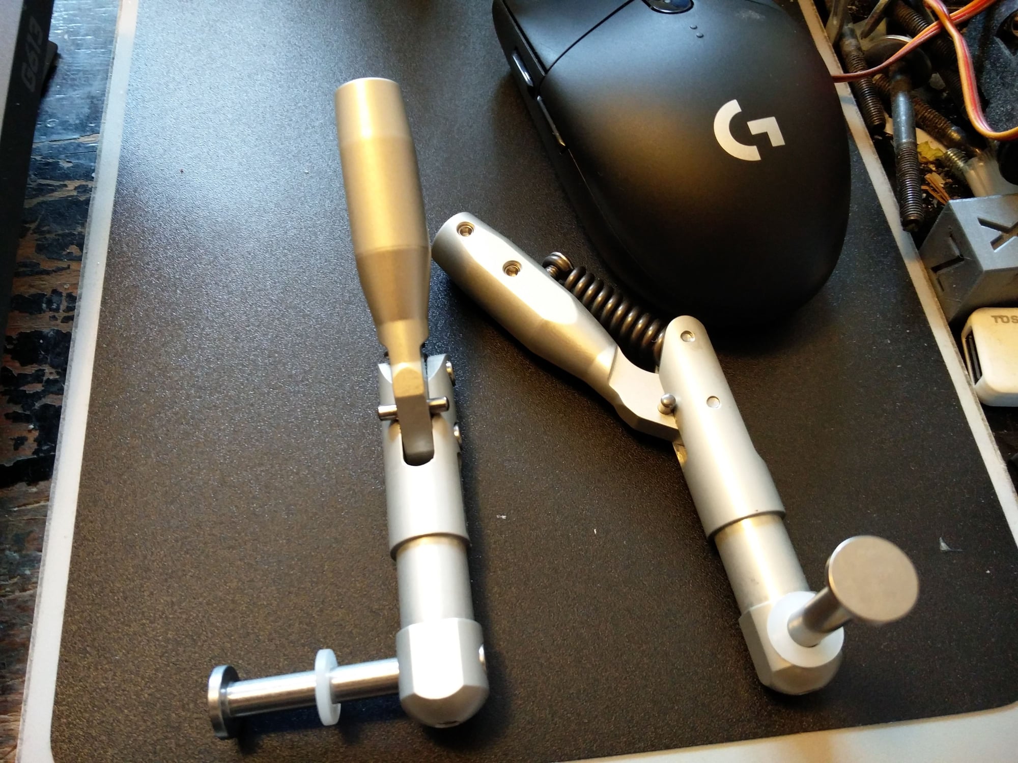
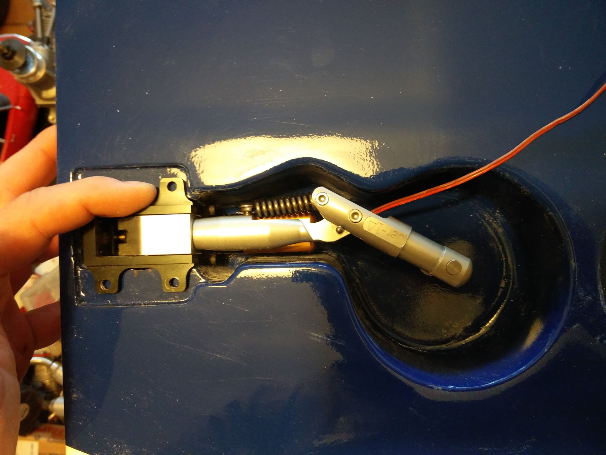
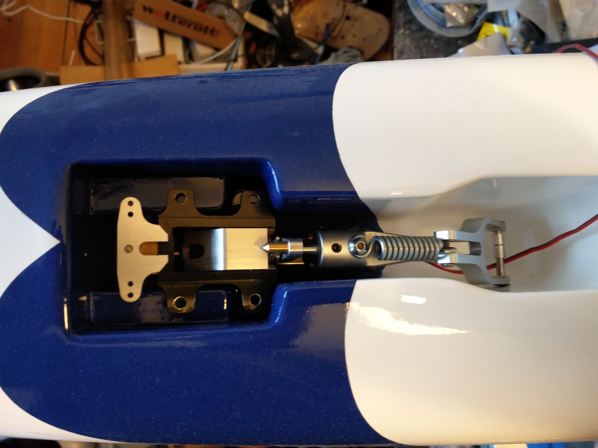
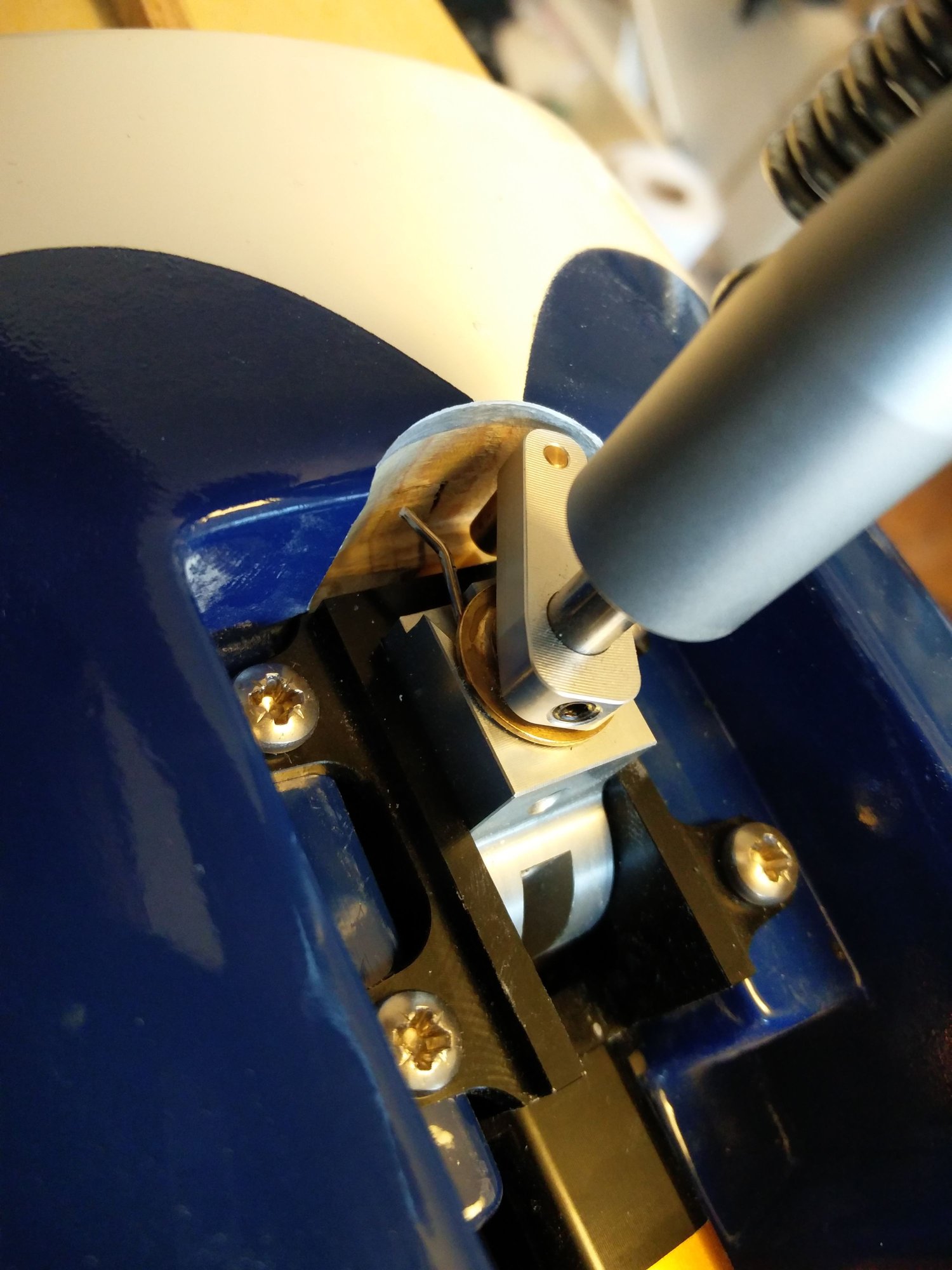
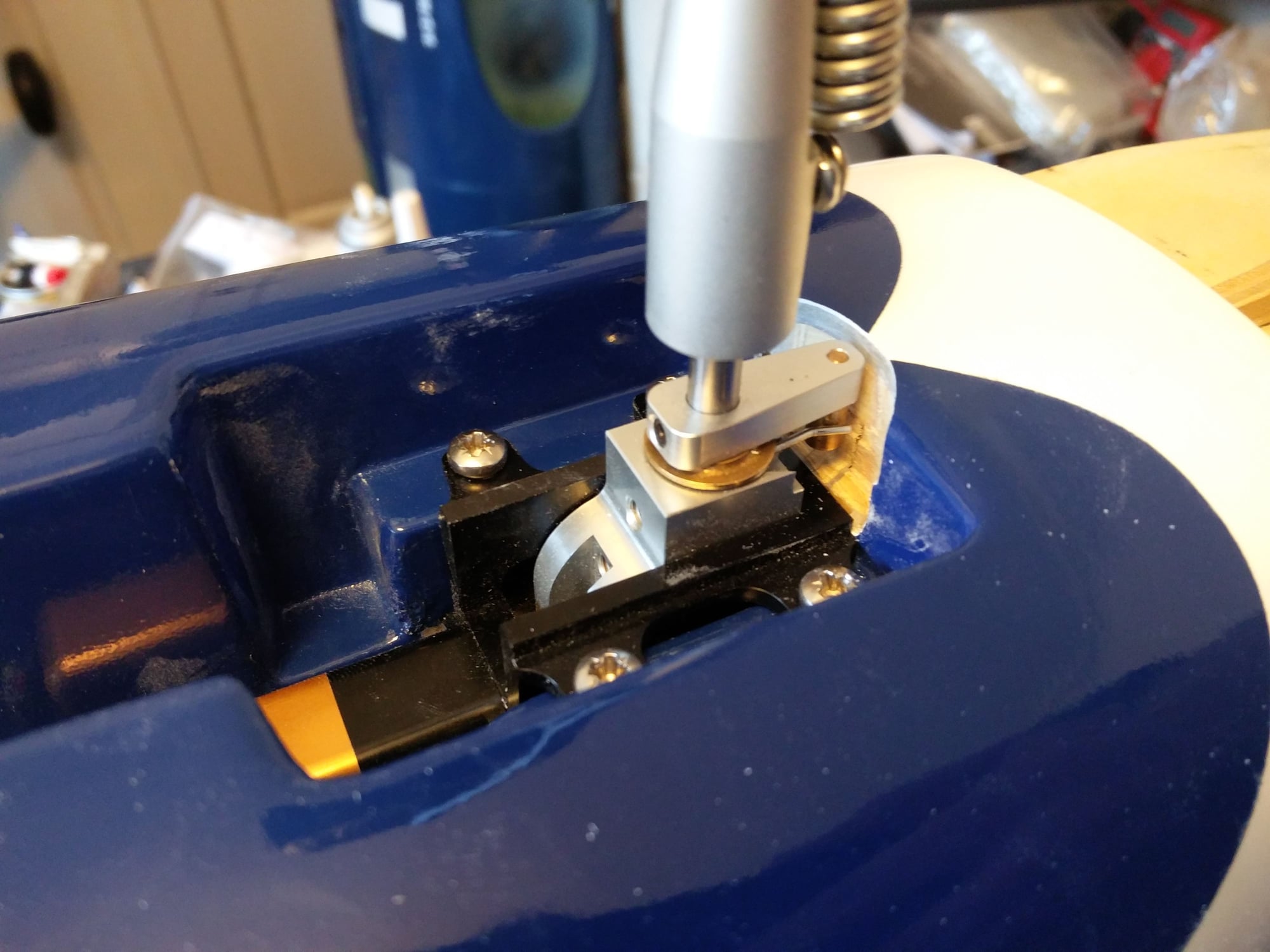
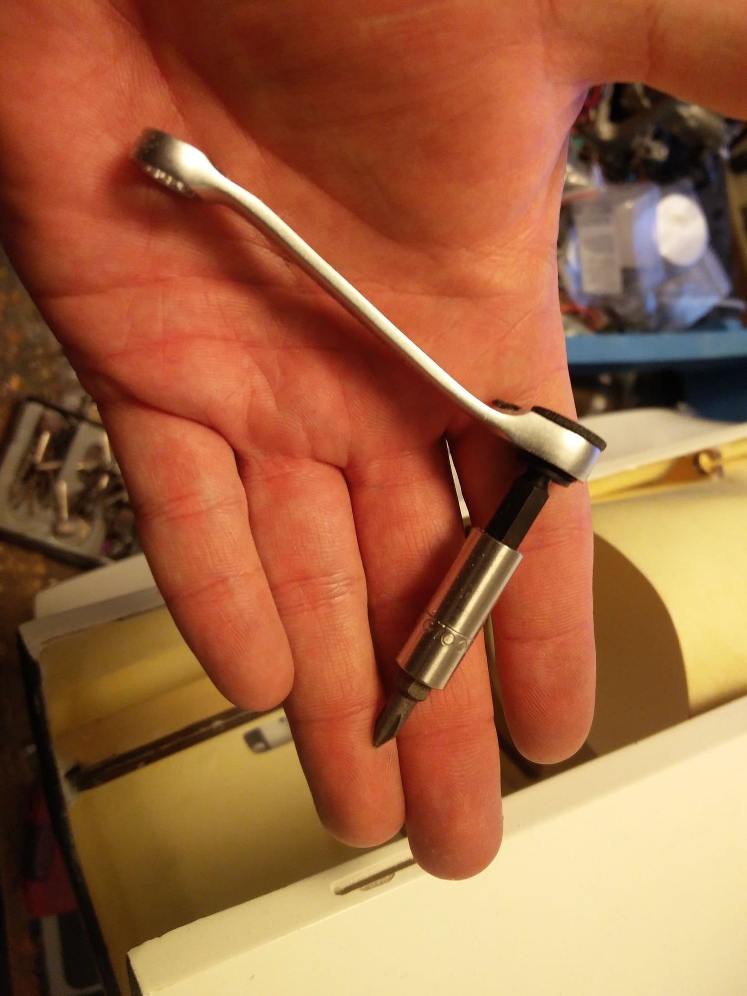
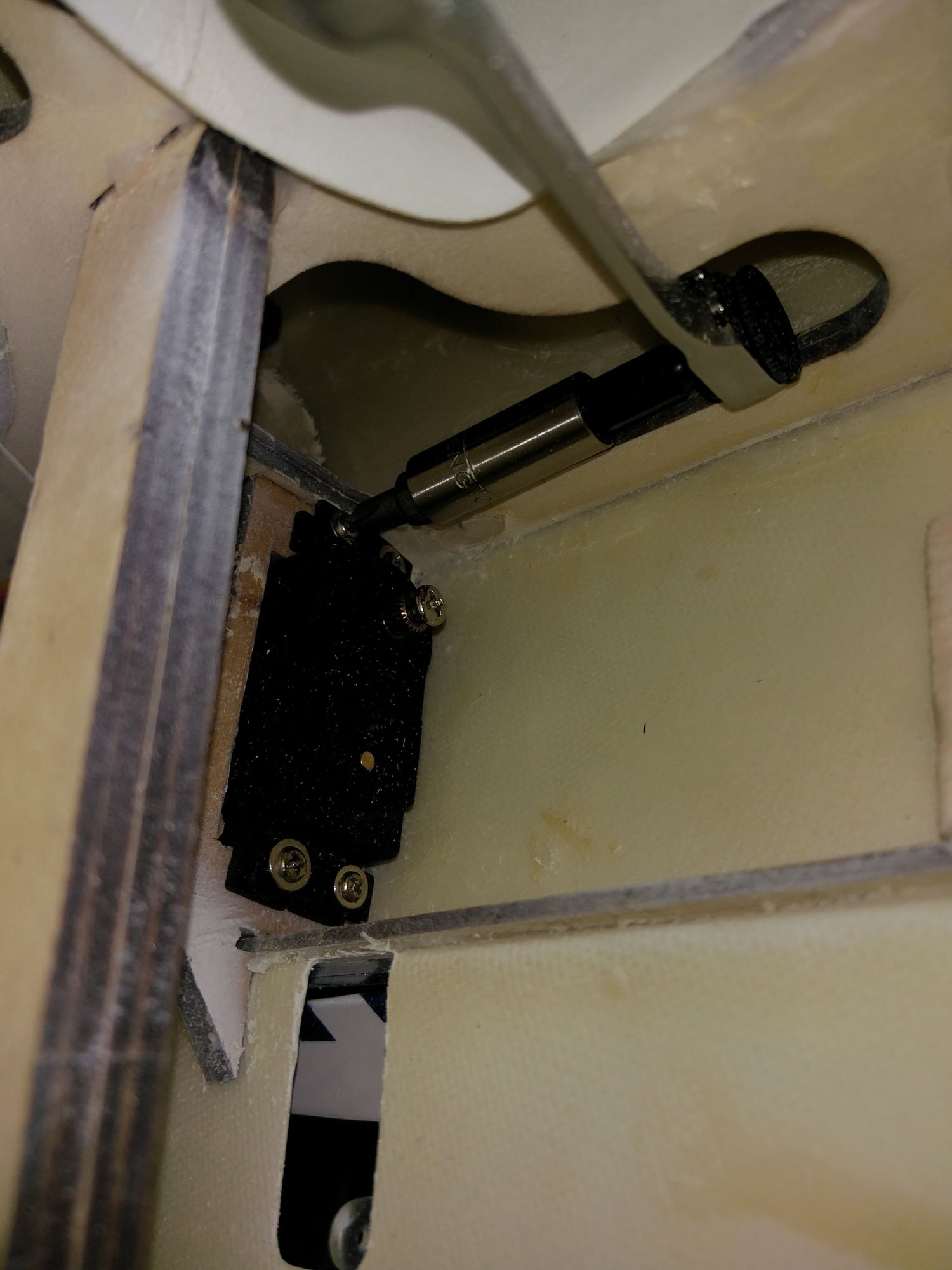
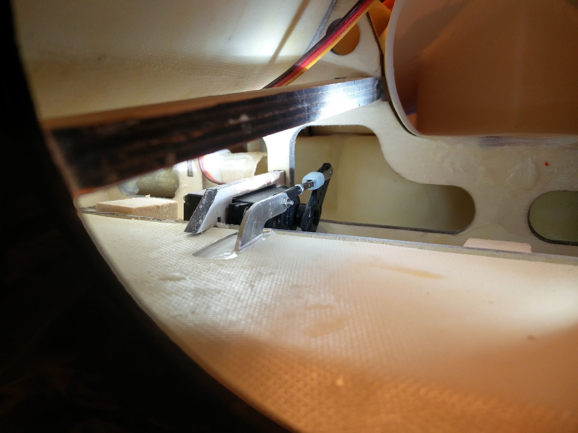
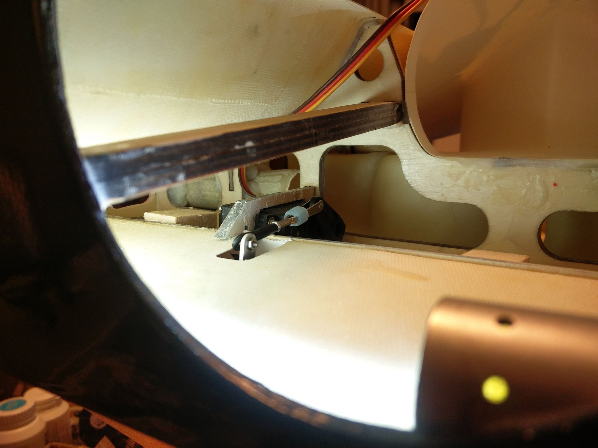
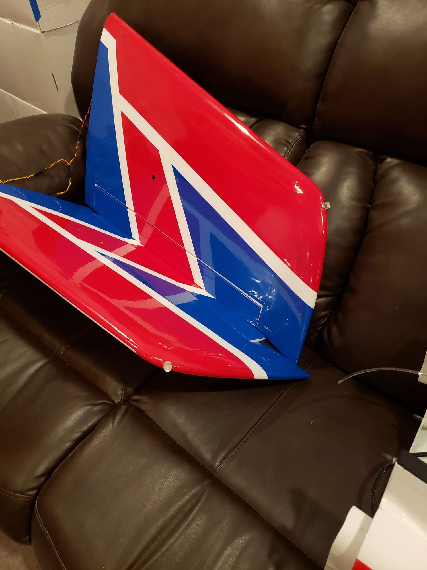
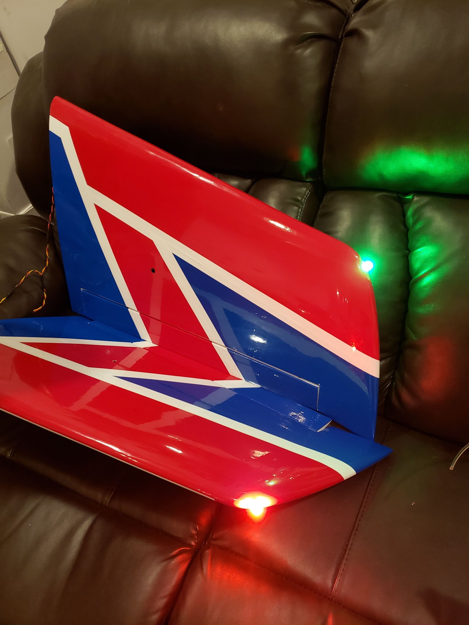
Got my flap/airbrake done.
With the right tools on hand its easy
Man....these big images are annoying.....is there a way to get them to show as thumbnails like before ?
I just bought some at the local hobby shop.
Got my flap/airbrake done.
With the right tools on hand its easy
Man....these big images are annoying.....is there a way to get them to show as thumbnails like before ?
 03-20-2019, 03:42 PM
#2358
When we are mounting the turbine how high does it have to be to match the intake duct? Will all four blocks be enough? The manual states to mount it centerline of the intake duct but the duct is not round so I am a bit confused. Can anyone who has built one give me some advice? I am using a Swiwin 80.
thanks
Tone
thanks
Tone
04-23-2019, 02:46 PM
#2359

My Feedback: (24)
Hi All, I’m finally finishing up my Xcalibur, it’s one of the earlier kits, purchased about 4 years ago. Just a few questions .... Incase there has been any updates from the instruction manual:
Is CG still 160 mm back from the leading edge at the root of the wing panels ?
Control throw for elevator 20mm each way at tip ?
Any up or down thrust shins needed for the turbine mount (I will be using a JetCat P70) ?
Should I use any lubricant on the wheel brake pads ?
Thanks very much !
Bob
Is CG still 160 mm back from the leading edge at the root of the wing panels ?
Control throw for elevator 20mm each way at tip ?
Any up or down thrust shins needed for the turbine mount (I will be using a JetCat P70) ?
Should I use any lubricant on the wheel brake pads ?
Thanks very much !
Bob
04-23-2019, 09:10 PM
#2360
Thread Starter
Bob
With 1/4 tank of fuel make the balance 170mm
20mm is ok for people who like powerful controls, you can go down to 18mm, though the elevator on an Xcalibur is not snappy sharp in control power. You need to fly it to set it how you like.
No additional shim should be needed with a big slugger of a turbine like the P-70. It’s only high efflux velocity units that sometime need a little more down thrust to remove the high speed exhaust gas from the tailplanes lower surface.
i would very lightly grease the wheel surface to reduce grabbing. The brakes are powerful.
06-12-2019, 12:01 PM
#2362
Join Date: Mar 2003
Location: BALLASALLA, CT, UNITED KINGDOM
Posts: 65
Likes: 0
Received 1 Like
on
1 Post
Hi I guess somewhere in the thread must be some setup suggestions for a novice jet pilot ? I have read for hours but not found them yet ! can someone point me to a post which may verify what I need or is the manual setup sufficient to start ?
Many thanks,
Paul.
Many thanks,
Paul.
06-12-2019, 09:10 PM
#2363
Thread Starter
It’s so difficult to give figures not knowing a pilot, will you have someone you know test fly it? If they know you they can discuss your likes.
Xcalibur is sharper on elevator than aileron, so little more expo on elevator than aileron. Balance 170mm with a little fuel.
1mm down elevator with takeoff flap and 3mm with landing flap. As much Flap as you can get ( 80 degrees)
that will I’ll get you close
Xcalibur is sharper on elevator than aileron, so little more expo on elevator than aileron. Balance 170mm with a little fuel.
1mm down elevator with takeoff flap and 3mm with landing flap. As much Flap as you can get ( 80 degrees)
that will I’ll get you close
06-25-2019, 01:21 PM
#2365
Join Date: Mar 2003
Location: BALLASALLA, CT, UNITED KINGDOM
Posts: 65
Likes: 0
Received 1 Like
on
1 Post
It�s so difficult to give figures not knowing a pilot, will you have someone you know test fly it? If they know you they can discuss your likes.
Xcalibur is sharper on elevator than aileron, so little more expo on elevator than aileron. Balance 170mm with a little fuel.
1mm down elevator with takeoff flap and 3mm with landing flap. As much Flap as you can get ( 80 degrees)
that will I�ll get you close
Xcalibur is sharper on elevator than aileron, so little more expo on elevator than aileron. Balance 170mm with a little fuel.
1mm down elevator with takeoff flap and 3mm with landing flap. As much Flap as you can get ( 80 degrees)
that will I�ll get you close
Cheers.
11-13-2019, 09:35 PM
#2367
Here in the US we use Biobor EF anti-microbial additive to take care of just this sort of thing. My turbine colleagues highly recommend it. You probably already figured this out since I am responding to a late 2016 post. But I thought it might be worth the post. There is a product for Kerosene and one for diesel.
https://www.biobor.com/fuel-additive...uel-additives/
This stuff is extremely concentrated. A one pint U.S. bottle treats 640 US gallons.
https://www.biobor.com/fuel-additive...uel-additives/
This stuff is extremely concentrated. A one pint U.S. bottle treats 640 US gallons.
11-26-2019, 06:45 AM
#2368
Join Date: Mar 2003
Location: BALLASALLA, CT, UNITED KINGDOM
Posts: 65
Likes: 0
Received 1 Like
on
1 Post
I have been unable to fly my jet for the past three months due to other matters, but this morning decided to prep it for flight again, it has only had one flight I should add. It was stored with the retracts up and some pressure in the system about 50 psi. The retracts would not come down either by manually pressing the buttons on the valve or from the Tx. After pressurising them back to 110psi they came down but worked intermittently for a while until they obviously freed off and now seem back to normal. Silly question time, is there a best way to preserve the system when not in use ? and is there anything to be used in terms of cylinder lubrication if they are laid up for some time? advice appreciated, thanks.
Paul.
Paul.
11-26-2019, 08:37 AM
#2369
Thread Starter
Paul
Every flying session( first fill only), I put 2 drops (literally that) of Silicon buggy shock oil into the filler valve and then pressurise, this works through the system and reduces the moisture issue. Been doing this for 20 years and all my air retracts continue to hold air! Between 20 and 30WT
Dave
Last edited by Dave Wilshere; 11-26-2019 at 08:39 AM.
11-26-2019, 08:40 AM
#2370
Join Date: Mar 2003
Location: BALLASALLA, CT, UNITED KINGDOM
Posts: 65
Likes: 0
Received 1 Like
on
1 Post
Paul
Every flying session( first fill only), I put 2 drops (literally that) of Silicon buggy shock oil into the filler valve and then pressurise, this works through the system and reduces the moisture issue. Been doing this for 20 years and all my air retracts continue to hold air! Between 20 and 30WT
Dave
Every flying session( first fill only), I put 2 drops (literally that) of Silicon buggy shock oil into the filler valve and then pressurise, this works through the system and reduces the moisture issue. Been doing this for 20 years and all my air retracts continue to hold air! Between 20 and 30WT
Dave
Paul.
12-06-2019, 11:05 PM
#2371
Junior Member
Join Date: Feb 2019
Posts: 9
Likes: 0
Received 0 Likes
on
0 Posts
Hi guys,
Need a bit of advice please.
Excalibur model.. KT 85g2
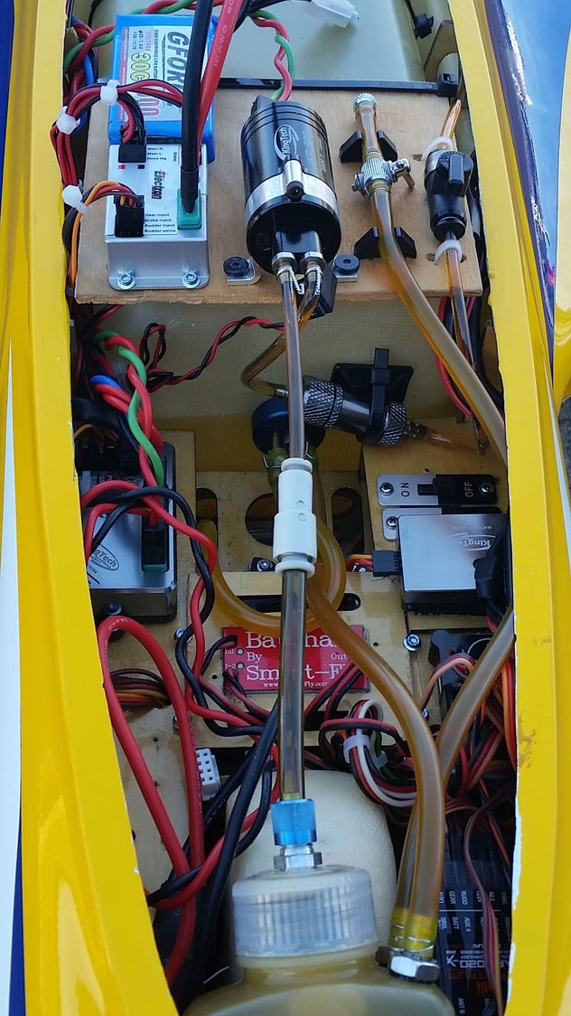
fuel line from CAT air trap to fuel pump issue maybe.
the fitting ID on the CAT is large.. ( like huge)
The fitting on the pump is only 2.5mm ID.
I will therefore need to reduce the fuel line.
I have read that very good article from a few years back on air traps and issues around possible cavitation.
my questions is..
Should the reducer be at the CAT end or the pump input end of the line.
my inclination would be to have it at the pump end ??
to make matters more confusing as I look at all the pictures on the forum I see reducers at both ends.
just dont want to build in a problem from the very start.
many thanks for any information.
Ray
NZ
Need a bit of advice please.
Excalibur model.. KT 85g2
fuel line from CAT air trap to fuel pump issue maybe.
the fitting ID on the CAT is large.. ( like huge)
The fitting on the pump is only 2.5mm ID.
I will therefore need to reduce the fuel line.
I have read that very good article from a few years back on air traps and issues around possible cavitation.
my questions is..
Should the reducer be at the CAT end or the pump input end of the line.
my inclination would be to have it at the pump end ??
to make matters more confusing as I look at all the pictures on the forum I see reducers at both ends.
just dont want to build in a problem from the very start.
many thanks for any information.
Ray
NZ
12-07-2019, 03:32 AM
#2373
My Feedback: (53)

Hi guys,
Need a bit of advice please.
Excalibur model.. KT 85g2
fuel line from CAT air trap to fuel pump issue maybe.
the fitting ID on the CAT is large.. ( like huge)
The fitting on the pump is only 2.5mm ID.
I will therefore need to reduce the fuel line.
I have read that very good article from a few years back on air traps and issues around possible cavitation.
my questions is..
Should the reducer be at the CAT end or the pump input end of the line.
my inclination would be to have it at the pump end ??
to make matters more confusing as I look at all the pictures on the forum I see reducers at both ends.
just dont want to build in a problem from the very start.
many thanks for any information.
Ray
NZ
12-07-2019, 07:17 AM
#2374

Hi guys,
Need a bit of advice please.
Excalibur model.. KT 85g2
fuel line from CAT air trap to fuel pump issue maybe.
the fitting ID on the CAT is large.. ( like huge)
The fitting on the pump is only 2.5mm ID.
I will therefore need to reduce the fuel line.
I have read that very good article from a few years back on air traps and issues around possible cavitation.
my questions is..
Should the reducer be at the CAT end or the pump input end of the line.
my inclination would be to have it at the pump end ??
to make matters more confusing as I look at all the pictures on the forum I see reducers at both ends.
just dont want to build in a problem from the very start.
many thanks for any information.
Ray
NZ
Need a bit of advice please.
Excalibur model.. KT 85g2
fuel line from CAT air trap to fuel pump issue maybe.
the fitting ID on the CAT is large.. ( like huge)
The fitting on the pump is only 2.5mm ID.
I will therefore need to reduce the fuel line.
I have read that very good article from a few years back on air traps and issues around possible cavitation.
my questions is..
Should the reducer be at the CAT end or the pump input end of the line.
my inclination would be to have it at the pump end ??
to make matters more confusing as I look at all the pictures on the forum I see reducers at both ends.
just dont want to build in a problem from the very start.
many thanks for any information.
Ray
NZ
 12-07-2019, 09:35 AM
#2375
Junior Member
Join Date: Feb 2019
Posts: 9
Likes: 0
Received 0 Likes
on
0 Posts
Thanks guys for the information.
some good ideas there..
Thats a neat idea Dansy using a sleeve.... never thought of that.. thanks.
The Festo reducer looks tidy as well.
Dave, thanks for info.. you have confirmed what I was thinking.
cheers
Ray
some good ideas there..
Thats a neat idea Dansy using a sleeve.... never thought of that.. thanks.
The Festo reducer looks tidy as well.
Dave, thanks for info.. you have confirmed what I was thinking.
cheers
Ray