


Xicoy - LG15 Gyro Controlled Brakes
 02-16-2023, 04:49 AM
#526

Upgrading my gear to Electron and plan to use my LG-15...Combed through the thread hoping to find the ER-40 settings, but didn't see any. If anyone knows the specs I'd appreciate it!
 02-16-2023, 05:35 AM
#527
I have had several of these LGCs on JP and Electron gear. All you would need to change is the motor current limits. I assume you have an LGC that allows you to change the current limits (i.e. not locked to a particular set of gear.)
Electron's manual gear operator has three settings, one each for the 30s, 40s and 50s. That being said, one would assume that 40's current limit setting is definitely higher than the 30's, etc. The motors are different. I have one set of gear that will not work on the 30 setting but does work on the 40 setting. So, you are right to assume the current limits are different.
Noone every told me what the any of my gears' current limits should be. So, on the bench, I just started increasing the LGC's current limit settings until the gear worked reliably, and then I added two more units to the LGC's current limit setting. Never had a gear on these controllers fail to go up or come down. But I do disassemble & clean the gear annually even though I never fly off of grass, anymore.
 05-31-2023, 09:51 AM
#530
Junior Member
I'll start by repeating some others, GREAT THREAD!
I'm the new owner of a slightly used T-One Mini.
Came with JP Retracts and Brakes and the JP controller installed.
Also came with a Xicoy LG15.
I was a bit stumped until reading this and Tip22v was very helpful in the order of operations.
I have it all working now.
A few things left me scratching my head so I did some further testing.
They were the difference in retract voltage between the JP and the Xicoy.
And the current vs voltage relationship.
Let's start with the Voltage.
I disassembled the JP unit and did not find any voltage regulators.
Then I set it up for some measurements.
Here's the input voltages vs output voltages (using a bench supply).
INPUT,OUTPUT
8.4, 7.75
8.3, 7.67
8.2, 7.57
....
7.6, 7.02
So the output tracks with the input and always about 0.6v less
Time for the O-Scope.
Ah-Hah!
The JP output is pulsed not constant.
Therefore when you measure it with a DVM out get the average DC voltage!
(Picture a really nice shot of the scope screen here that the forum won't let me post!)
(Pulse on = 18ms)
(Pulse off = 2ms)
The peak is at the "+" input voltage, and it pulses down to near the "-" input.
And therefore the motor experiences the average POWER that this delivers too.
I suspect the pluses may also help the motor start or overcome the stall from the previous direction.
So what is happening on the Xicoy?
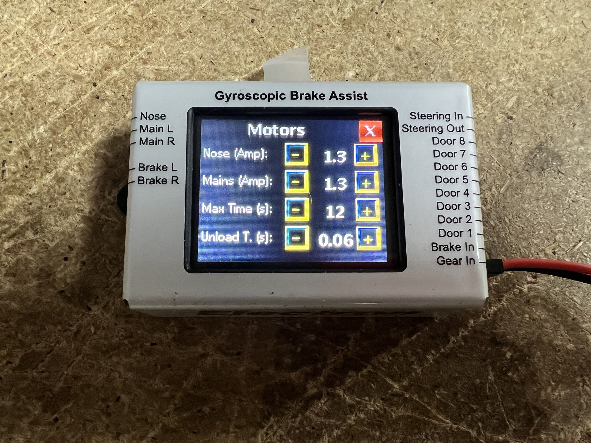
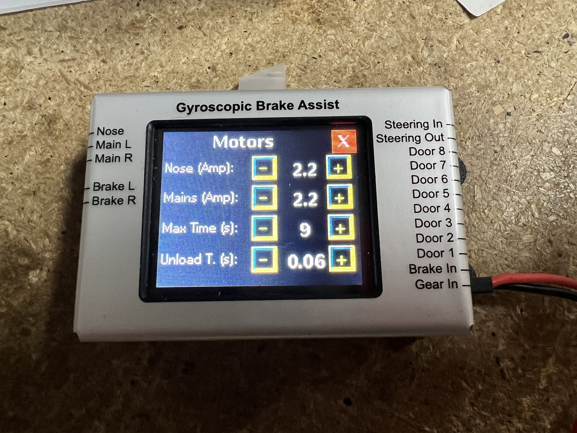
The Xicoy does not pulse and is just constant and at the input voltage.
However, at the end of the movement it does a reverse pulse to back off the motor a "tad".
That's the 0.10s setting called Unload Time.
If you change that to say 0.2s or more, you'll see the motor reverse and move some distance back the direction it came from.
As for Motor Current going up as the Motor Voltage goes down, that is not the case.
It would be if it was like the AC adapter used on your laptop, what's called a smart switching supply or similar.
In this case the JP motor is just a motor, no smarts in there.
So the Current and Voltage are directly proportional.
As for current draw on the JP retract,
Running I saw about 0.6amps to 0.7amps on the retract I was playing with.
And stalled out at 8.4v in I saw about 1amp.
I did order some CC 10A BECs
I'm the new owner of a slightly used T-One Mini.
Came with JP Retracts and Brakes and the JP controller installed.
Also came with a Xicoy LG15.
I was a bit stumped until reading this and Tip22v was very helpful in the order of operations.
I have it all working now.
A few things left me scratching my head so I did some further testing.
They were the difference in retract voltage between the JP and the Xicoy.
And the current vs voltage relationship.
Let's start with the Voltage.
I disassembled the JP unit and did not find any voltage regulators.
Then I set it up for some measurements.
Here's the input voltages vs output voltages (using a bench supply).
INPUT,OUTPUT
8.4, 7.75
8.3, 7.67
8.2, 7.57
....
7.6, 7.02
So the output tracks with the input and always about 0.6v less
Time for the O-Scope.
Ah-Hah!
The JP output is pulsed not constant.
Therefore when you measure it with a DVM out get the average DC voltage!
(Picture a really nice shot of the scope screen here that the forum won't let me post!)
(Pulse on = 18ms)
(Pulse off = 2ms)
The peak is at the "+" input voltage, and it pulses down to near the "-" input.
And therefore the motor experiences the average POWER that this delivers too.
I suspect the pluses may also help the motor start or overcome the stall from the previous direction.
So what is happening on the Xicoy?
The Xicoy does not pulse and is just constant and at the input voltage.
However, at the end of the movement it does a reverse pulse to back off the motor a "tad".
That's the 0.10s setting called Unload Time.
If you change that to say 0.2s or more, you'll see the motor reverse and move some distance back the direction it came from.
As for Motor Current going up as the Motor Voltage goes down, that is not the case.
It would be if it was like the AC adapter used on your laptop, what's called a smart switching supply or similar.
In this case the JP motor is just a motor, no smarts in there.
So the Current and Voltage are directly proportional.
As for current draw on the JP retract,
Running I saw about 0.6amps to 0.7amps on the retract I was playing with.
And stalled out at 8.4v in I saw about 1amp.
I did order some CC 10A BECs
Last edited by Catmanrc; 05-31-2023 at 12:07 PM.
05-31-2023, 01:40 PM
#531
Thread Starter
I'll start by repeating some others, GREAT THREAD!
I'm the new owner of a slightly used T-One Mini.
Came with JP Retracts and Brakes and the JP controller installed.
Also came with a Xicoy LG15.
I was a bit stumped until reading this and Tip22v was very helpful in the order of operations.
I have it all working now.
A few things left me scratching my head so I did some further testing.
They were the difference in retract voltage between the JP and the Xicoy.
And the current vs voltage relationship.
Let's start with the Voltage.
I disassembled the JP unit and did not find any voltage regulators.
Then I set it up for some measurements.
Here's the input voltages vs output voltages (using a bench supply).
INPUT,OUTPUT
8.4, 7.75
8.3, 7.67
8.2, 7.57
....
7.6, 7.02
So the output tracks with the input and always about 0.6v less
Time for the O-Scope.
Ah-Hah!
The JP output is pulsed not constant.
Therefore when you measure it with a DVM out get the average DC voltage!
(Picture a really nice shot of the scope screen here that the forum won't let me post!)
(Pulse on = 18ms)
(Pulse off = 2ms)
The peak is at the "+" input voltage, and it pulses down to near the "-" input.
And therefore the motor experiences the average POWER that this delivers too.
I suspect the pluses may also help the motor start or overcome the stall from the previous direction.
So what is happening on the Xicoy?
The Xicoy does not pulse and is just constant and at the input voltage.
However, at the end of the movement it does a reverse pulse to back off the motor a "tad".
That's the 0.10s setting called Unload Time.
If you change that to say 0.2s or more, you'll see the motor reverse and move some distance back the direction it came from.
As for Motor Current going up as the Motor Voltage goes down, that is not the case.
It would be if it was like the AC adapter used on your laptop, what's called a smart switching supply or similar.
In this case the JP motor is just a motor, no smarts in there.
So the Current and Voltage are directly proportional.
As for current draw on the JP retract,
Running I saw about 0.6amps to 0.7amps on the retract I was playing with.
And stalled out at 8.4v in I saw about 1amp.
I did order some CC 10A BECs
 . -Tom
06-05-2023, 05:53 AM
. -Tom
06-05-2023, 05:53 AM
#533
Thread Starter
isn�t cycling ON/OFF how switching regulators work? The difference here is the the average output voltage is not stabilized at a particular voltage but instead varies based on the input voltage.
06-05-2023, 06:11 AM
#534
Junior Member
Input voltage is switched on/off and then filtered through a circuit to produce true DC at the desired level.
They can step up the voltage or step it down.
Called Buck or Boost modes.
The main differences here being that a switching supply switches at much higher frequencies.
Like 20,000 up to 2,000,000 cycles per second, or Hertz.
The JP unit is switching at 50 Hertz (1 / 0.020s)
And it is is not filtered to be true DC.
But goes directly to the motor.
And on the JP, the peak of the ON pulses are at the input voltage.
So if your JP input is at say 7.8V then the average voltage to the motor is
7.8 times 0.90 and roughly 7V
I like your solution for the Xicoy using the regulator.
I plan to do the same.
Once I get enough posts on the forum I'll share some Scope pics!
Chris
06-05-2023, 07:26 AM
#535
Thread Starter
Yes, switching regulators work in a similar manner.
Input voltage is switched on/off and then filtered through a circuit to produce true DC at the desired level.
They can step up the voltage or step it down.
Called Buck or Boost modes.
The main differences here being that a switching supply switches at much higher frequencies.
Like 20,000 up to 2,000,000 cycles per second, or Hertz.
The JP unit is switching at 50 Hertz (1 / 0.020s)
And it is is not filtered to be true DC.
But goes directly to the motor.
And on the JP, the peak of the ON pulses are at the input voltage.
So if your JP input is at say 7.8V then the average voltage to the motor is
7.8 times 0.90 and roughly 7V
I like your solution for the Xicoy using the regulator.
I plan to do the same.
Once I get enough posts on the forum I'll share some Scope pics!
Chris
06-06-2023, 11:54 AM
#536
Junior Member
Tom, need some guidance.
This is a T-One Mini so just a nose door.
If I have the door say closed on Step 1 and Open on Steps 2-8
Then when putting the gear down it opens during step 2, or starting with step 2
But on gear up it closes during step 1
From the earlier posts is the best practice to spread out the overall Up/Down over most or all the steps?
06-06-2023, 03:15 PM
#537
Thread Starter
Tom, need some guidance.
This is a T-One Mini so just a nose door.
If I have the door say closed on Step 1 and Open on Steps 2-8
Then when putting the gear down it opens during step 2, or starting with step 2
But on gear up it closes during step 1
From the earlier posts is the best practice to spread out the overall Up/Down over most or all the steps?
This is a T-One Mini so just a nose door.
If I have the door say closed on Step 1 and Open on Steps 2-8
Then when putting the gear down it opens during step 2, or starting with step 2
But on gear up it closes during step 1
From the earlier posts is the best practice to spread out the overall Up/Down over most or all the steps?
if I understand your question correct, yes you should spread open/close across many steps.
Last edited by Tip22v; 06-06-2023 at 03:18 PM.
06-06-2023, 06:11 PM
#538
Thread Starter
start at Gear Up, doors closed
step 1 - doors open, step time 1.5s
step 2 - step time .4s
step 3 - step time .1s
step 4 - step time .1s
step 5 - Gear Down, step time .1s
step 6 - step time .1s
step 7 - step time .1s
step 8 - step time 1.0s
end at Gear Down, step time 1.5 s


