


Turbine Conversion Of Freewing 90mm Eurofighter
 05-03-2023, 05:00 PM
#26

Thread Starter
My Feedback: (20)
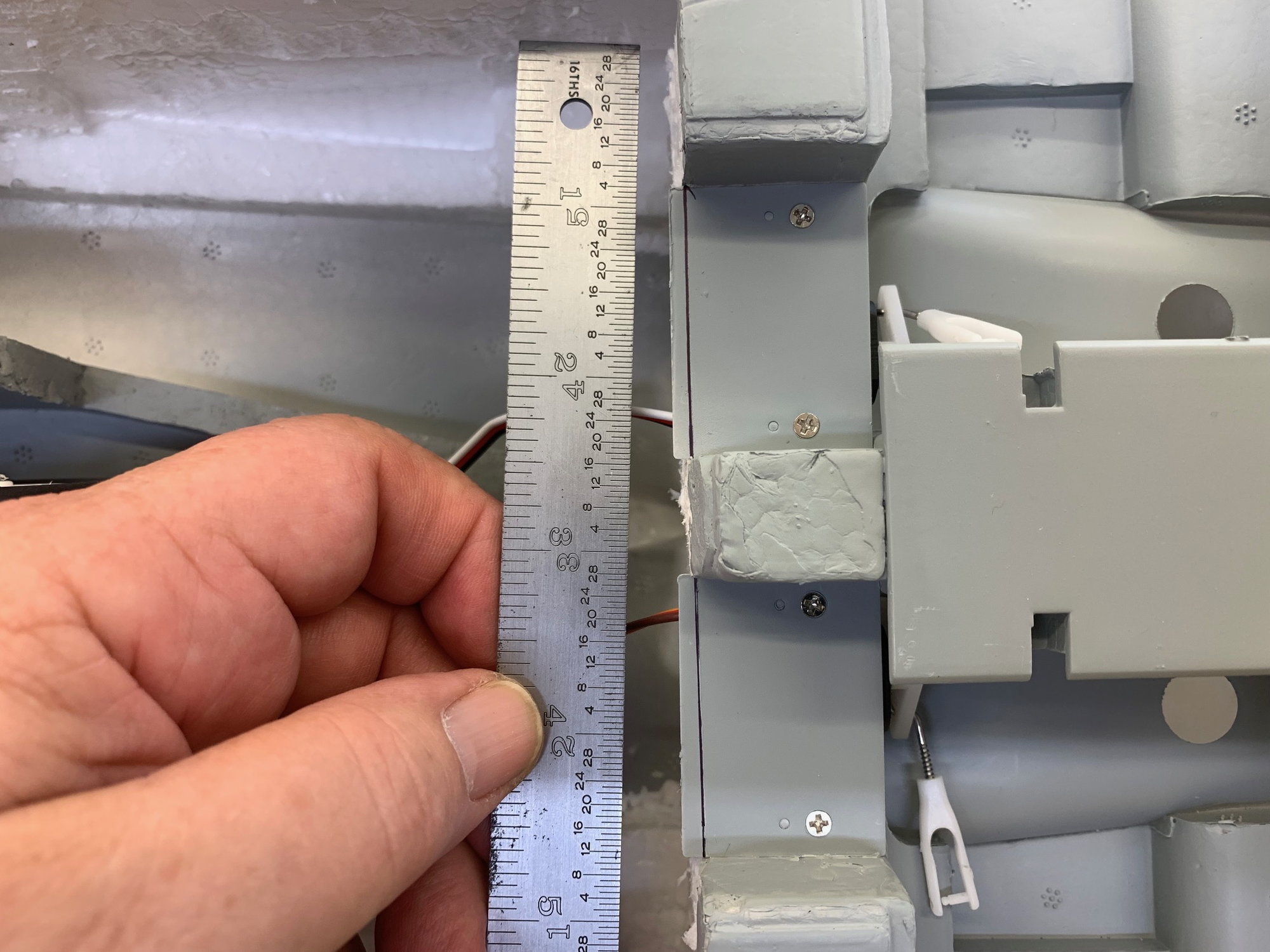
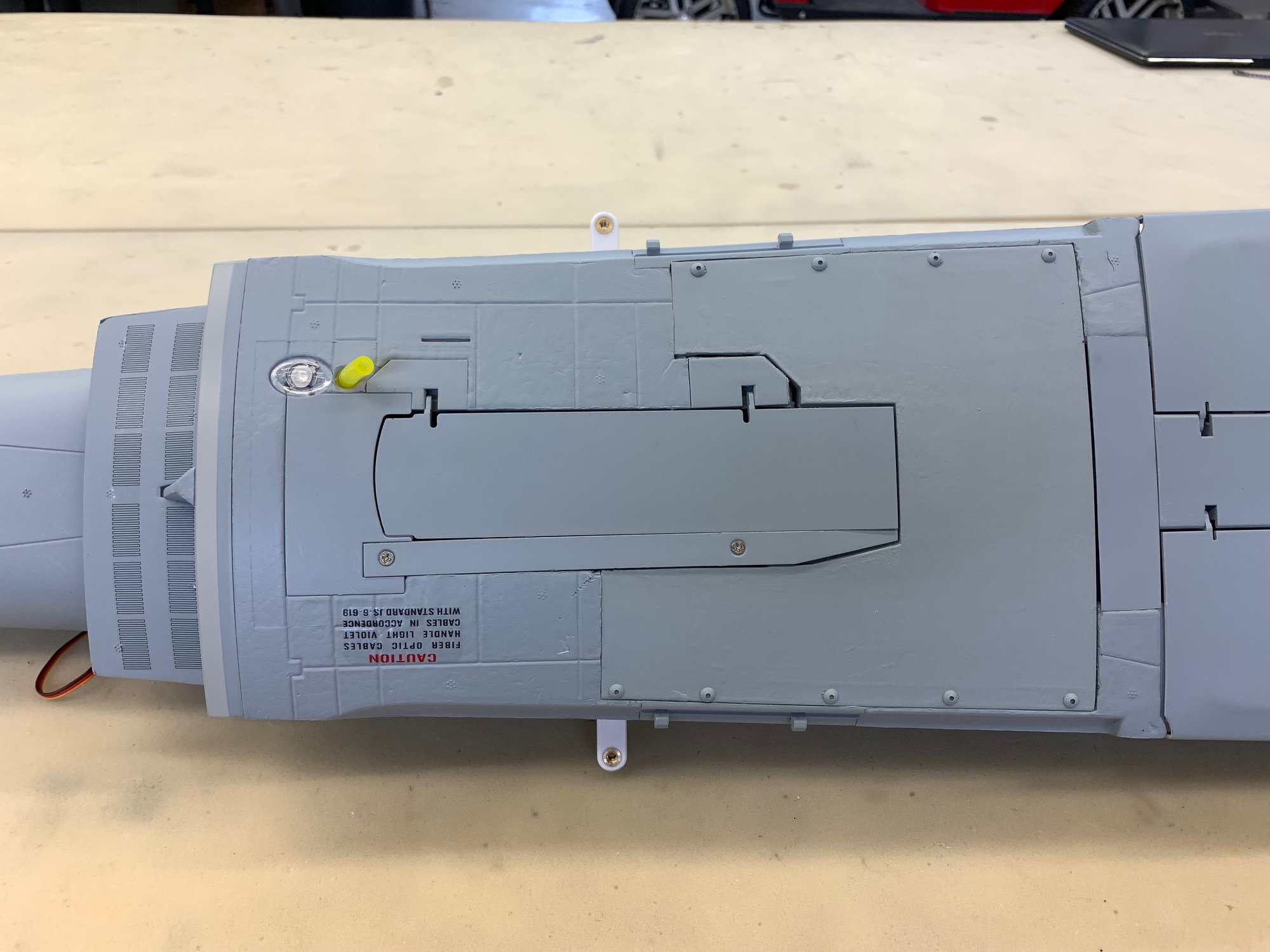
Main Gear Door Servos and Main Tank Screws installed.
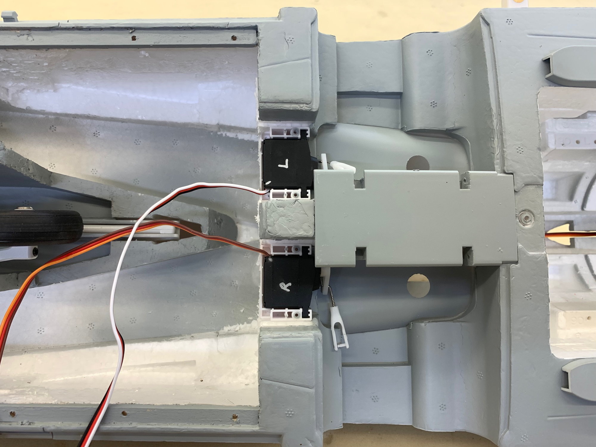
Gear door servos re-installed.
Servo covers had to be trimmed to clear the back of the main tank.
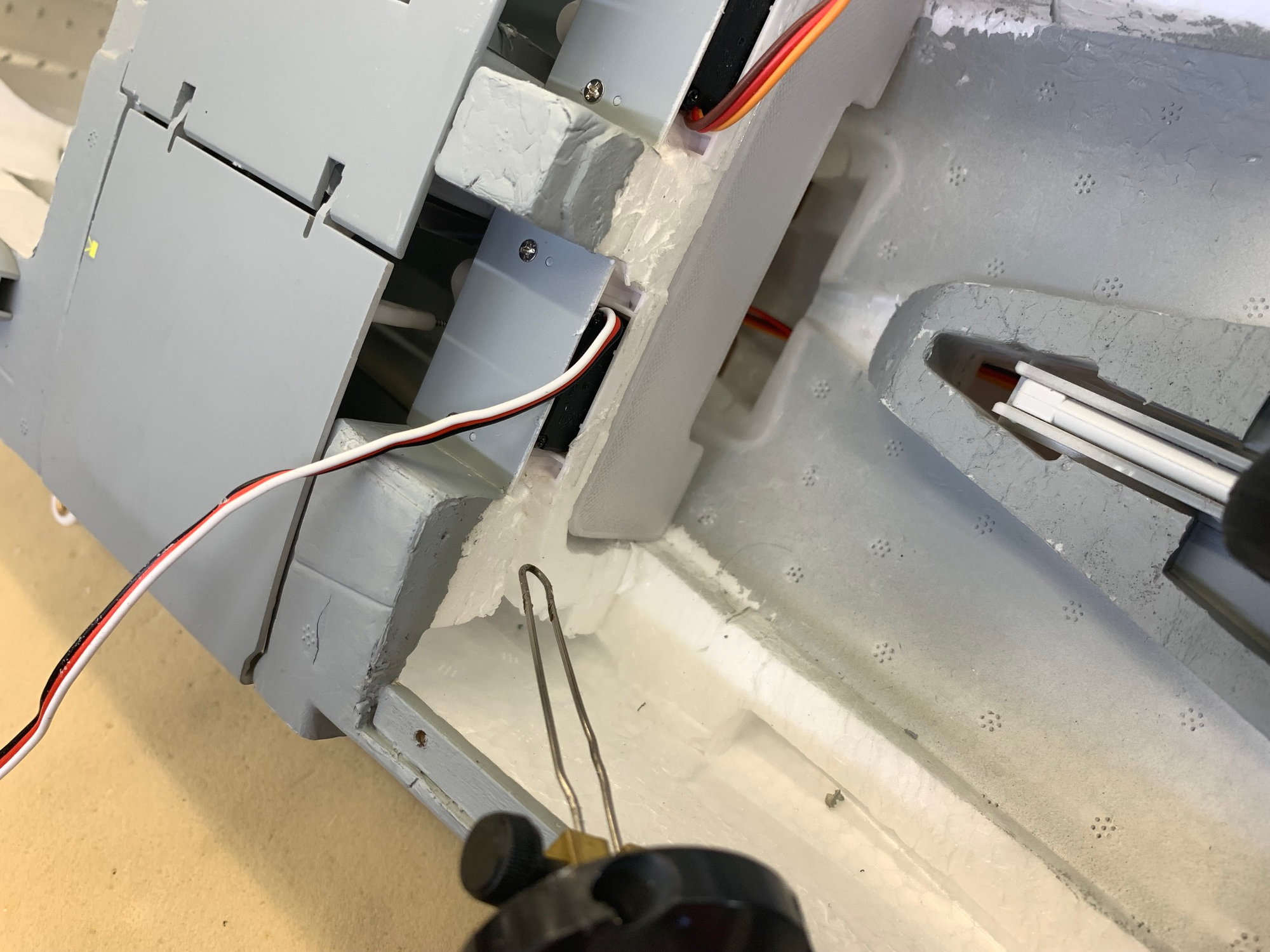
Servo covers installed and wire channel cut in foam with hot wire cutter.
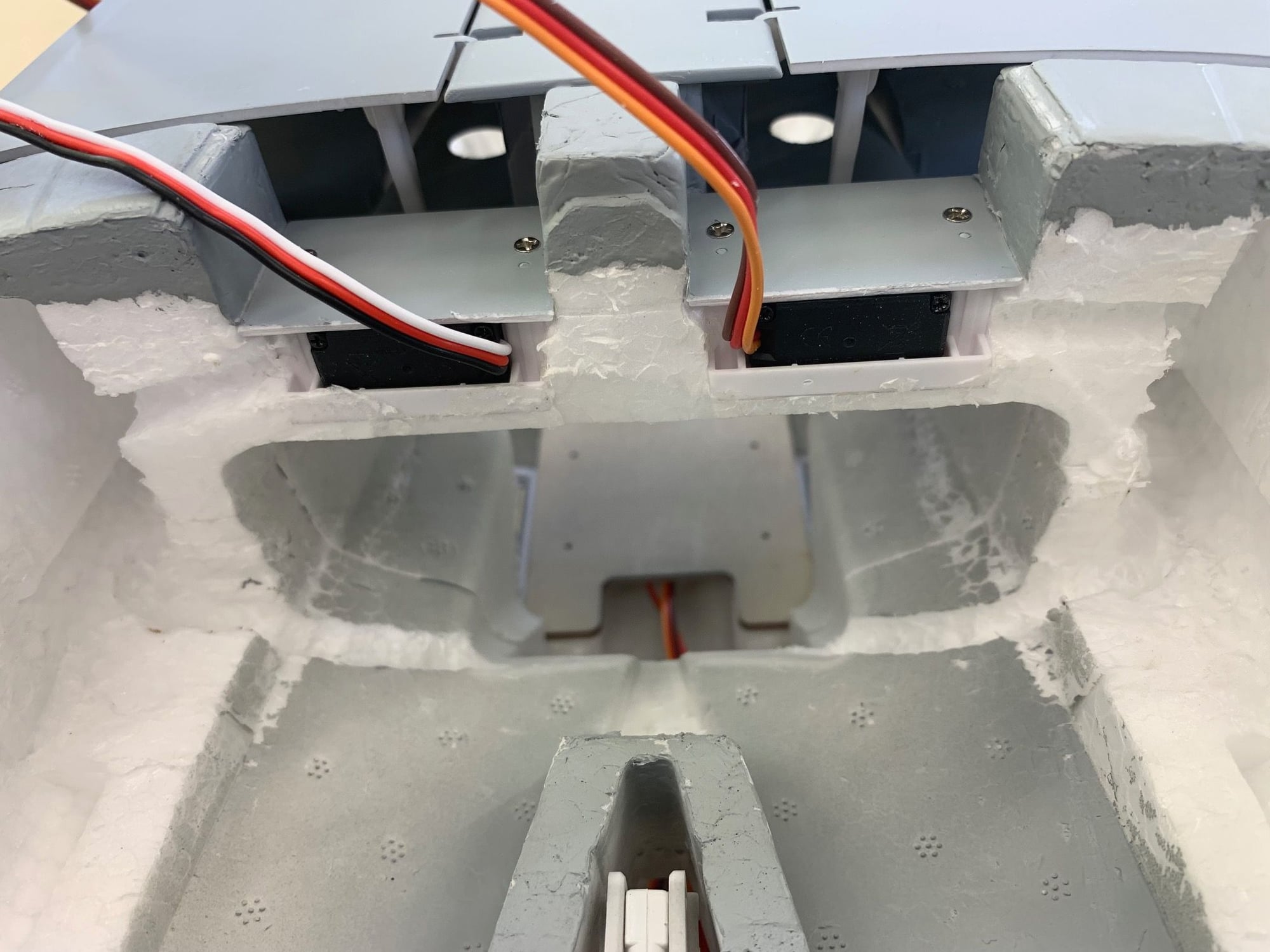
WIre channels cut on both sides.
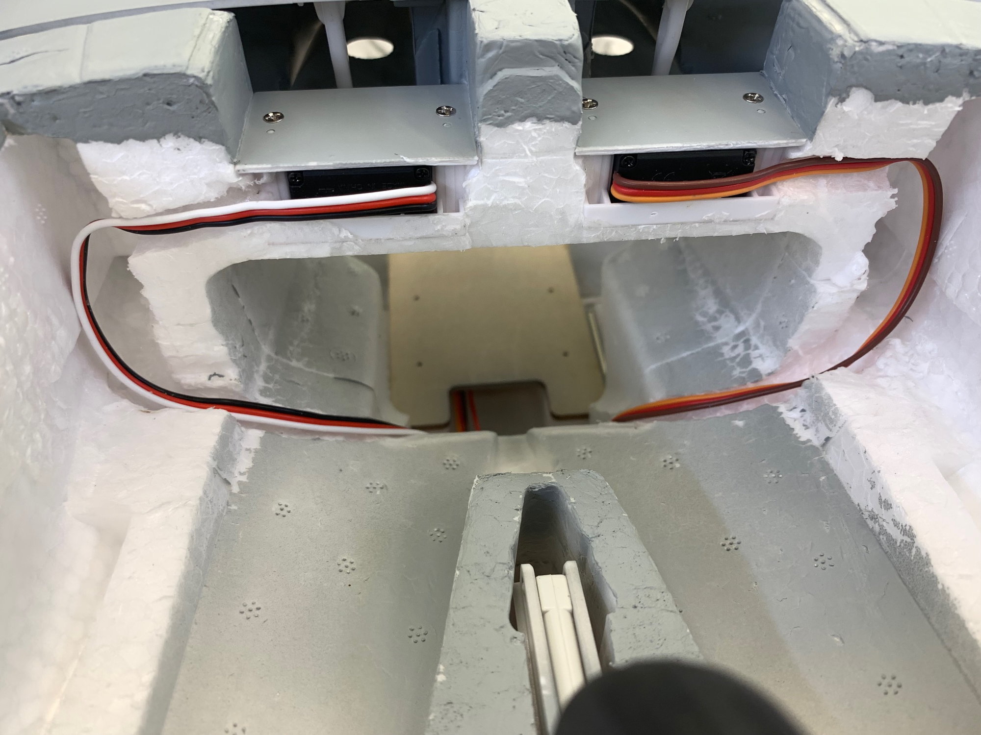
Servo wires placed in wire channels.
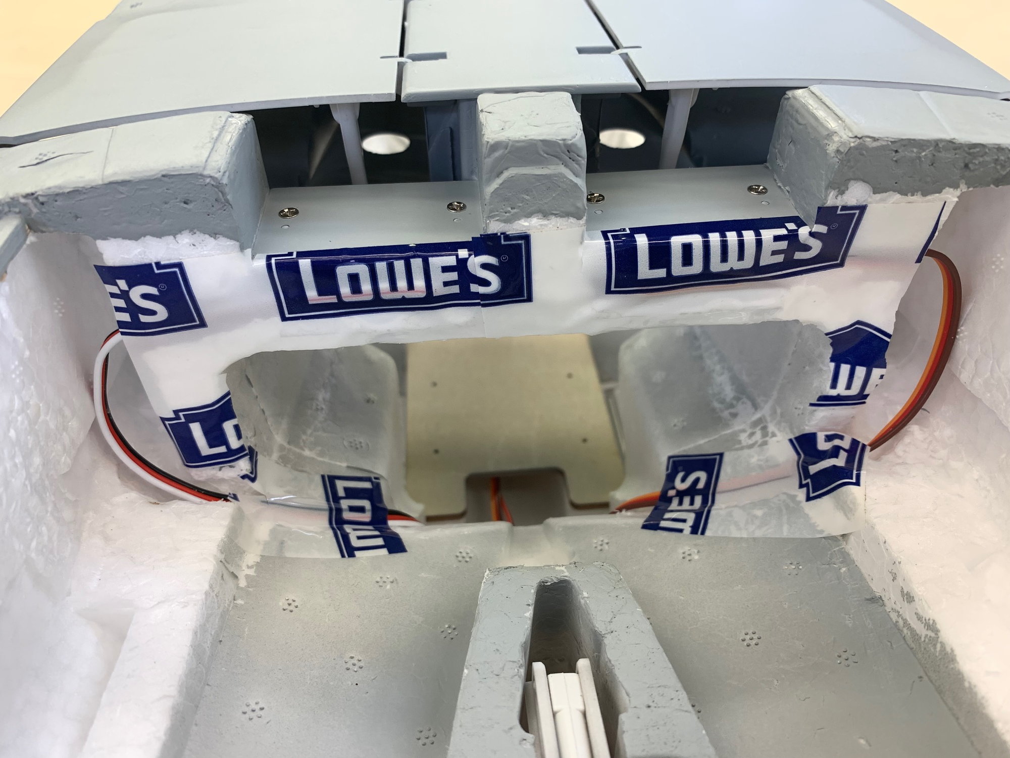
Wires taped in place with Tevyk house wrap tape from Lowes.
Fuel tank screws painted and installed.
Servo well cover trimmed to fit and glued in place with foam glue.
Gear door servos re-installed.
Servo covers had to be trimmed to clear the back of the main tank.
Servo covers installed and wire channel cut in foam with hot wire cutter.
WIre channels cut on both sides.
Servo wires placed in wire channels.
Wires taped in place with Tevyk house wrap tape from Lowes.
Fuel tank screws painted and installed.
Servo well cover trimmed to fit and glued in place with foam glue.
Last edited by Viper1GJ; 05-03-2023 at 05:08 PM.

The following users liked this post:
jcterrettaz (05-04-2023)
05-04-2023, 04:01 AM
#27

Great going!! I would strongly advice printing with Woodfill filament, it's PLA with wood powder in in. it prints a little porous like balsa wood. When you infuse it with 24h heated epoxy(thing as water almost) it sucks this up like a sponge and turns in to a composite. Very good way of making fuel tanks. PET, ABS or other plastics won't combine with epoxy, while the woodfill acts like any wood and soaks it up and bonds superb.
The following users liked this post:
Jason3 (06-06-2023)
05-04-2023, 04:50 AM
#28
Thread Starter
My Feedback: (20)
Great going!! I would strongly advice printing with Woodfill filament, it's PLA with wood powder in in. it prints a little porous like balsa wood. When you infuse it with 24h heated epoxy(thing as water almost) it sucks this up like a sponge and turns in to a composite. Very good way of making fuel tanks. PET, ABS or other plastics won't combine with epoxy, while the woodfill acts like any wood and soaks it up and bonds superb.
Thanks for following the Eurofighter conversion build. I've seen your comment on woodfill filament before. It sounds interesting. Can you give us more details on the process.
Do you have a link for buying the woodfill PLA?
What epoxy are you using?
How are you applying or infusing the epoxy?
How do you heat it during cure?
Any photos of the process or finished tank?
Thanks,
Gary

The following users liked this post:
Viper1GJ (05-04-2023)
05-04-2023, 04:44 PM
#30
Thread Starter
My Feedback: (20)
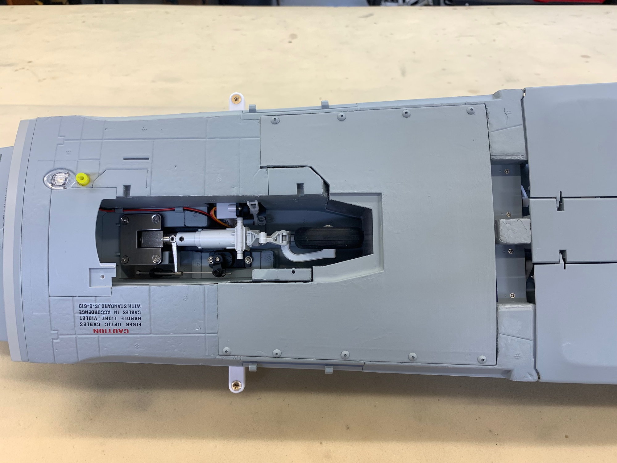
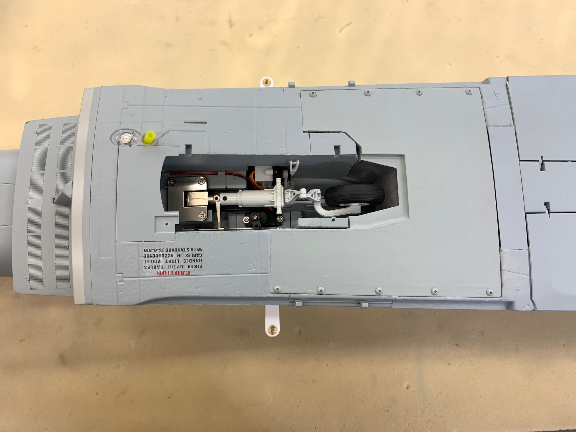
Installed nose door and pulled all wires
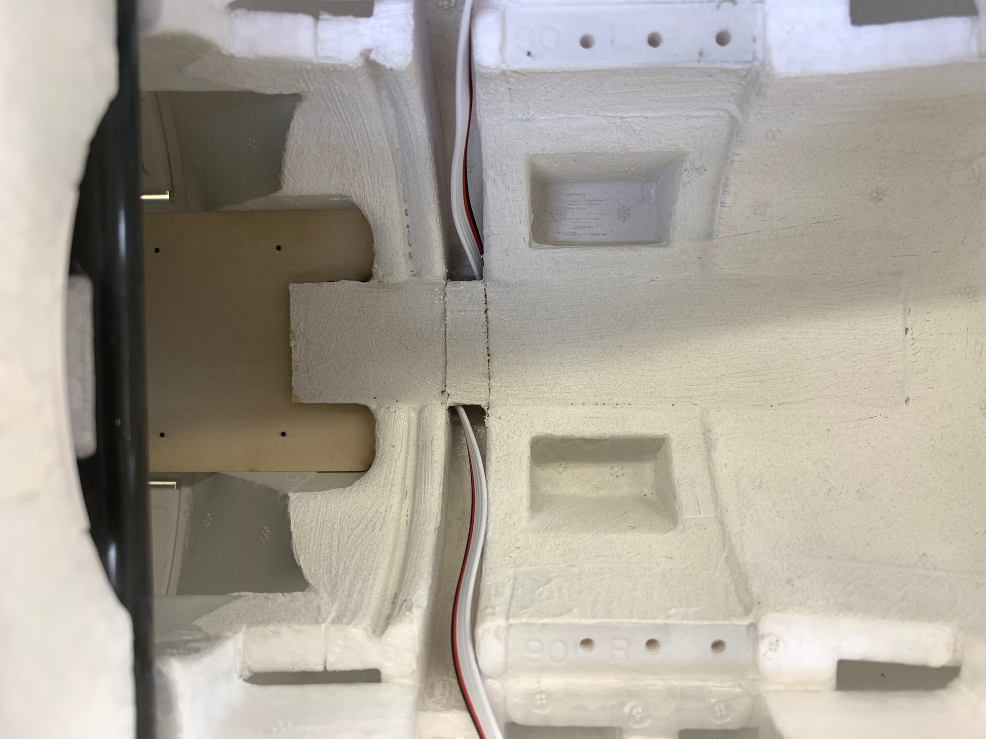
Keith did a great job with the CAD fit of the nose door into the bottom of the main tank. I'm very happy with the fit of both tanks.
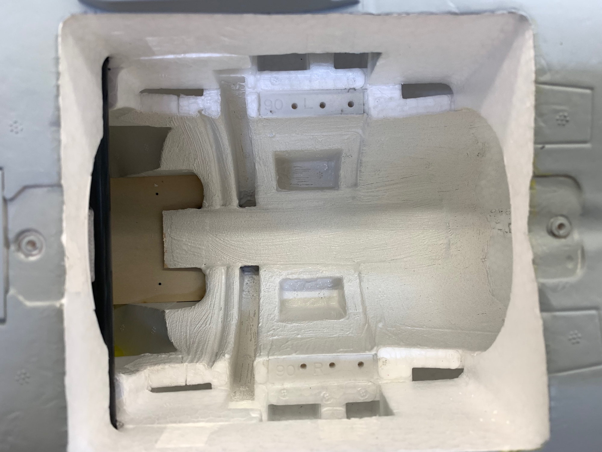
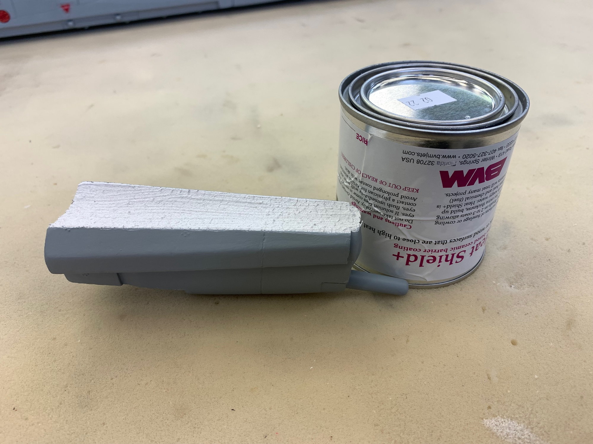
I glued a balsa strip over the top of the turbine bay to shield the rudder servo wire and brushed BVM Heat Shield on top of turbine bay.
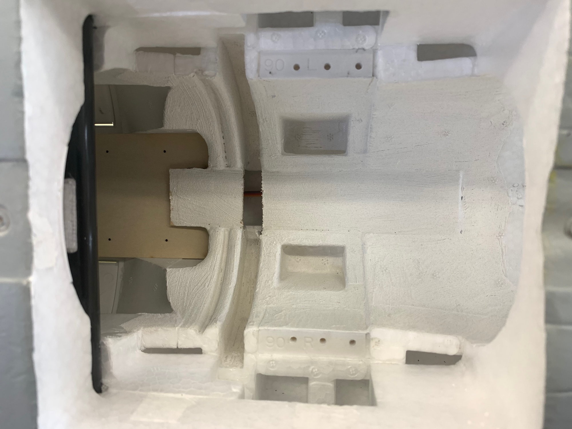
OOPS! I forgot to install the ribbon cables to the wings before installing the heat shield over the turbine bay. I had to cut out the middle of the balsa strip to get the ribbon cable plugs in the hole.
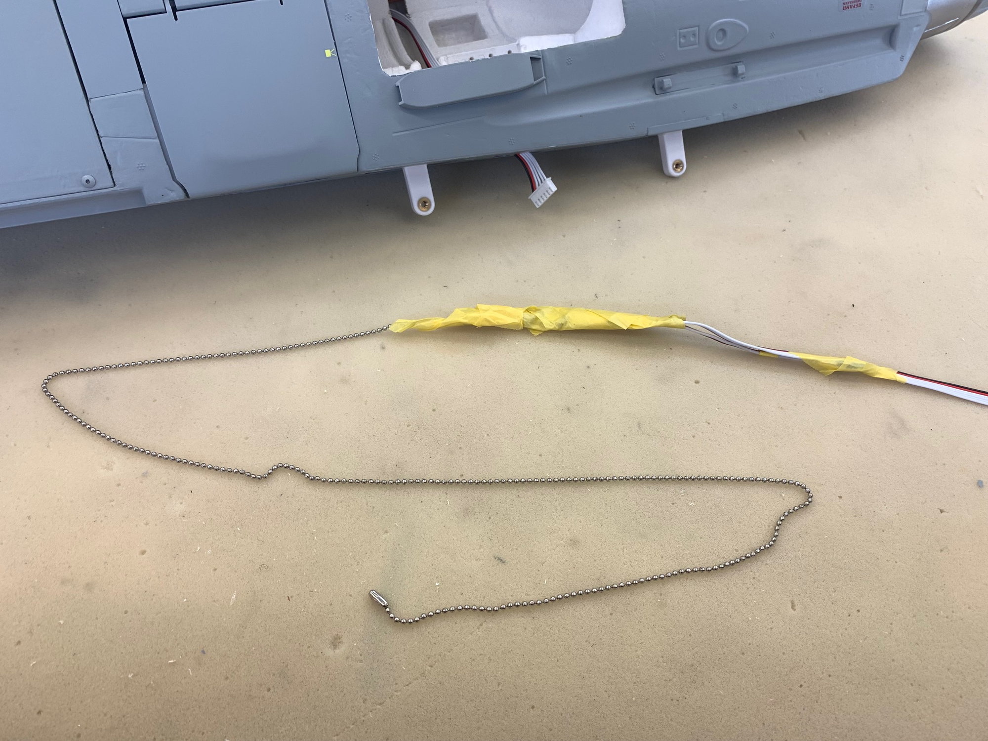
I've use the ceiling fan pull chain method to fish wires through wire channels for many years. So far it has never failed to snake through the channel even when curved inside a foam wing. It worked well here. I wrapped the chain around the ribbon cables and ECU cable, taped it on, dropped it into the channel, and pulled the wires through.
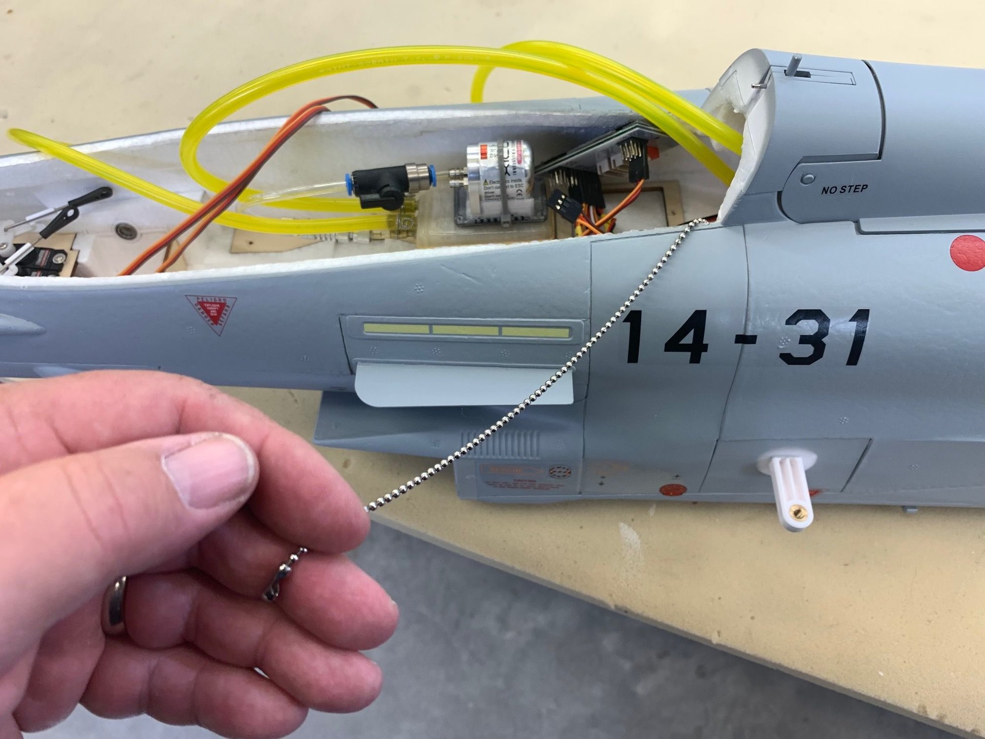
Pull here!
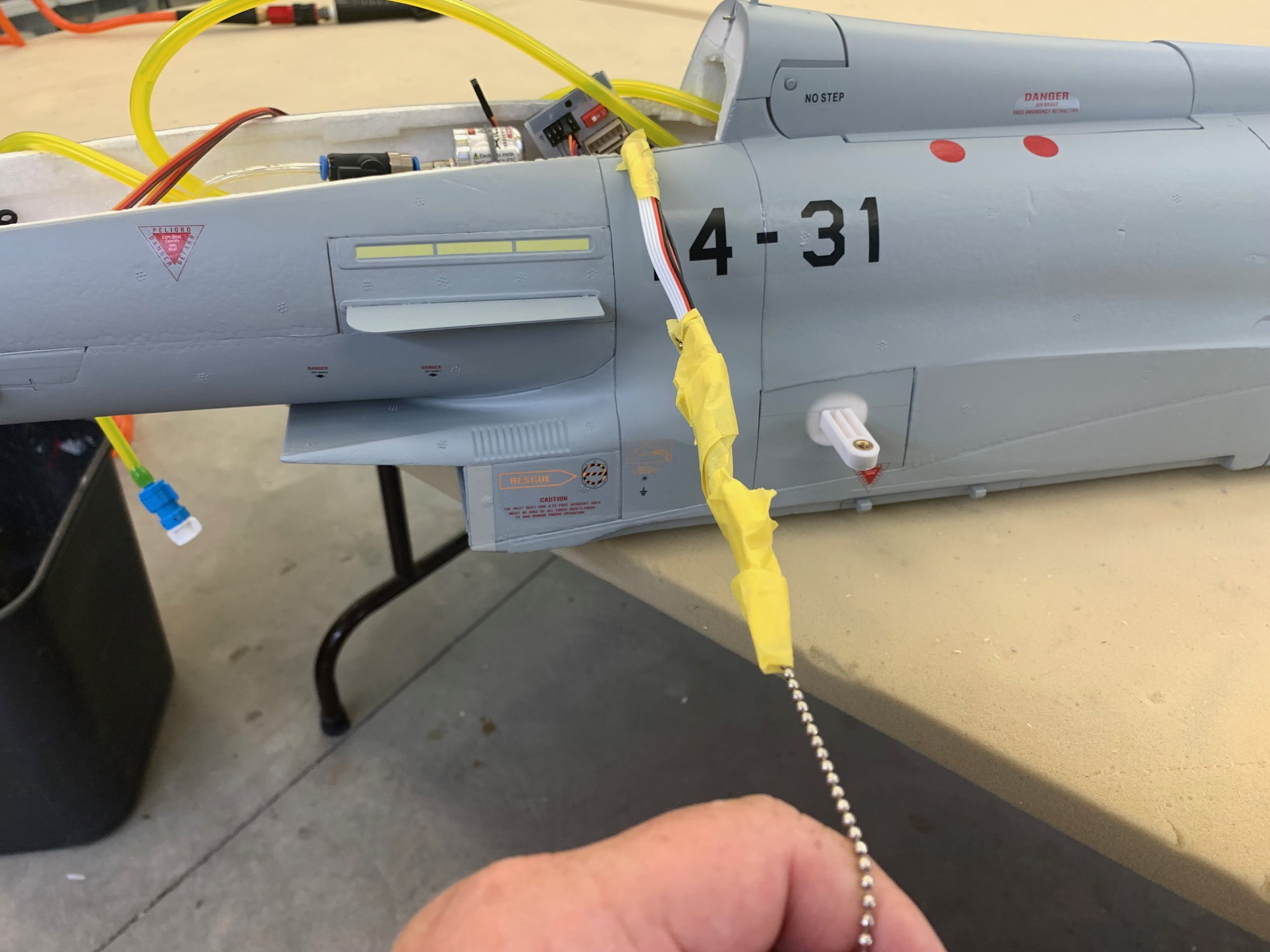
Remove tape and it's done.
Ribbon cables installed and balsa heat shield repaired. I recoated with heat shield paint later so the cuts are hardly visible.
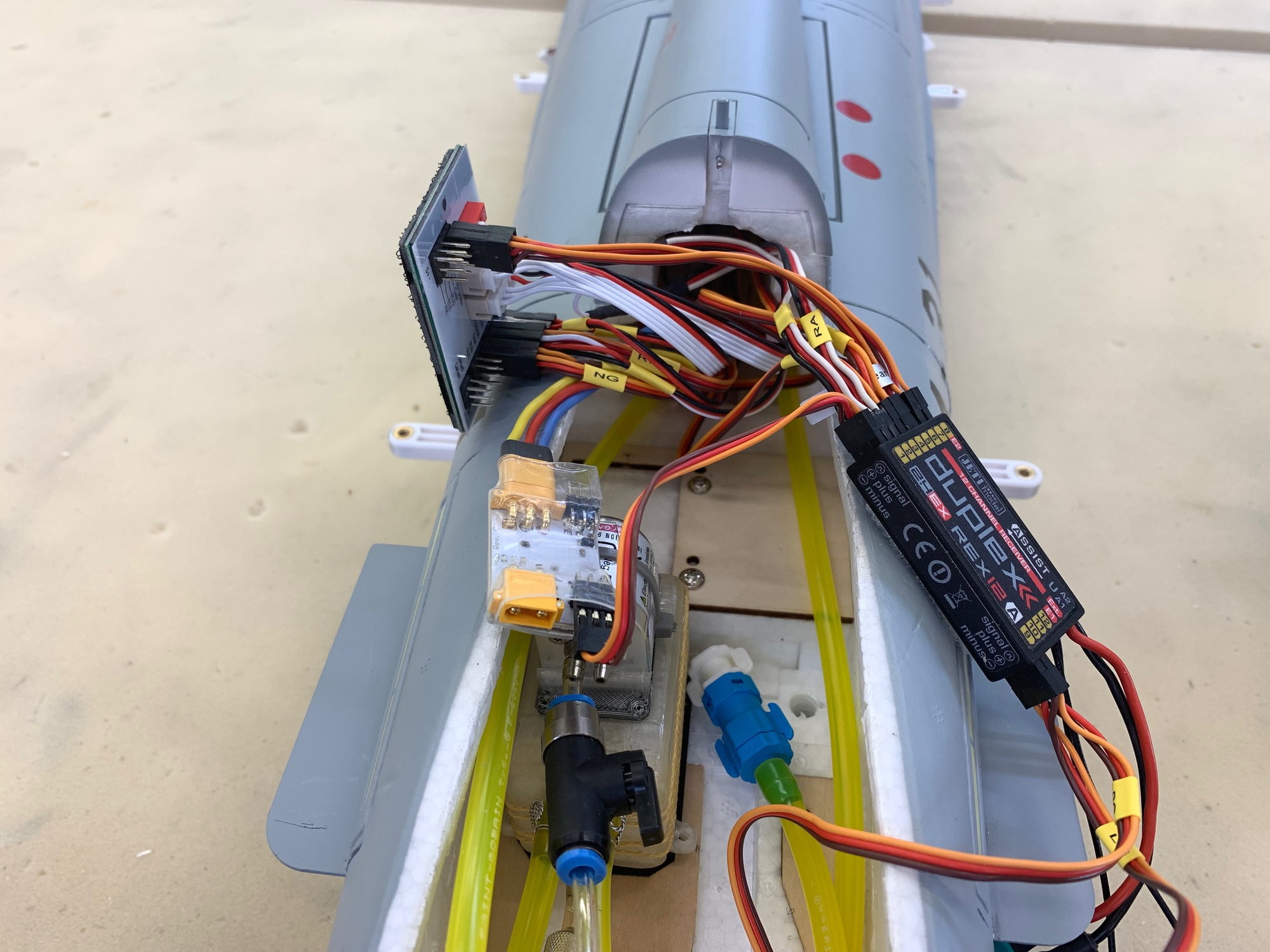
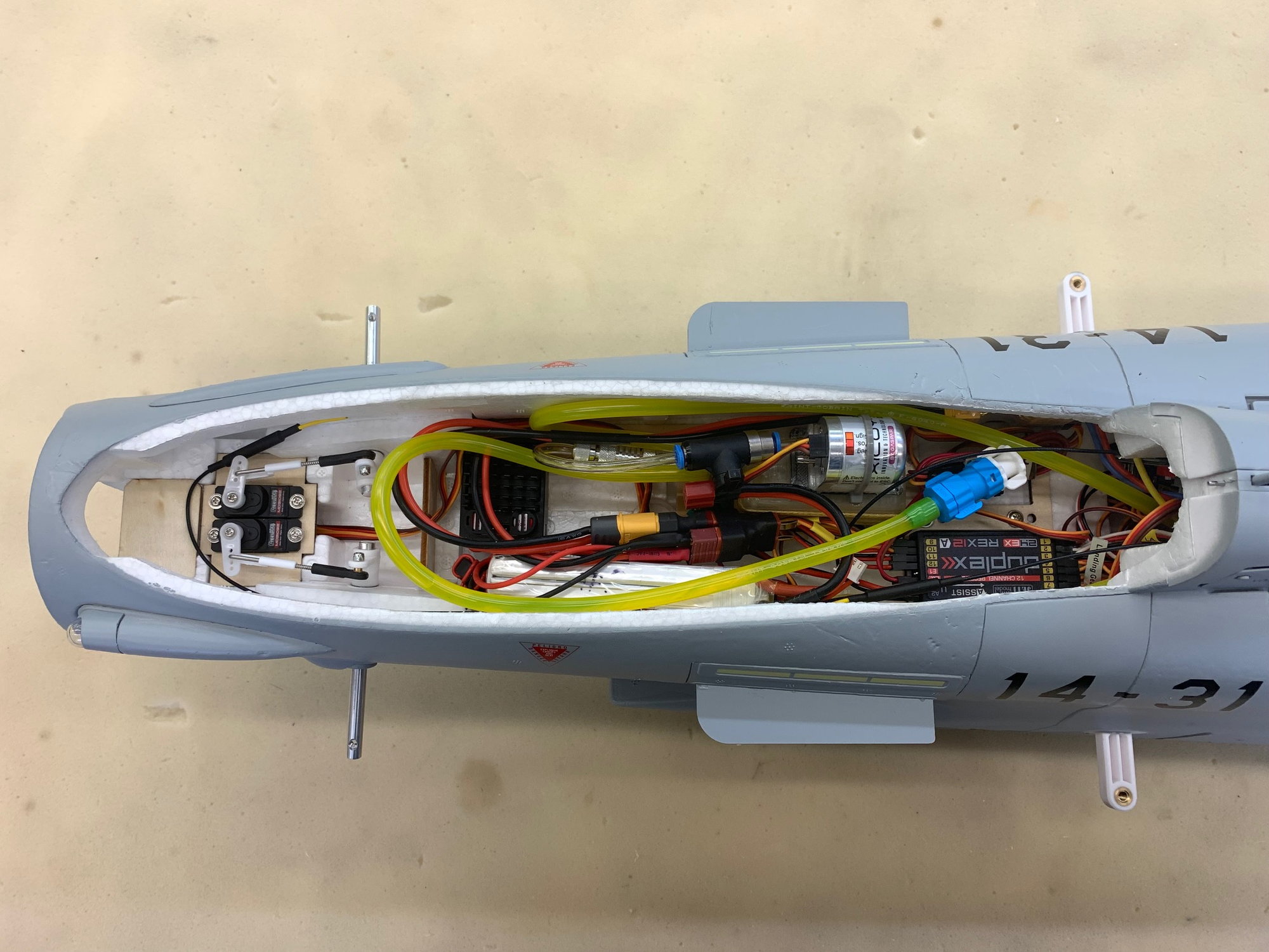
Started hooking up the Freewing board, Jeti receiver, and XIcoy turbine module. The Freewing board will run the lights and gear system. All other controls are from the Jeti REX12A receiver. The wire labels applied earlier in the build were really helpful. Looks like an explosion in a hook up wire factory here!
Keith did a great job with the CAD fit of the nose door into the bottom of the main tank. I'm very happy with the fit of both tanks.
I glued a balsa strip over the top of the turbine bay to shield the rudder servo wire and brushed BVM Heat Shield on top of turbine bay.
OOPS! I forgot to install the ribbon cables to the wings before installing the heat shield over the turbine bay. I had to cut out the middle of the balsa strip to get the ribbon cable plugs in the hole.
I've use the ceiling fan pull chain method to fish wires through wire channels for many years. So far it has never failed to snake through the channel even when curved inside a foam wing. It worked well here. I wrapped the chain around the ribbon cables and ECU cable, taped it on, dropped it into the channel, and pulled the wires through.
Pull here!
Remove tape and it's done.
Ribbon cables installed and balsa heat shield repaired. I recoated with heat shield paint later so the cuts are hardly visible.
Started hooking up the Freewing board, Jeti receiver, and XIcoy turbine module. The Freewing board will run the lights and gear system. All other controls are from the Jeti REX12A receiver. The wire labels applied earlier in the build were really helpful. Looks like an explosion in a hook up wire factory here!
Last edited by Viper1GJ; 05-04-2023 at 04:47 PM.
The following users liked this post:
Afterburners (05-04-2023)

 05-05-2023, 05:00 PM
#33
Thread Starter
My Feedback: (20)
Gary
05-05-2023, 05:16 PM
#34
Thread Starter
My Feedback: (20)
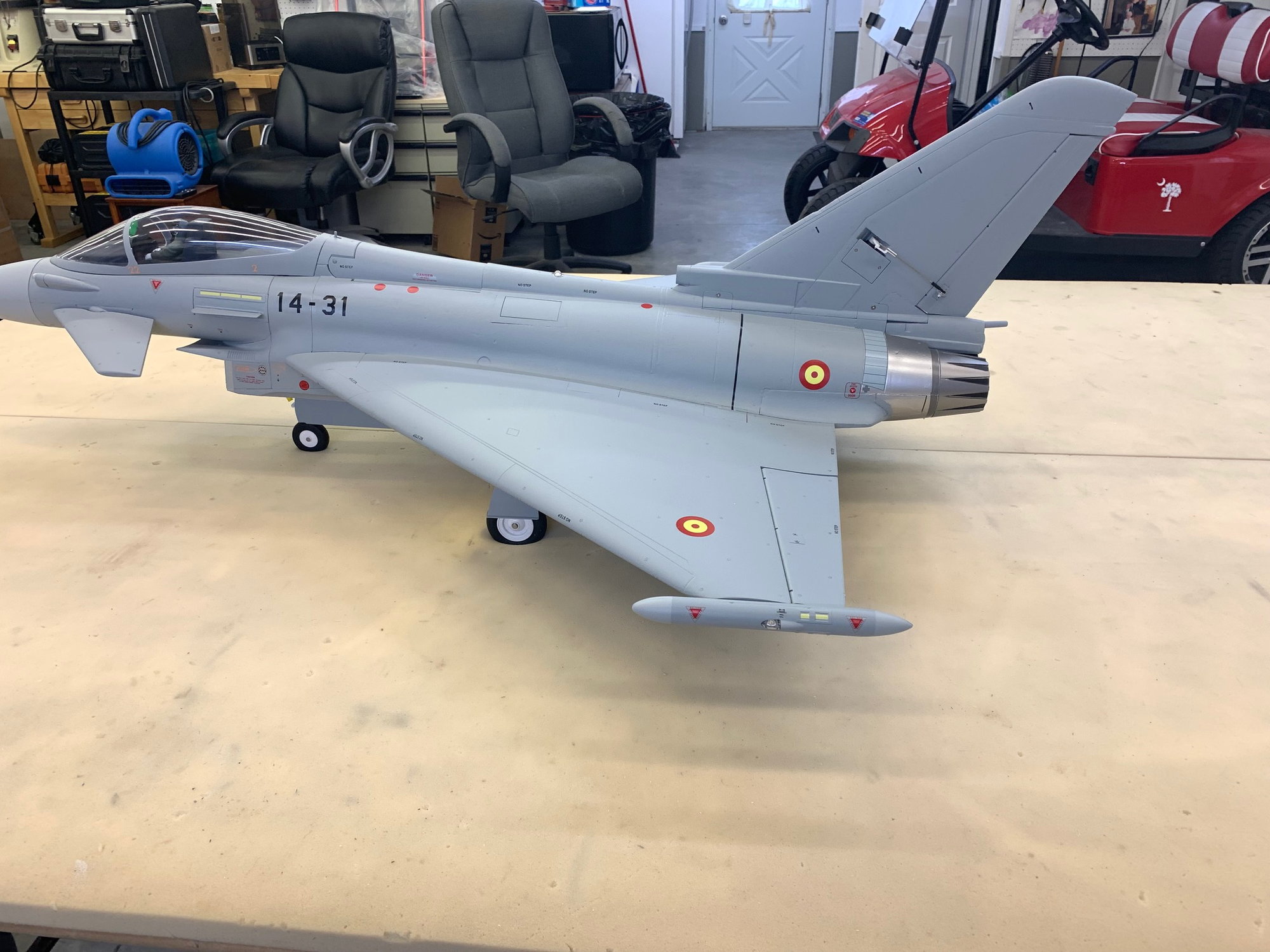
Final Assembly
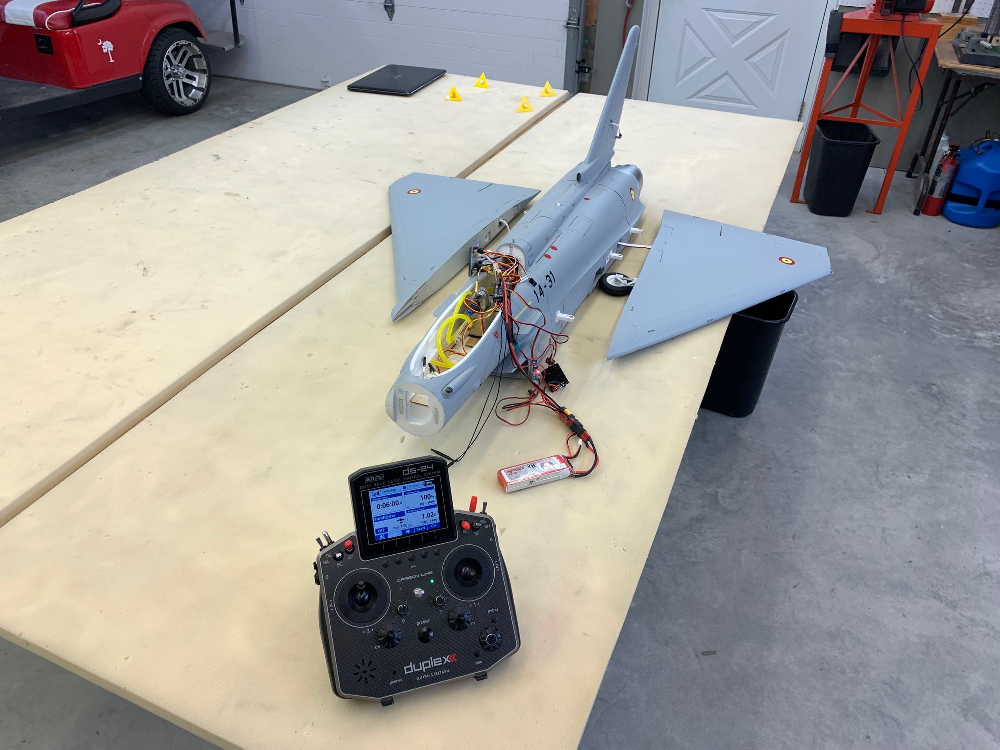
I hooked up everything up for an initial ops check. I was shocked to find that everything was working as planned including turbine telemetry! That rarely happens for me on a new jet.
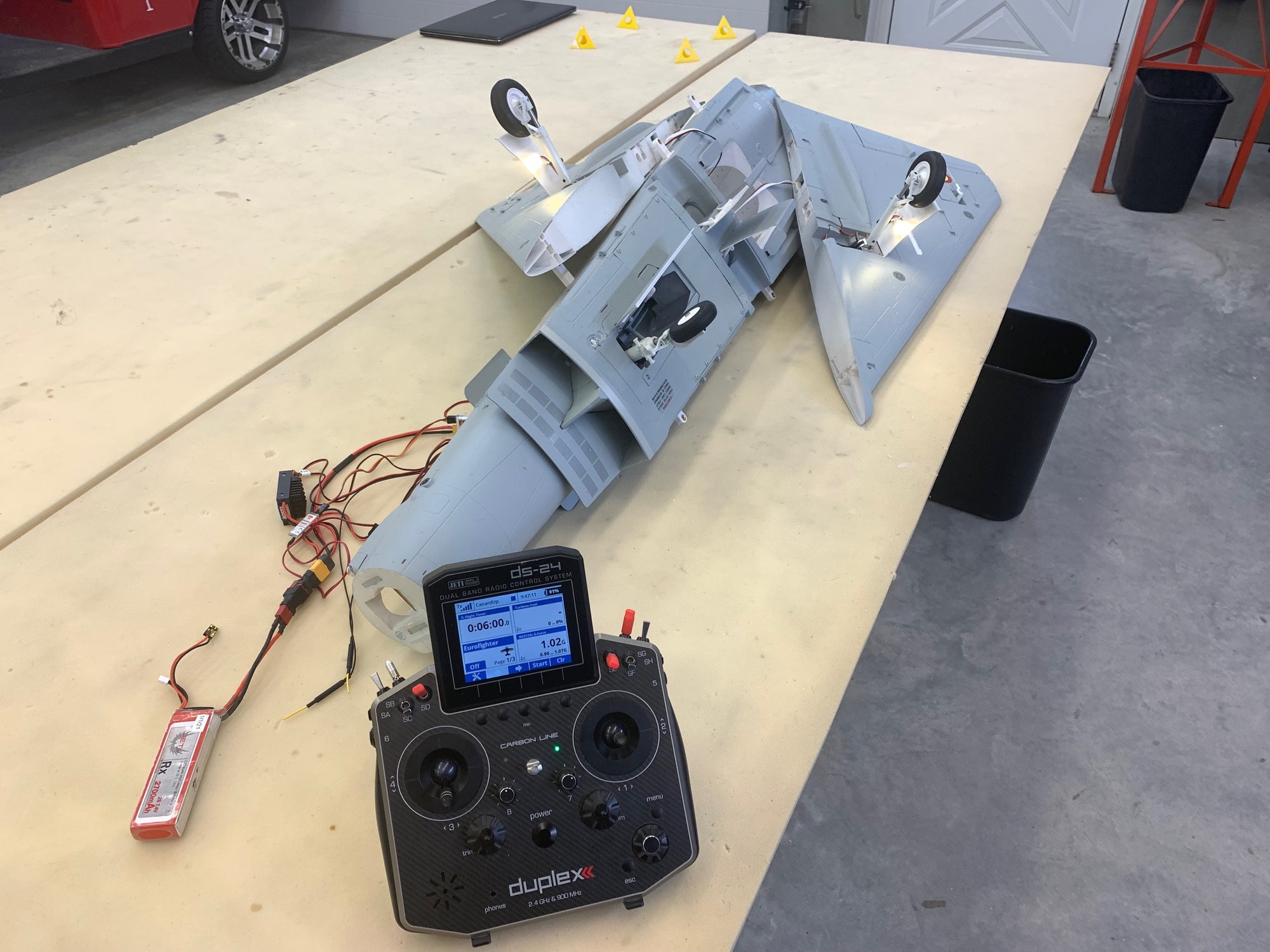
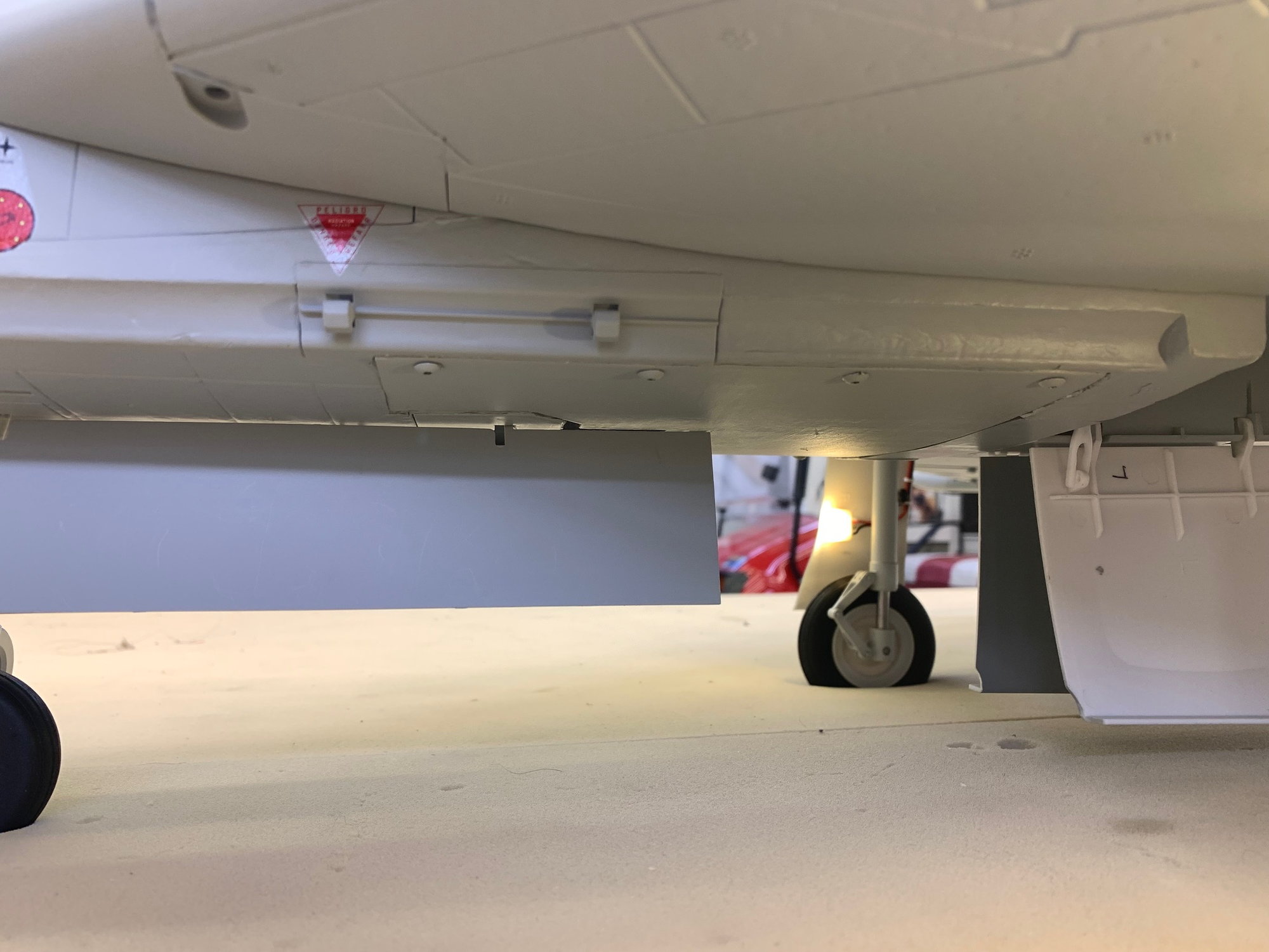
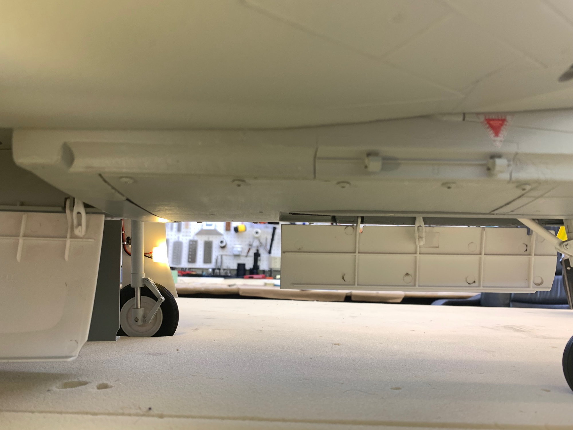
I flipped it all over to check the gear system. All the gear and doors worked correctly.
No way to hide the rats nest. For now the battery is under the cockpit but I expect it will have to move to the nose for proper balance.
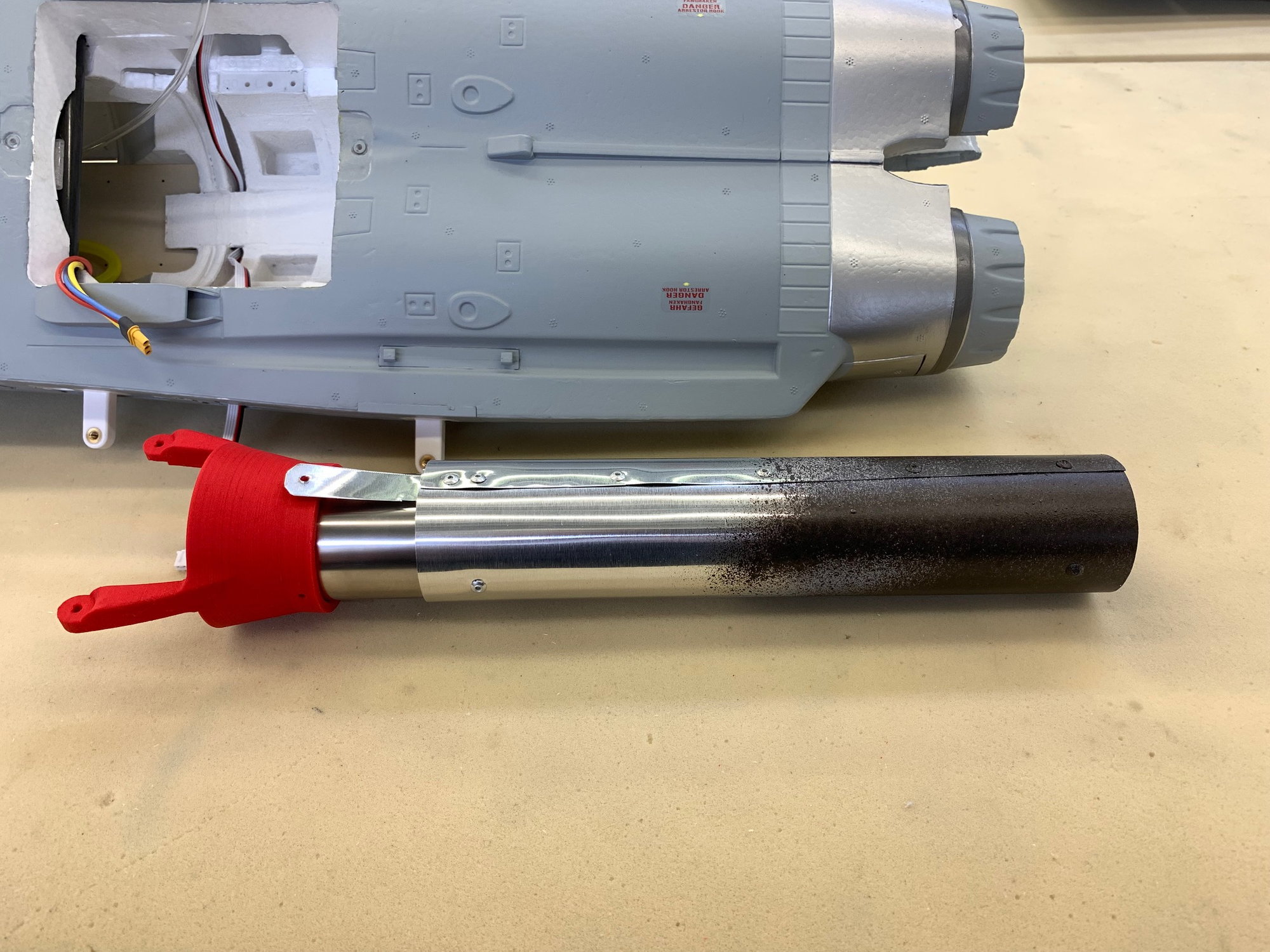
I was trying to give the aft end of the pipe a darker color to blend in with the model nozzles. I sprayed primer on the back end and then intended to give the back end a light dusting of the "oil rubbed bronze" color. However, the spray can started spitting large drops so I had to go with a spotted coat darker than planned.
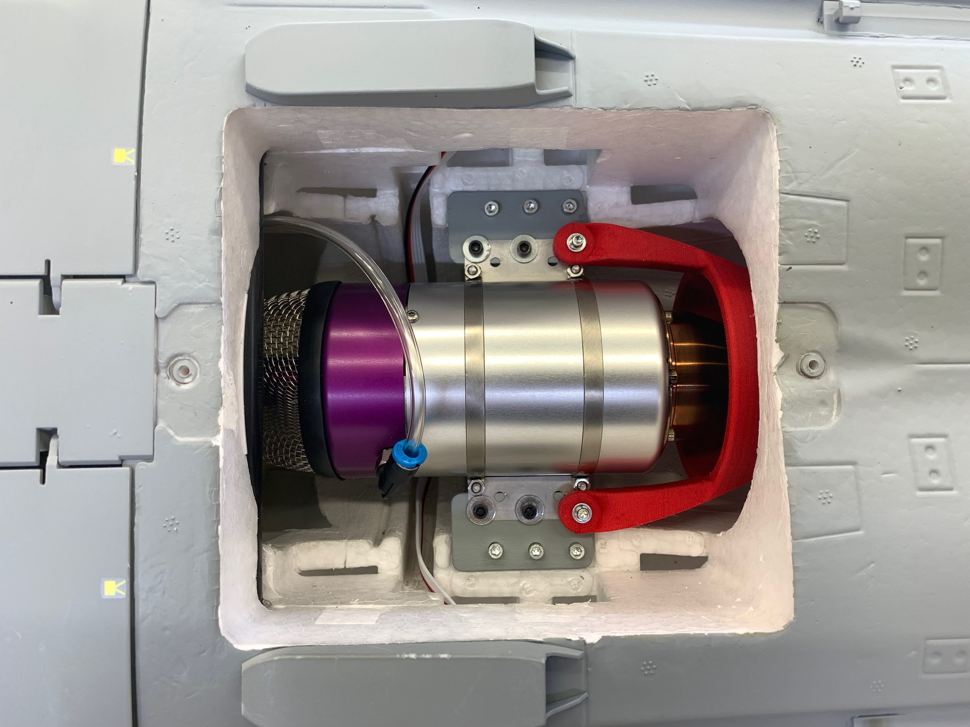
Turbine and pipe installed with electrical and fuel connections. I still have to heat shield the ribbon cables to the wings.
BVM Heat Shield painted on bottom of the foam plug that lives under the rudder.
I hooked up everything up for an initial ops check. I was shocked to find that everything was working as planned including turbine telemetry! That rarely happens for me on a new jet.
I flipped it all over to check the gear system. All the gear and doors worked correctly.
No way to hide the rats nest. For now the battery is under the cockpit but I expect it will have to move to the nose for proper balance.
I was trying to give the aft end of the pipe a darker color to blend in with the model nozzles. I sprayed primer on the back end and then intended to give the back end a light dusting of the "oil rubbed bronze" color. However, the spray can started spitting large drops so I had to go with a spotted coat darker than planned.
Turbine and pipe installed with electrical and fuel connections. I still have to heat shield the ribbon cables to the wings.
BVM Heat Shield painted on bottom of the foam plug that lives under the rudder.
05-05-2023, 05:48 PM
#35
Thread Starter
My Feedback: (20)
It's Alive!

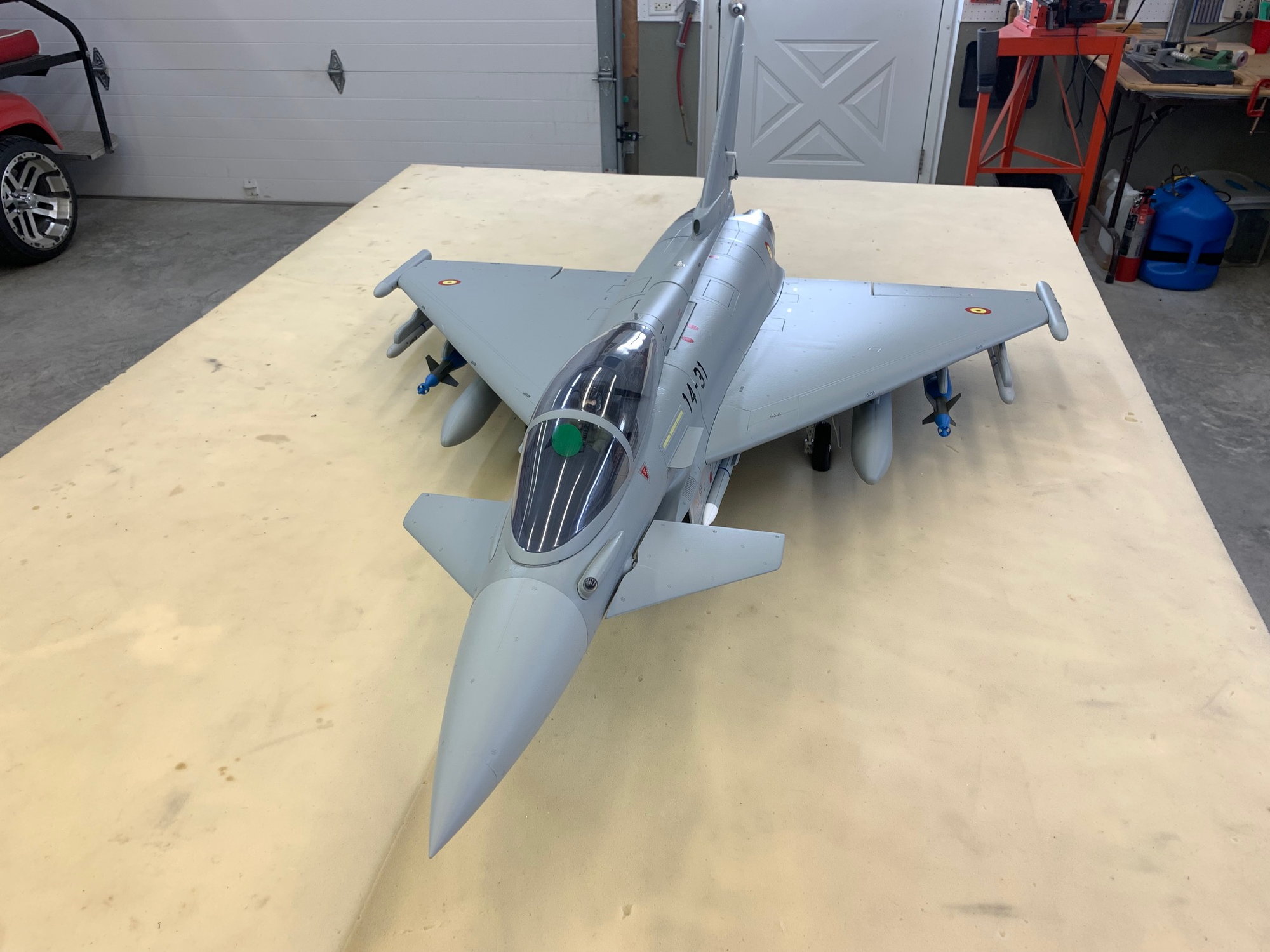
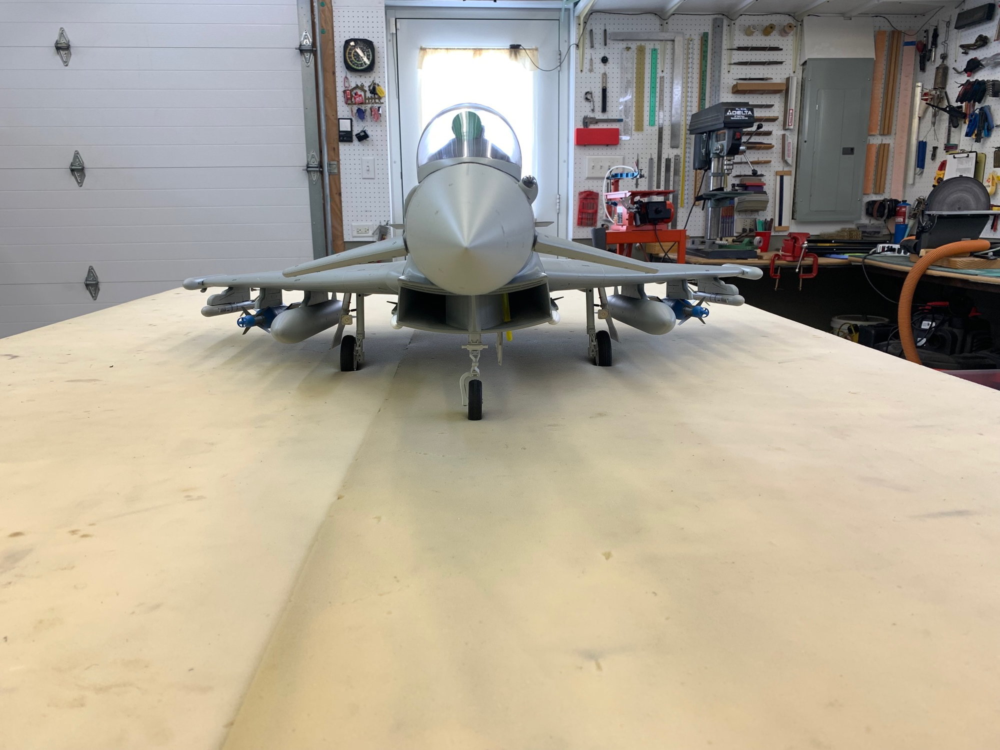
Canards, wings, vertical fin, and nozzles attached. All lights working and surfaces moving in correct directions.
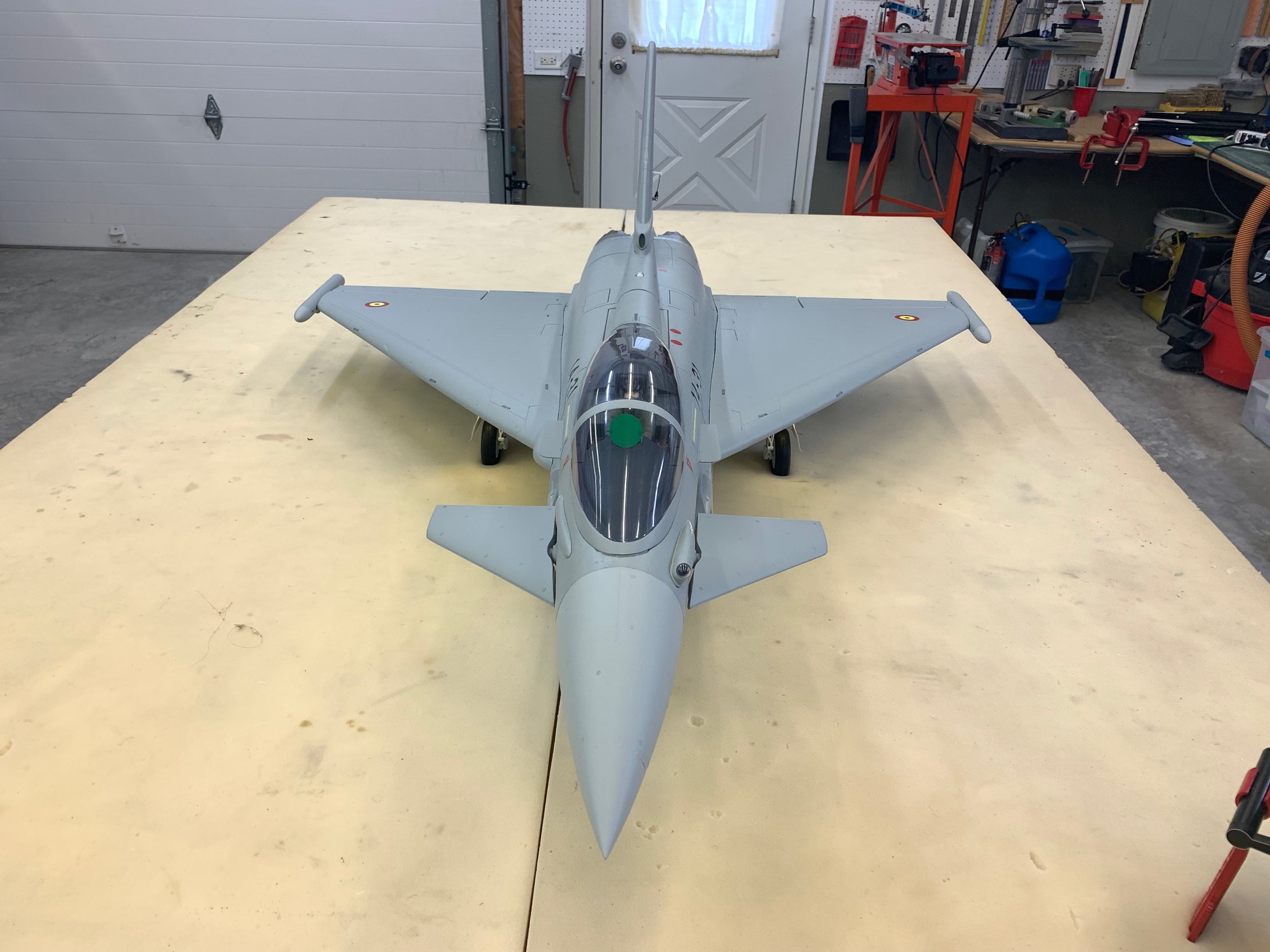
Canards have to be adjusted to neutral. They are programed to work in several modes. Off in a fixed neutral position, 3 positions operated like flaps with trailing edge down, operating in pitch only, and operating in pitch and roll.
Plenty of lights blinking
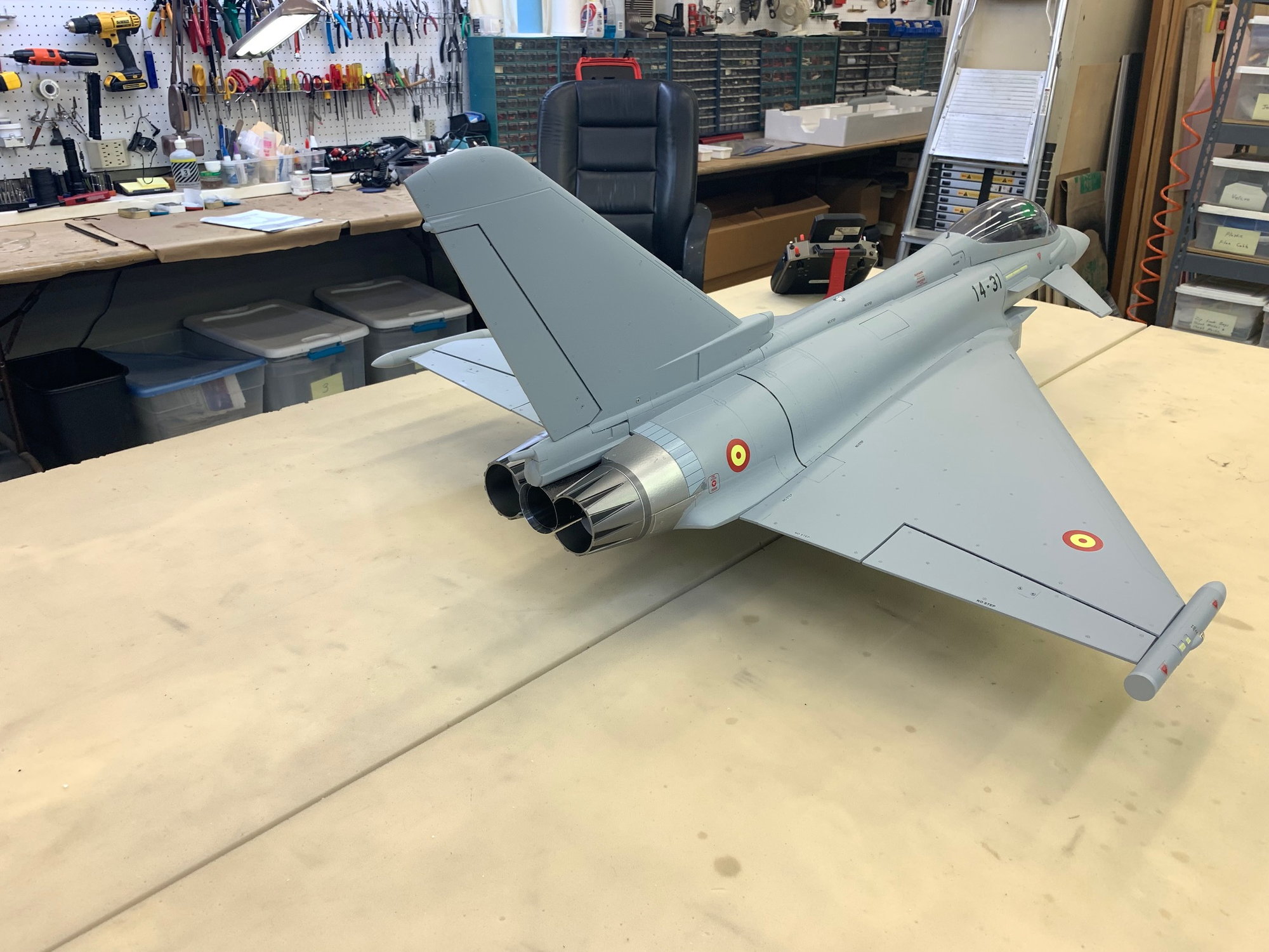
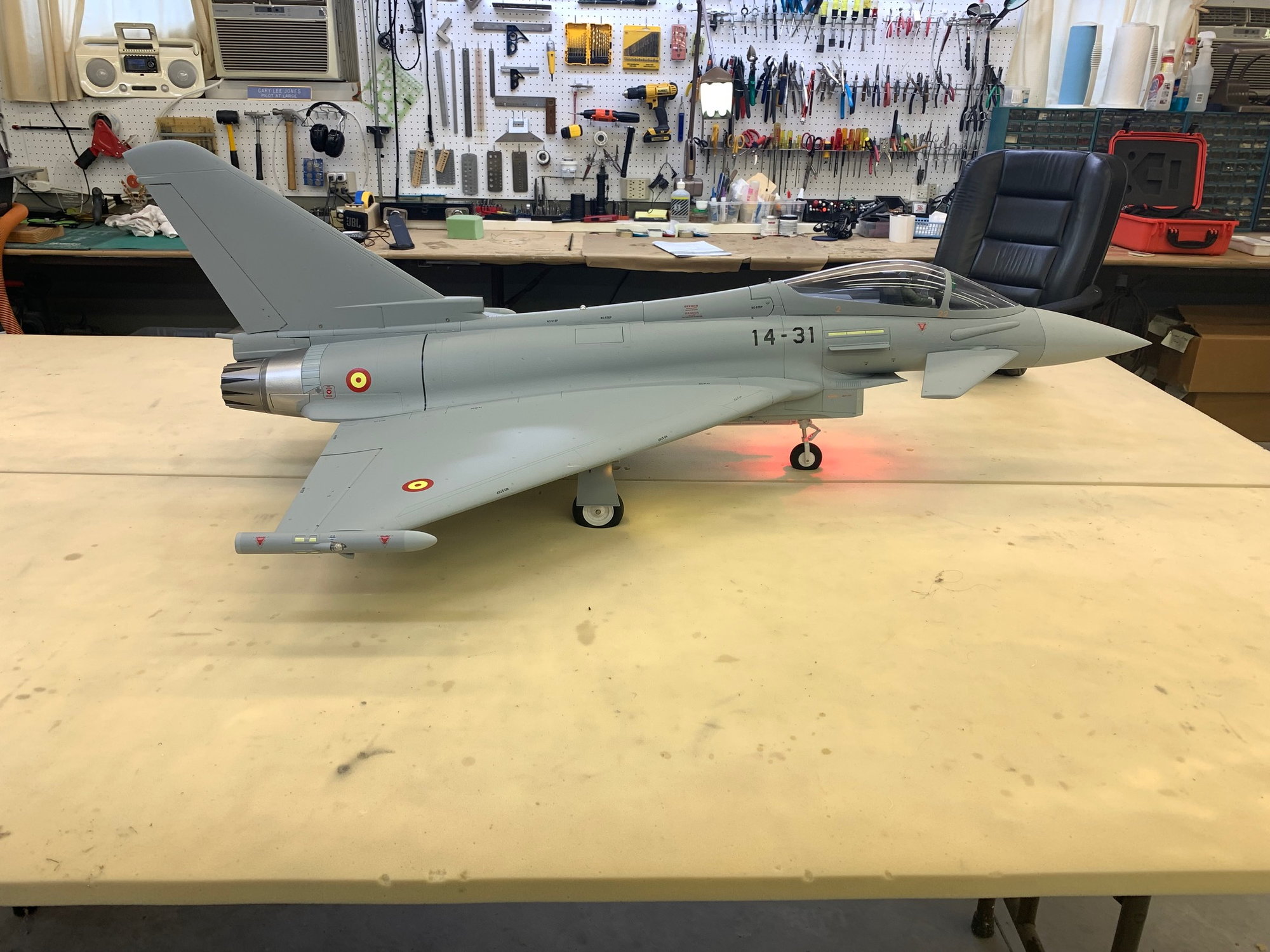
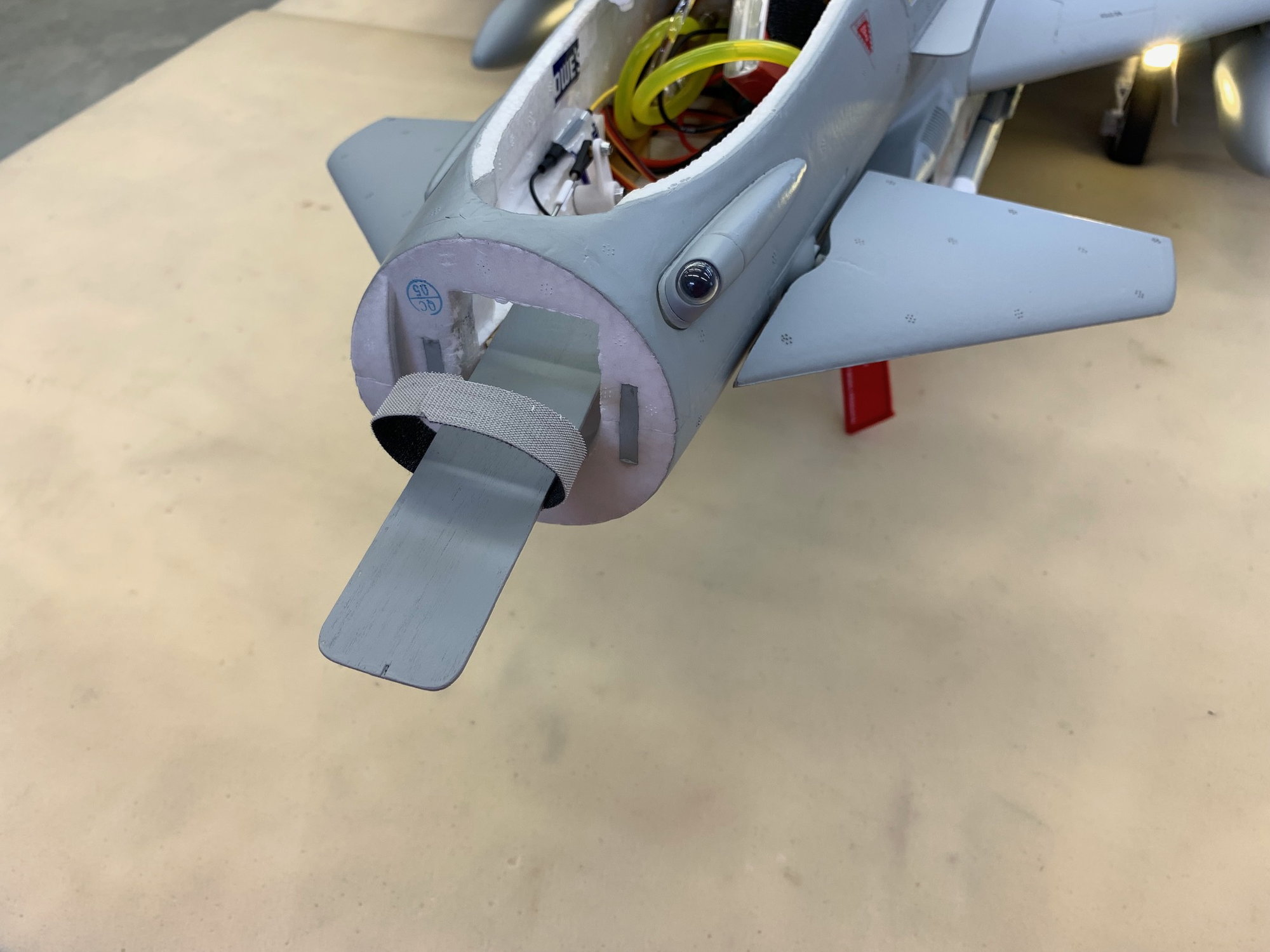
The pipe painting plan turned out ok. The pipe seems to blend in ok.
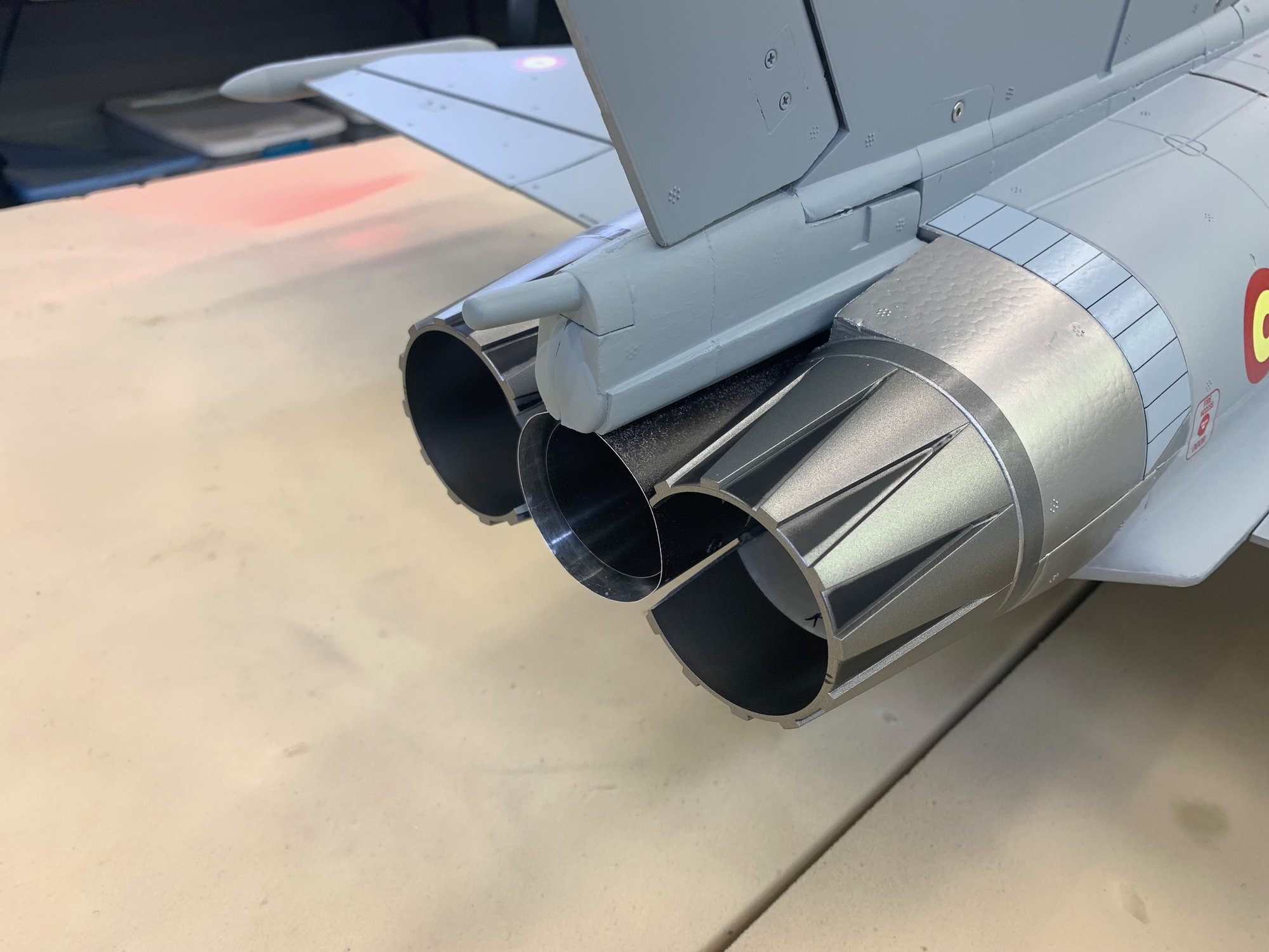
Back end looks ok.
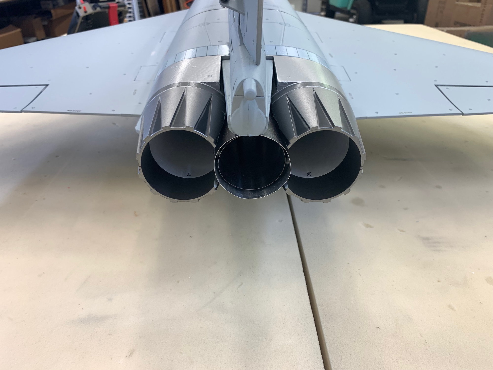
Probably need to paint the white foam inside the nozzles with the dark oil rubbed bronze color to simulate the inside of the burner cans.
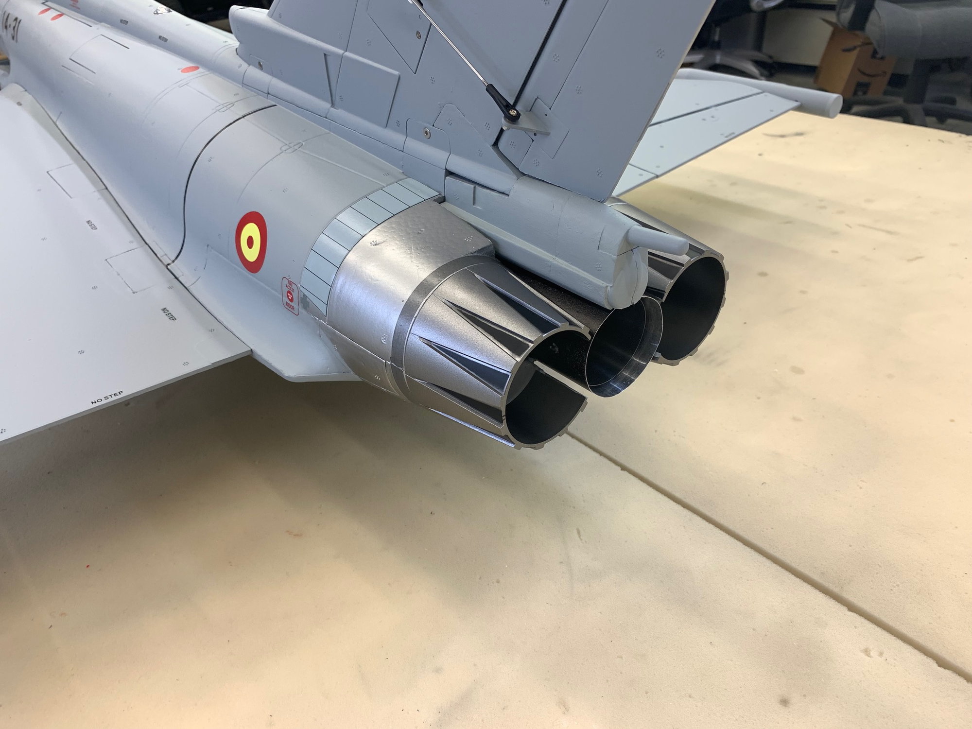
The foam plug under the rudder is a simulated ECM pod and is just stuck in place for the photo. It does not fit over the pipe correctly even after the foam cutting so I will have to sand off the BVM heat shield and shape it correctly before gluing it in.
I did a couple of finger tip CG checks and as expected it is tail heavy. I will have to move the battery to the nose cone and possibly add some additional weights.
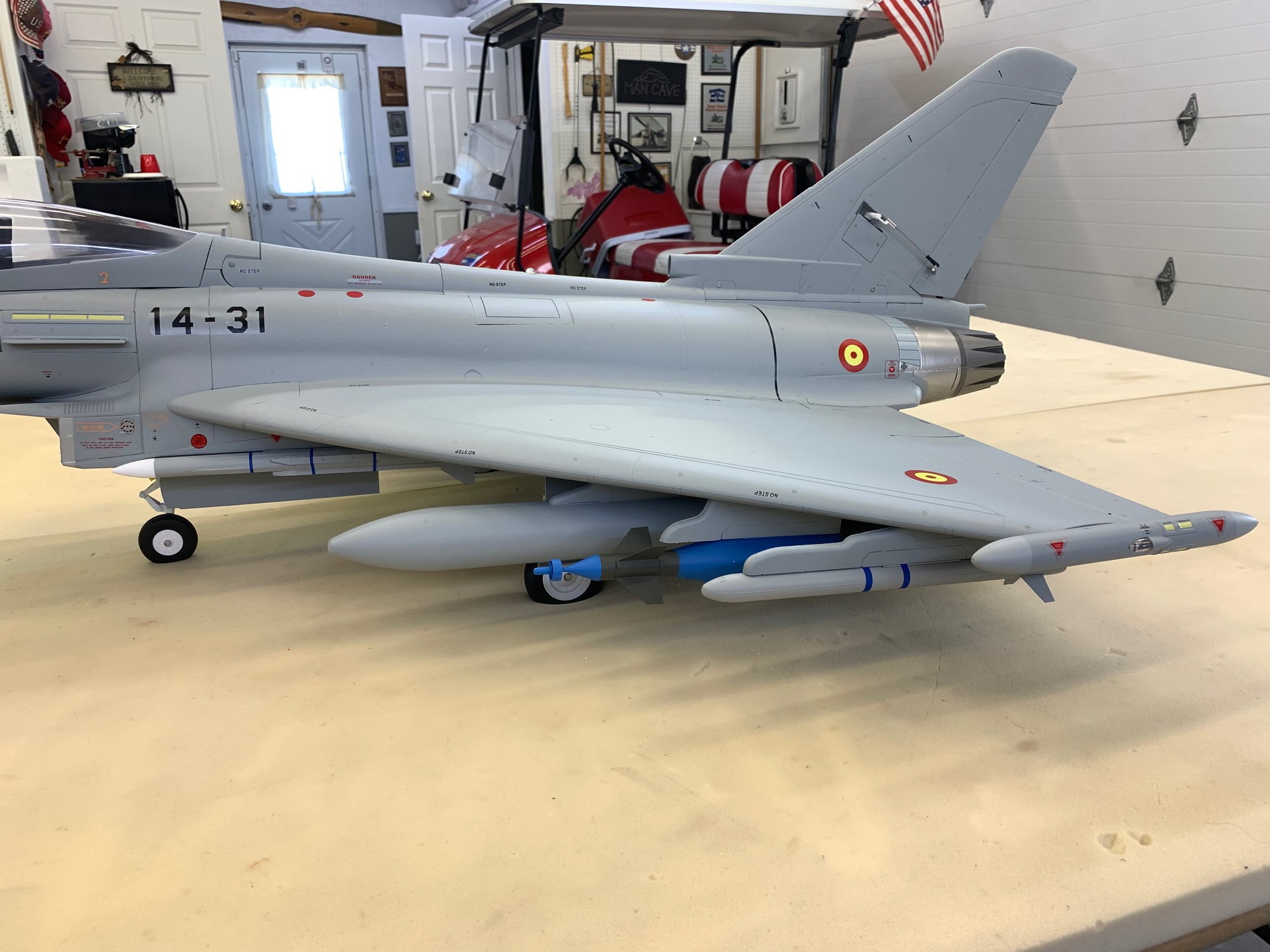
View of the fuel tank from left side.
Fuel tank from right side. I think it came out pretty good.
CG is the next step along with some final finish items, and then fuel system testing, turbine starts, and test runs. I'm out of shop time for a few days for other "honey do" projects. Back when able.
Canards, wings, vertical fin, and nozzles attached. All lights working and surfaces moving in correct directions.
Canards have to be adjusted to neutral. They are programed to work in several modes. Off in a fixed neutral position, 3 positions operated like flaps with trailing edge down, operating in pitch only, and operating in pitch and roll.
Plenty of lights blinking
The pipe painting plan turned out ok. The pipe seems to blend in ok.
Back end looks ok.
Probably need to paint the white foam inside the nozzles with the dark oil rubbed bronze color to simulate the inside of the burner cans.
The foam plug under the rudder is a simulated ECM pod and is just stuck in place for the photo. It does not fit over the pipe correctly even after the foam cutting so I will have to sand off the BVM heat shield and shape it correctly before gluing it in.
I did a couple of finger tip CG checks and as expected it is tail heavy. I will have to move the battery to the nose cone and possibly add some additional weights.
View of the fuel tank from left side.
Fuel tank from right side. I think it came out pretty good.
CG is the next step along with some final finish items, and then fuel system testing, turbine starts, and test runs. I'm out of shop time for a few days for other "honey do" projects. Back when able.
Last edited by Viper1GJ; 05-05-2023 at 05:52 PM.
05-07-2023, 02:56 AM
#36
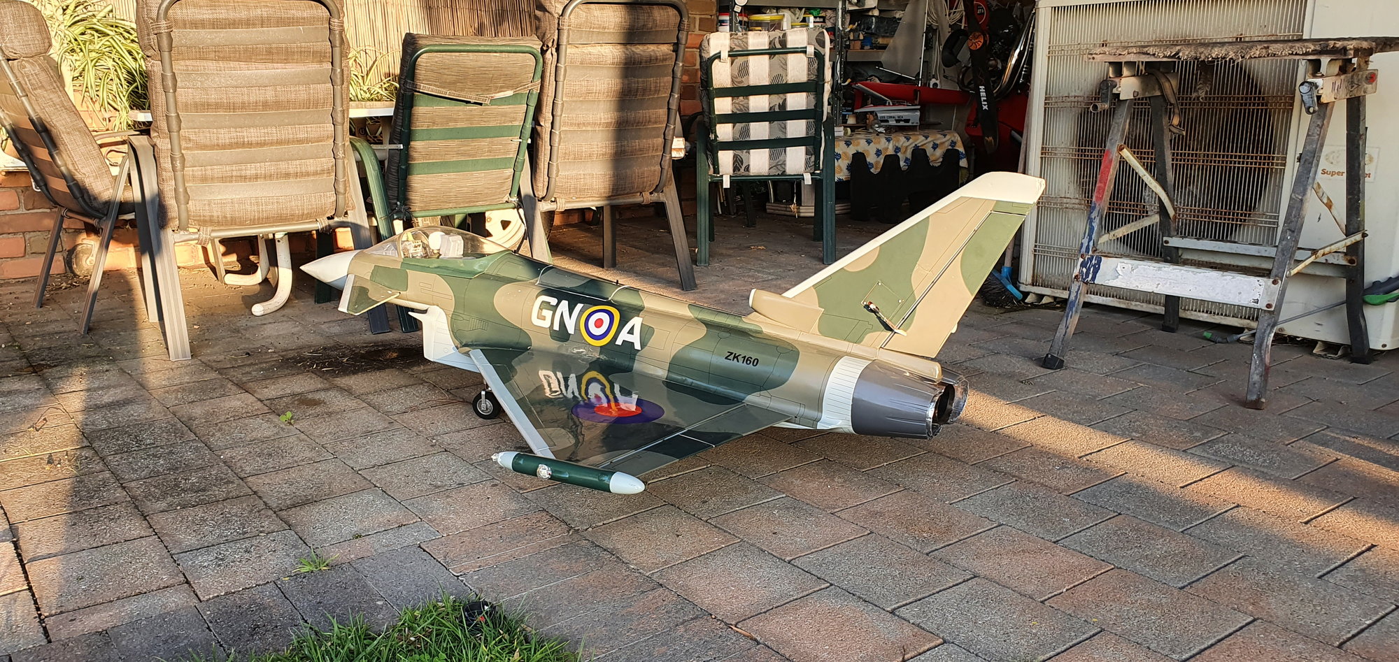
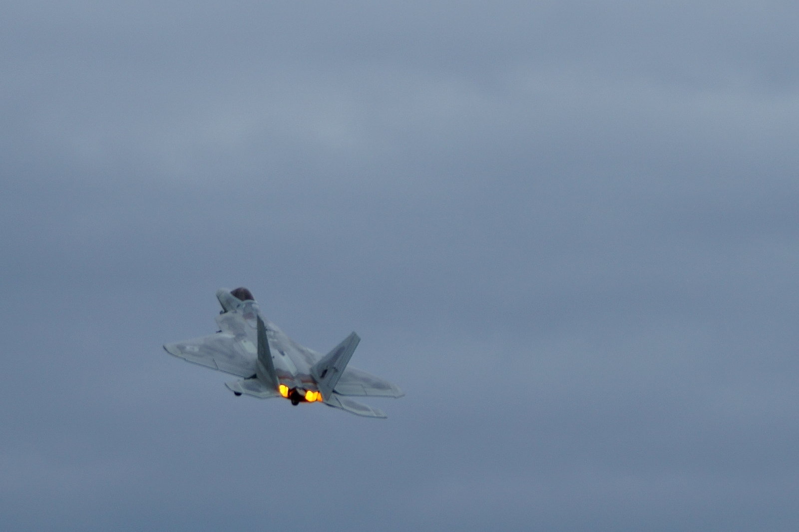
Gary, yet another amazing foamie jet conversion! I did a Blackhorse Eurofighter conversion using a single X45 and it flys very well. It is a similar size to my Blackhorse L39, which is also a pleasure to fly. One thing that would look amazing on your new jet would be centre burner lights either side of the single pipe, and for me they give great orientation when flying, plus they just look amazing!!
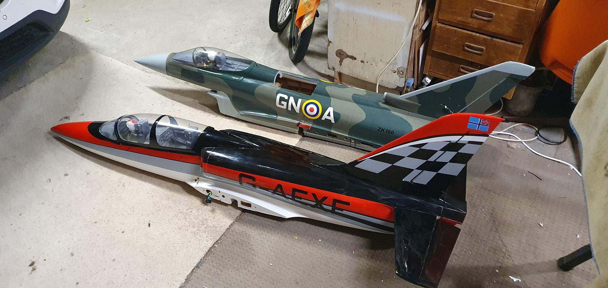
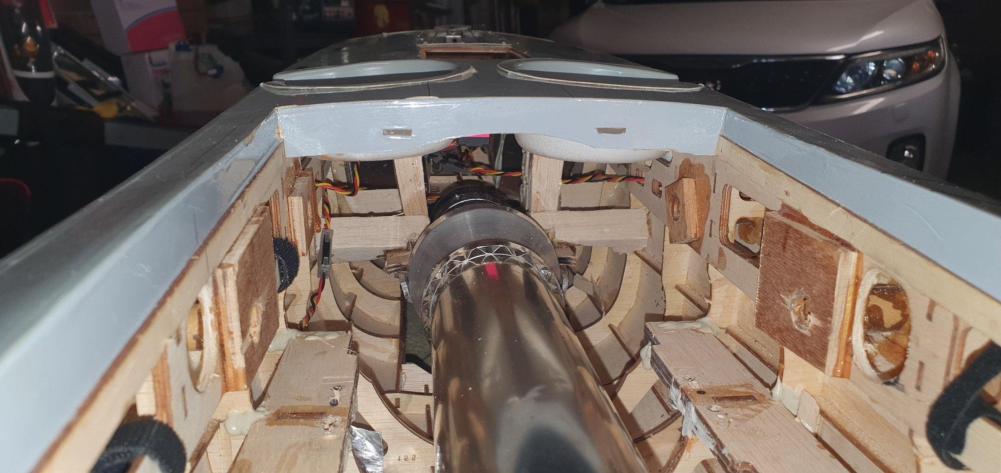
Single pipe cannot be seen when flying, screaming out for after burner lights!
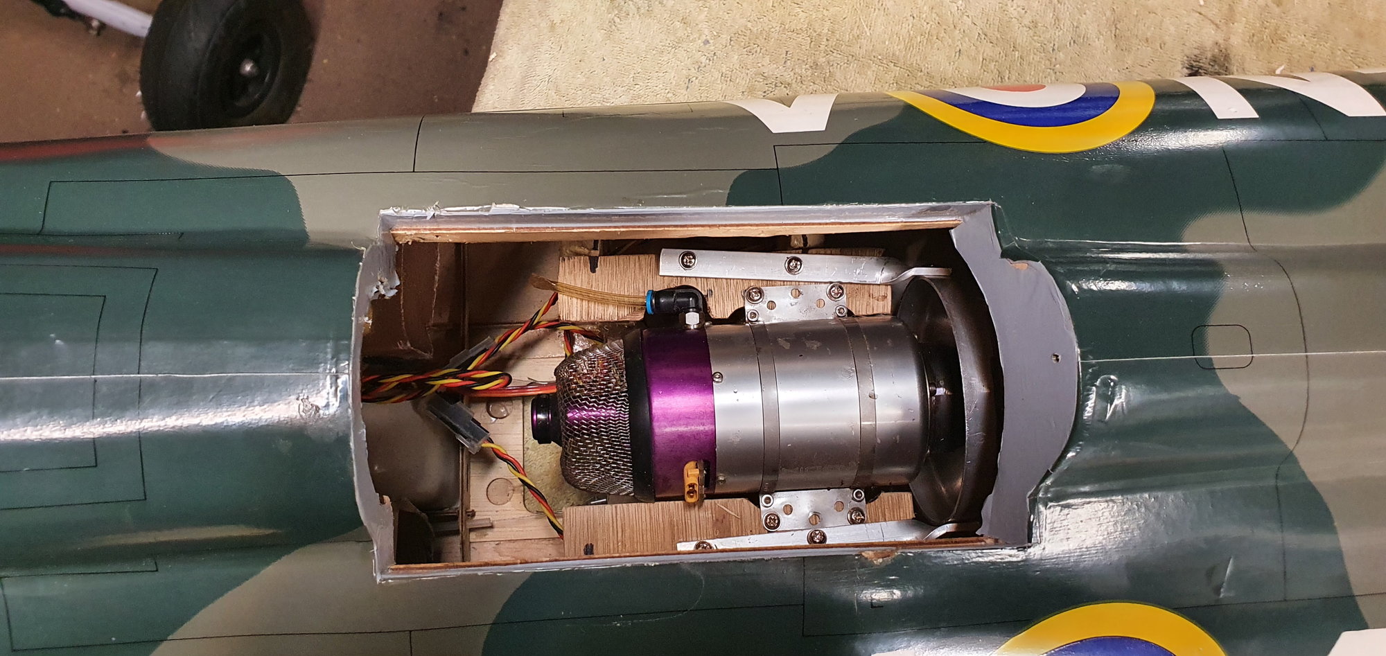
Lot's of room compared to the Freewing Euro.
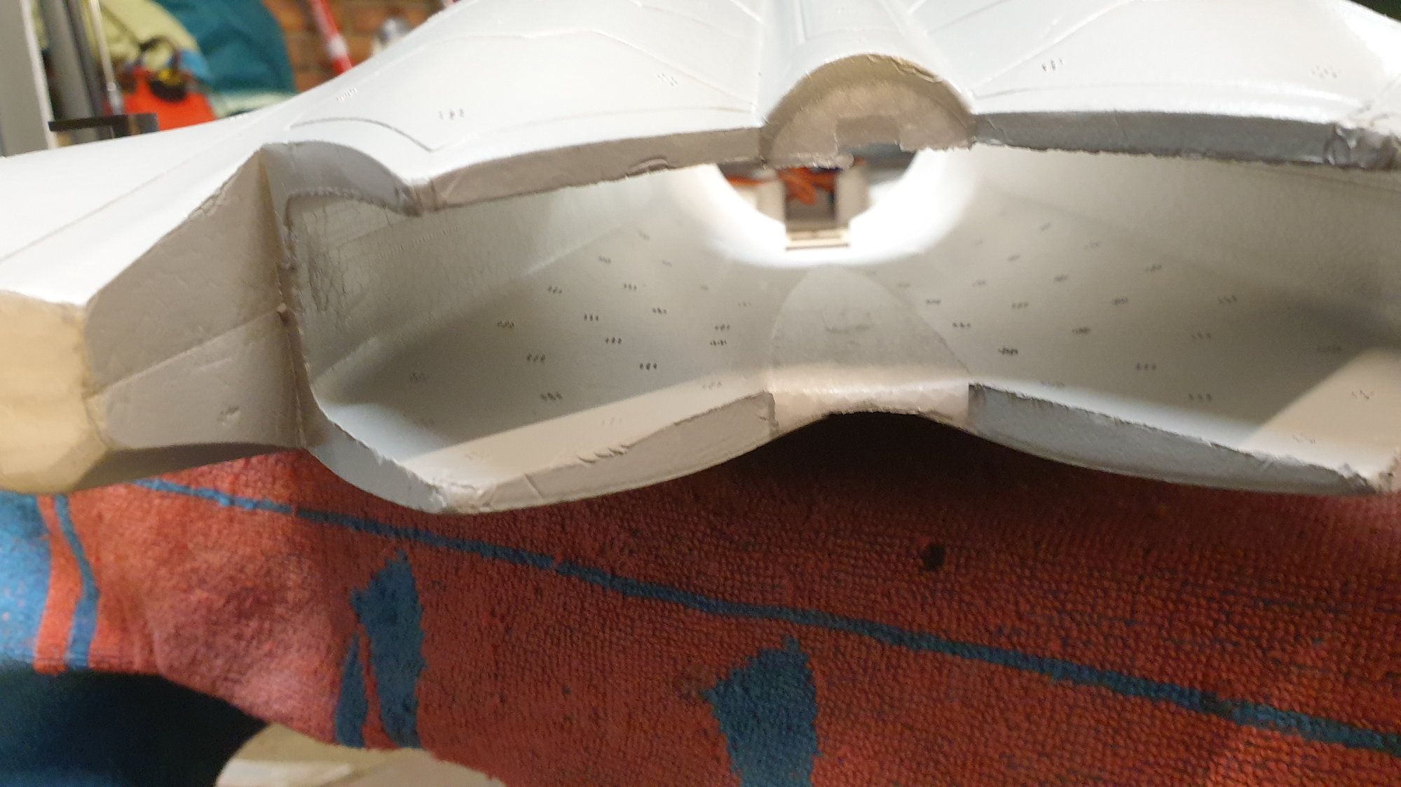
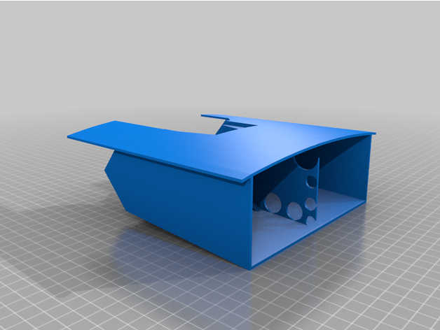
Centre duct removed using a serrated bread knife.
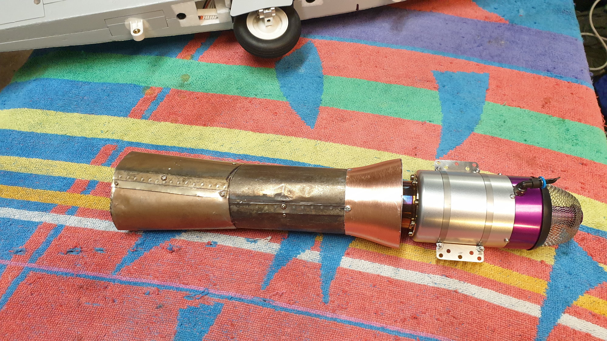
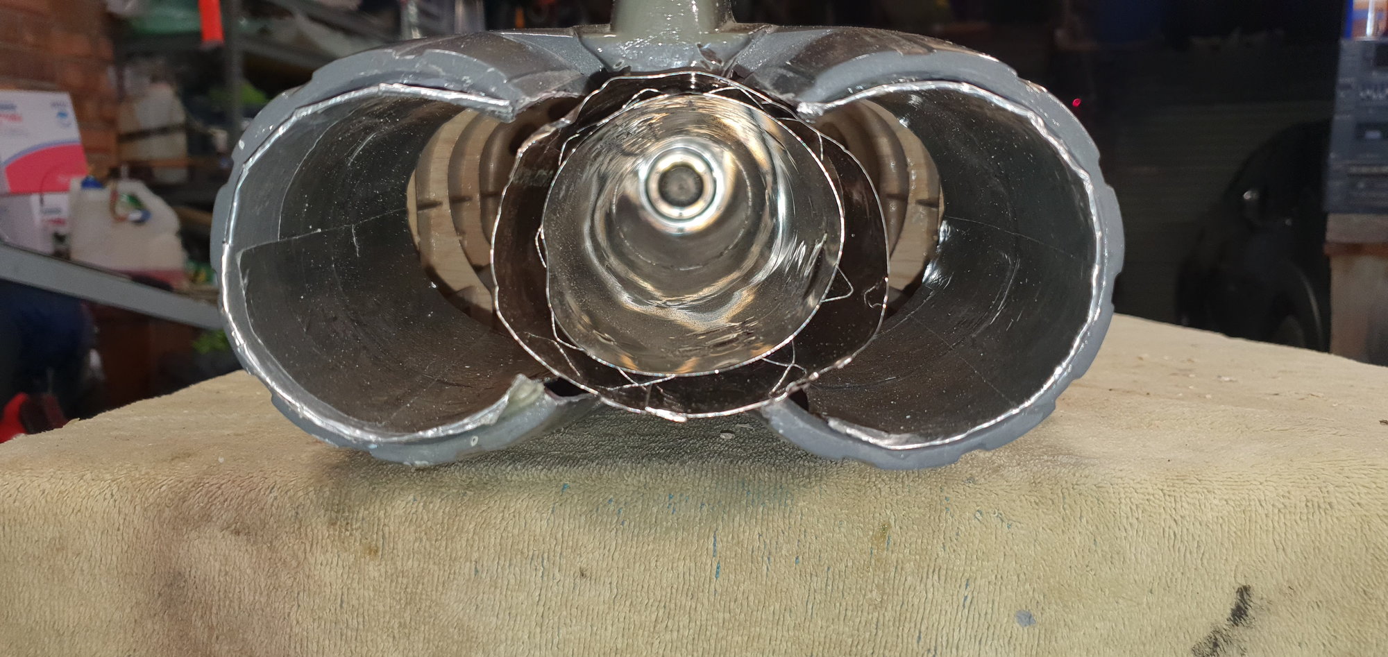
Home-made pipe, very easy to do with a cheap $40 spot welder.
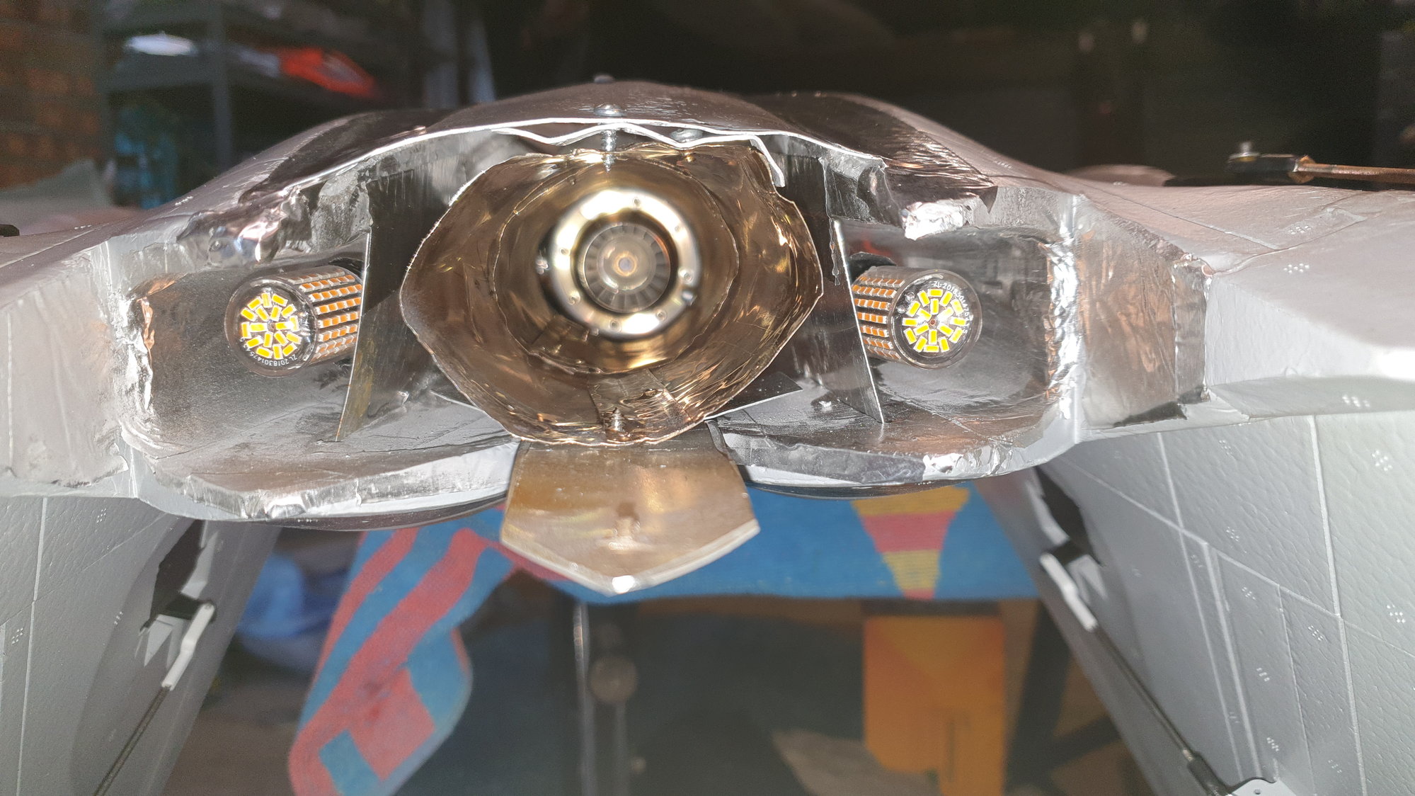
On my F22, some aluminium barriers keep the lights away from the pipe.
Lights help me with orientation.
Single pipe cannot be seen when flying, screaming out for after burner lights!
Lot's of room compared to the Freewing Euro.
Centre duct removed using a serrated bread knife.
Home-made pipe, very easy to do with a cheap $40 spot welder.
On my F22, some aluminium barriers keep the lights away from the pipe.
Lights help me with orientation.
05-07-2023, 06:10 AM
#37
Thread Starter
My Feedback: (20)
[QUOTE=Aussie1;12771730]Gary, yet another amazing foamie jet conversion! I did a Blackhorse Eurofighter conversion using a single X45 and it flys very well. It is a similar size to my Blackhorse L39, which is also a pleasure to fly. One thing that would look amazing on your new jet would be centre burner lights either side of the single pipe, and for me they give great orientation when flying, plus they just look amazing!!
Aussie, Thanks! I just thought of the AB lights last week myself. I think it is a great idea.
I am just now working on CG. I think I am close now but need to move battery as far forward as possible and also add fuel to the air trap tank and maybe possibly some ballast in the nose. It may take me another week for the CG since the Eurofighter is going to be "highjacked" by assembly of patio furniture and gazebo this week! Arrgh!
My plan would be to get the jet flying and then I can add some more bling like the Callie graphics and the AB lights.
Thanks, Gary
05-07-2023, 02:09 PM
#38
[quote=Viper1GJ;12771751]
On my FW F22, I hollowed out the nose cone and lined with light ply. This would fit two 2000ma 2s LiPo batteries and illiminated the lead in the nose, so as to balance. I'm very happy with the RC Castle centreburner light set, especially the cost compared to some others out there, just remove the heavy aluminium mount from them, that attaches the light to the EDF motor. Most of my pipes, I make as single wall and simply line the foam with aluminium tape. The fuselage seems to run very cool, but whether this is lighter than double wall pipes, is certainly debatable. https://www.rc-castle.com/index.php?...roduct_id=8885 Possibly, you may have seen this one already flying, but it certainly looks impressive, as I'm sure that yours will be too.
Gary, yet another amazing foamie jet conversion! I did a Blackhorse Eurofighter conversion using a single X45 and it flys very well. It is a similar size to my Blackhorse L39, which is also a pleasure to fly. One thing that would look amazing on your new jet would be centre burner lights either side of the single pipe, and for me they give great orientation when flying, plus they just look amazing!!
Aussie, Thanks! I just thought of the AB lights last week myself. I think it is a great idea.
I am just now working on CG. I think I am close now but need to move battery as far forward as possible and also add fuel to the air trap tank and maybe possibly some ballast in the nose. It may take me another week for the CG since the Eurofighter is going to be "highjacked" by assembly of patio furniture and gazebo this week! Arrgh!
My plan would be to get the jet flying and then I can add some more bling like the Callie graphics and the AB lights.
Thanks, Gary
05-07-2023, 03:31 PM
#39
Thread Starter
My Feedback: (20)
Hi Aussie1,
Thanks for the video link. I have seen several of his videos. His flies very well and I hope mine will too. I saw his video of the first turbine start on a stand and he stated in comments that it only had 650ml or 22oz of fuel. This makes most of his flights I've seen on video about 3 to 3.5 minutes. I was hoping to get 6-8 min. The CAD computer estimated volume for both of Keith's tanks is about1.18L or 40oz. This has been giving me 7-8 min on other jets with the X-45. We will see.
I've done the plywood box in the nose cone on some of my previous conversions and it will probably happen here too. I'll support the battery box from the fuse since I had trouble keeping some of the nose cones on during landings with the weight of the battery inside. I added some more magnets and they stayed on ok.
I like the idea of the AB lights. I have them in the MiG-29 and they look cool in flight. I'll take a look a the Castle lights.
Thanks for the ideas,
Gary
05-07-2023, 03:49 PM
#40
Thread Starter
My Feedback: (20)
Final items in progress
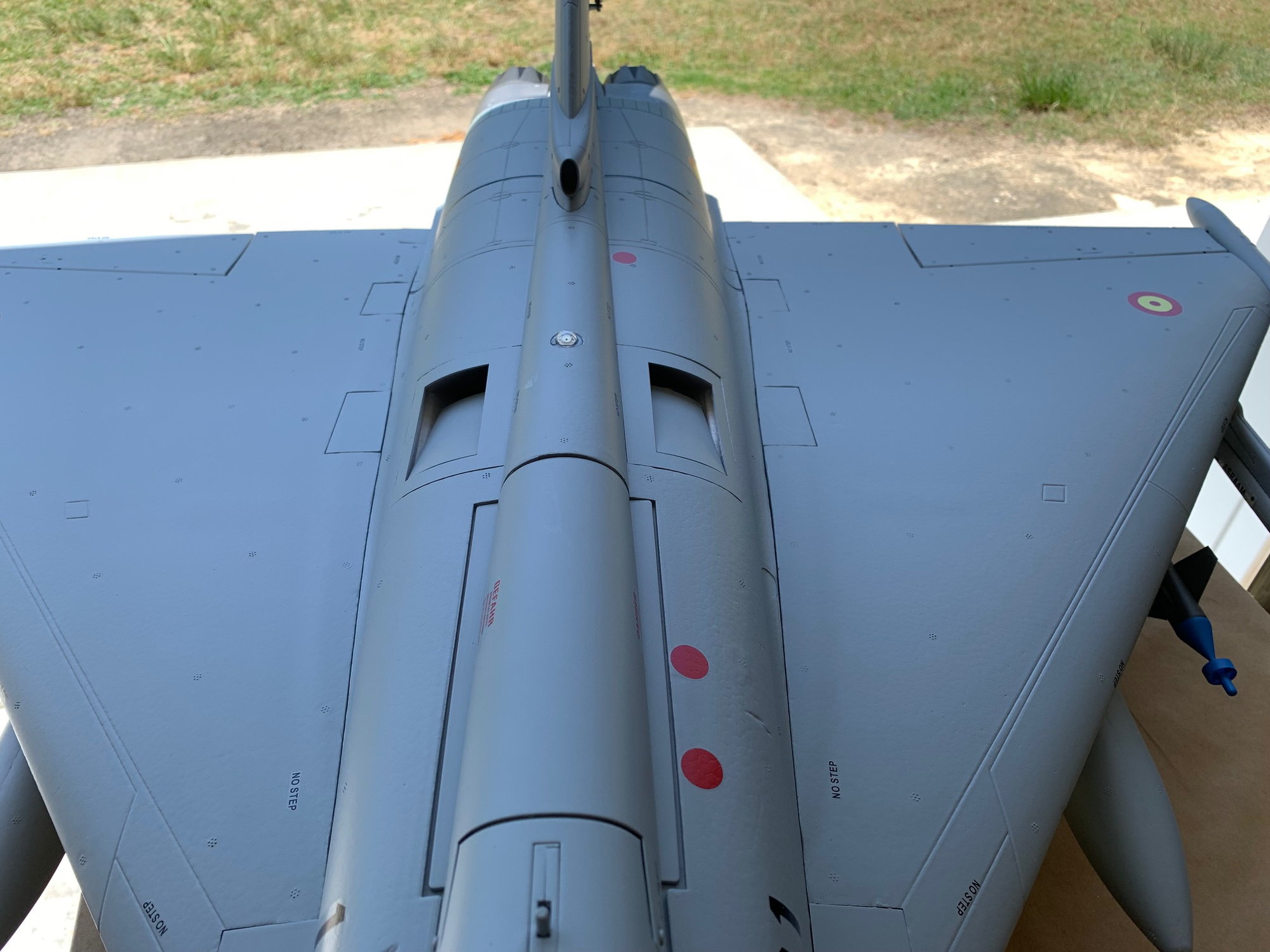
I attached all the Freewing eye candy on the wings. I plan to fly it with all the stuff most of the time.
Seems to be a mix load out with mostly air to air weapons but the blue LGBs look too cool to leave off.
Almost all the stuff is behind the CG so I'll have to compensate in the nose a little more. I plan to start with the CG at 30mm behind the wing marks with landing fuel based on info I've read in other forums. That will make the T.O. CG slightly forward of 30mm. The main tank has a "sight gage" on the front wall behind the nose wheel where you should be able to see the fuel level remaining in the tank. That's why I didn't paint the front wall.

Final shape of he ECM pod under the rudder to clear the pipe. It was coated with BVM Heat Shield and painted before being glued on.
Ribbon cables covered in turbine bay. Balsa side covers and strips of BVM Heat Blanket over the side and top slots.

Balsa side shields coated with BVM Heat Shield.
I attached all the Freewing eye candy on the wings. I plan to fly it with all the stuff most of the time.
Seems to be a mix load out with mostly air to air weapons but the blue LGBs look too cool to leave off.
Almost all the stuff is behind the CG so I'll have to compensate in the nose a little more. I plan to start with the CG at 30mm behind the wing marks with landing fuel based on info I've read in other forums. That will make the T.O. CG slightly forward of 30mm. The main tank has a "sight gage" on the front wall behind the nose wheel where you should be able to see the fuel level remaining in the tank. That's why I didn't paint the front wall.
Final shape of he ECM pod under the rudder to clear the pipe. It was coated with BVM Heat Shield and painted before being glued on.
Ribbon cables covered in turbine bay. Balsa side covers and strips of BVM Heat Blanket over the side and top slots.
Balsa side shields coated with BVM Heat Shield.
05-07-2023, 04:41 PM
#41
Hi Aussie1,
Thanks for the video link. I have seen several of his videos. His flies very well and I hope mine will too. I saw his video of the first turbine start on a stand and he stated in comments that it only had 650ml or 22oz of fuel. This makes most of his flights I've seen on video about 3 to 3.5 minutes. I was hoping to get 6-8 min. The CAD computer estimated volume for both of Keith's tanks is about1.18L or 40oz. This has been giving me 7-8 min on other jets with the X-45. We will see.
I've done the plywood box in the nose cone on some of my previous conversions and it will probably happen here too. I'll support the battery box from the fuse since I had trouble keeping some of the nose cones on during landings with the weight of the battery inside. I added some more magnets and they stayed on ok.
I like the idea of the AB lights. I have them in the MiG-29 and they look cool in flight. I'll take a look a the Castle lights.
Thanks for the ideas,
Gary
Thanks for the video link. I have seen several of his videos. His flies very well and I hope mine will too. I saw his video of the first turbine start on a stand and he stated in comments that it only had 650ml or 22oz of fuel. This makes most of his flights I've seen on video about 3 to 3.5 minutes. I was hoping to get 6-8 min. The CAD computer estimated volume for both of Keith's tanks is about1.18L or 40oz. This has been giving me 7-8 min on other jets with the X-45. We will see.
I've done the plywood box in the nose cone on some of my previous conversions and it will probably happen here too. I'll support the battery box from the fuse since I had trouble keeping some of the nose cones on during landings with the weight of the battery inside. I added some more magnets and they stayed on ok.
I like the idea of the AB lights. I have them in the MiG-29 and they look cool in flight. I'll take a look a the Castle lights.
Thanks for the ideas,
Gary
05-07-2023, 05:19 PM
#42
Thread Starter
My Feedback: (20)
I have two sets of the Castle lights now, the second set in the Blackhorse Euro, very happy with them, for the price. With the F22 nose cone, I epoxied some 6mm carbon tube into the fuselage, and then some 4mm carbon rod into the nose cone. This then slides into the tube, giving excellent support for the batteries, plus I left the magnets in place. It would be interesting to see how Frodo did his installation, especially the tank, because one litre is the minimum size tank for the X45, in my opinion. Your solution is equivalent to a full size new tank install, from a engineering point of view!!.
Agree 1L is minimum volume for x-45. That's why Keith made the rear aux tank as the main tank only had about .9L or 30oz.
Thanks for the tips,
Gary
05-09-2023, 02:59 AM
#43
Thread Starter
My Feedback: (20)
Keith posted the link for the 3D printed tanks on Thingiverse. You can download them here and print for yourself.
https://www.thingiverse.com/thing:6015555
https://www.thingiverse.com/thing:6015555
Last edited by Viper1GJ; 05-09-2023 at 03:08 AM.
The following 2 users liked this post by Viper1GJ:
dr.tom (06-16-2023),
jcterrettaz (05-10-2023)
05-09-2023, 04:51 PM
#44
Thread Starter
My Feedback: (20)
Moving battery to nose cone
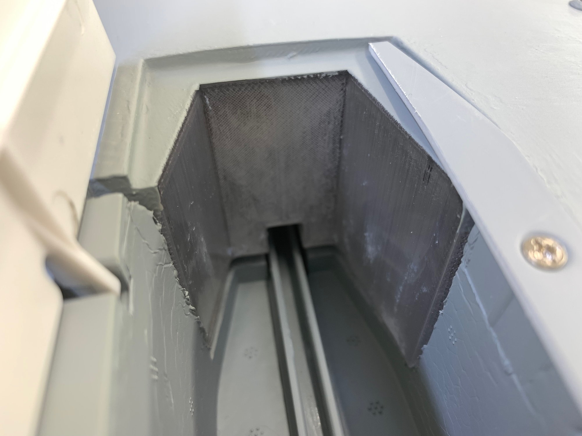
Here is the main fuel tank "sight gage". The front of the tank in the nose gear well should allow you to see the volume of fuel remaining in the tank. Hopefully it will work ok.
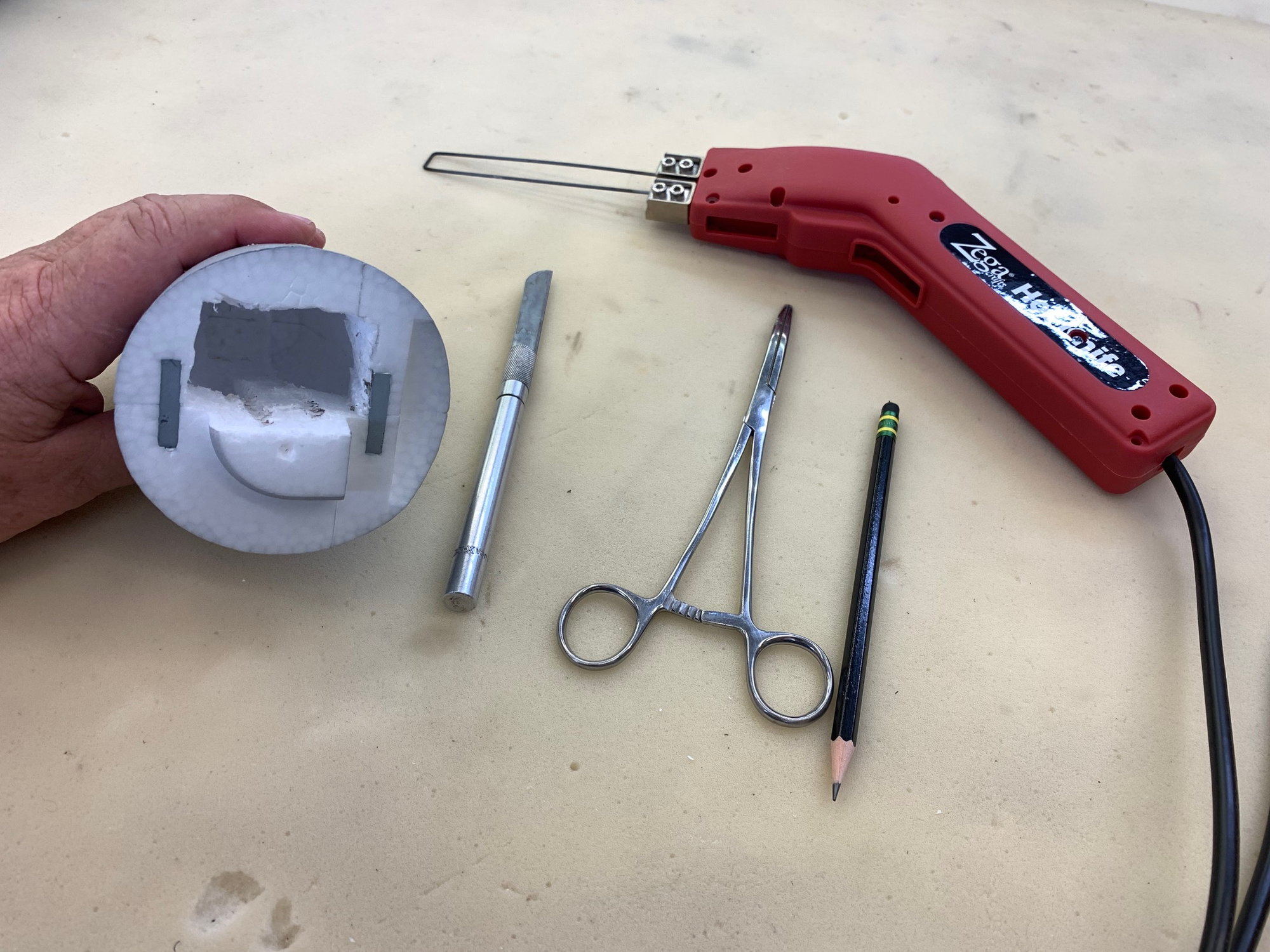
I used a hot wire cutter to open up the nose cone. A long hack saw blade would work here also.
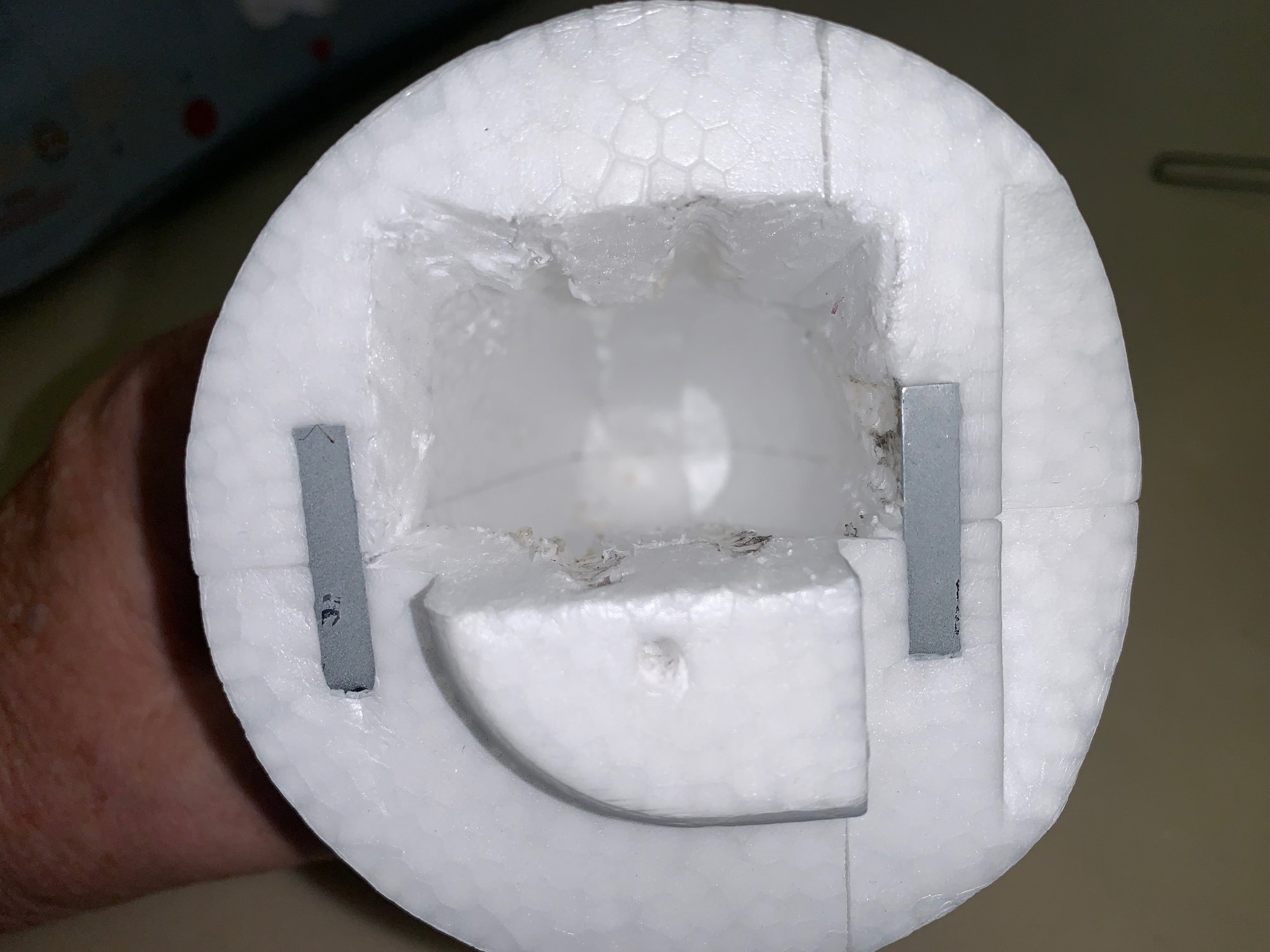
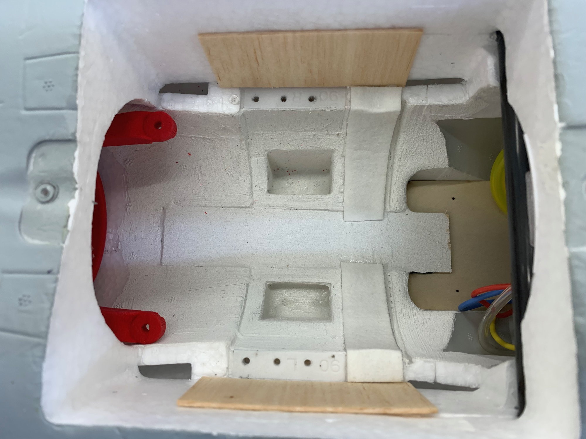
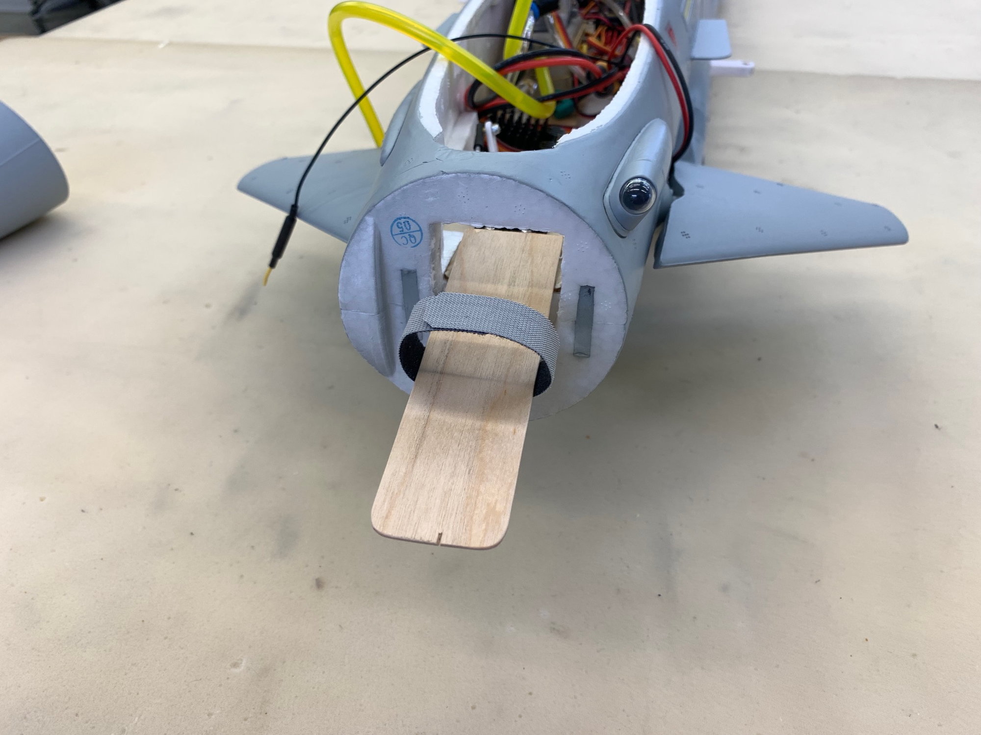
The nose cone is hollow after you cut through the rear face about 1" deep. It has a full length center rib about 1/2" thick that I removed. There is plenty of room for one or two batteries depending on how you set them up.
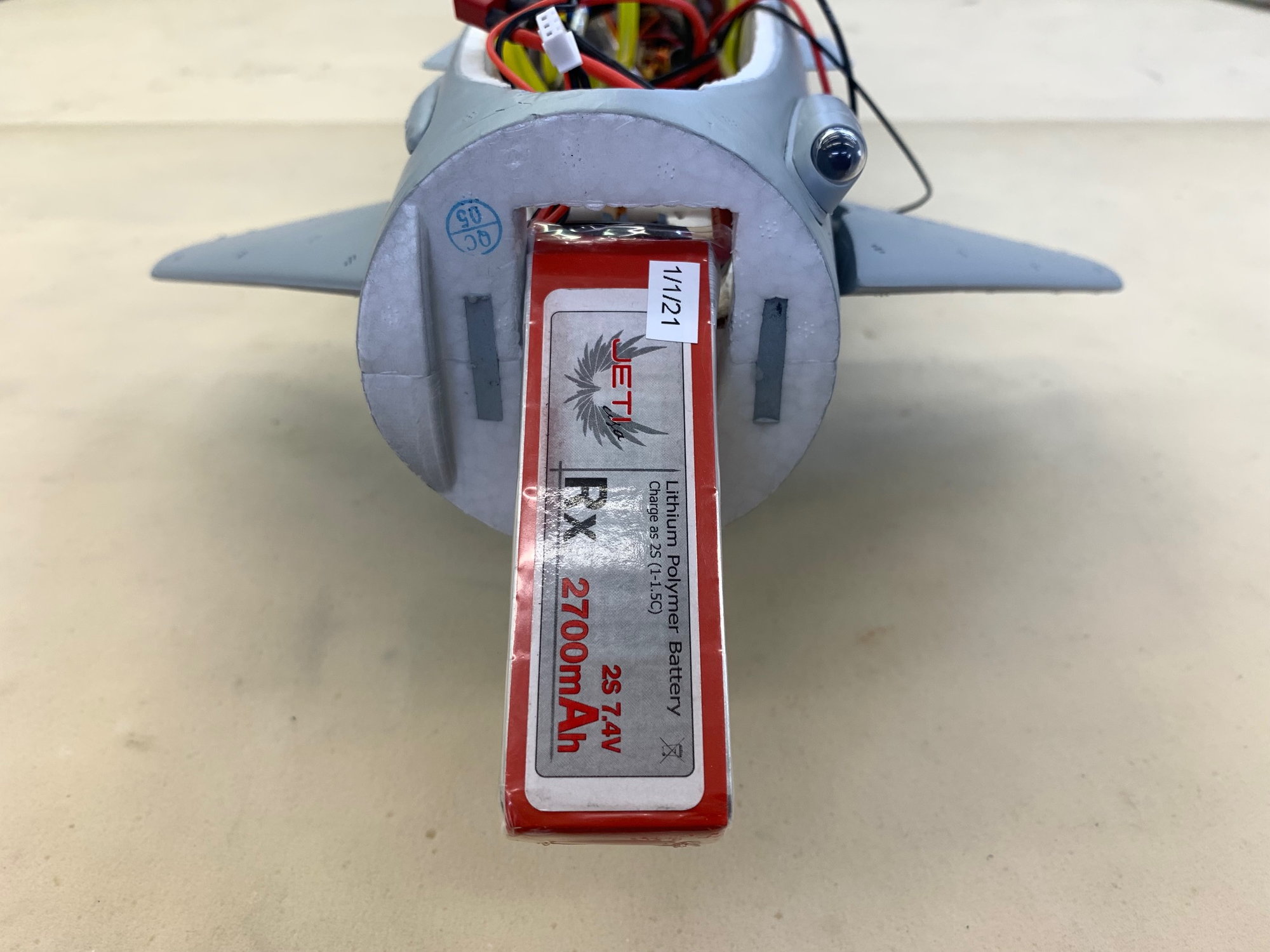
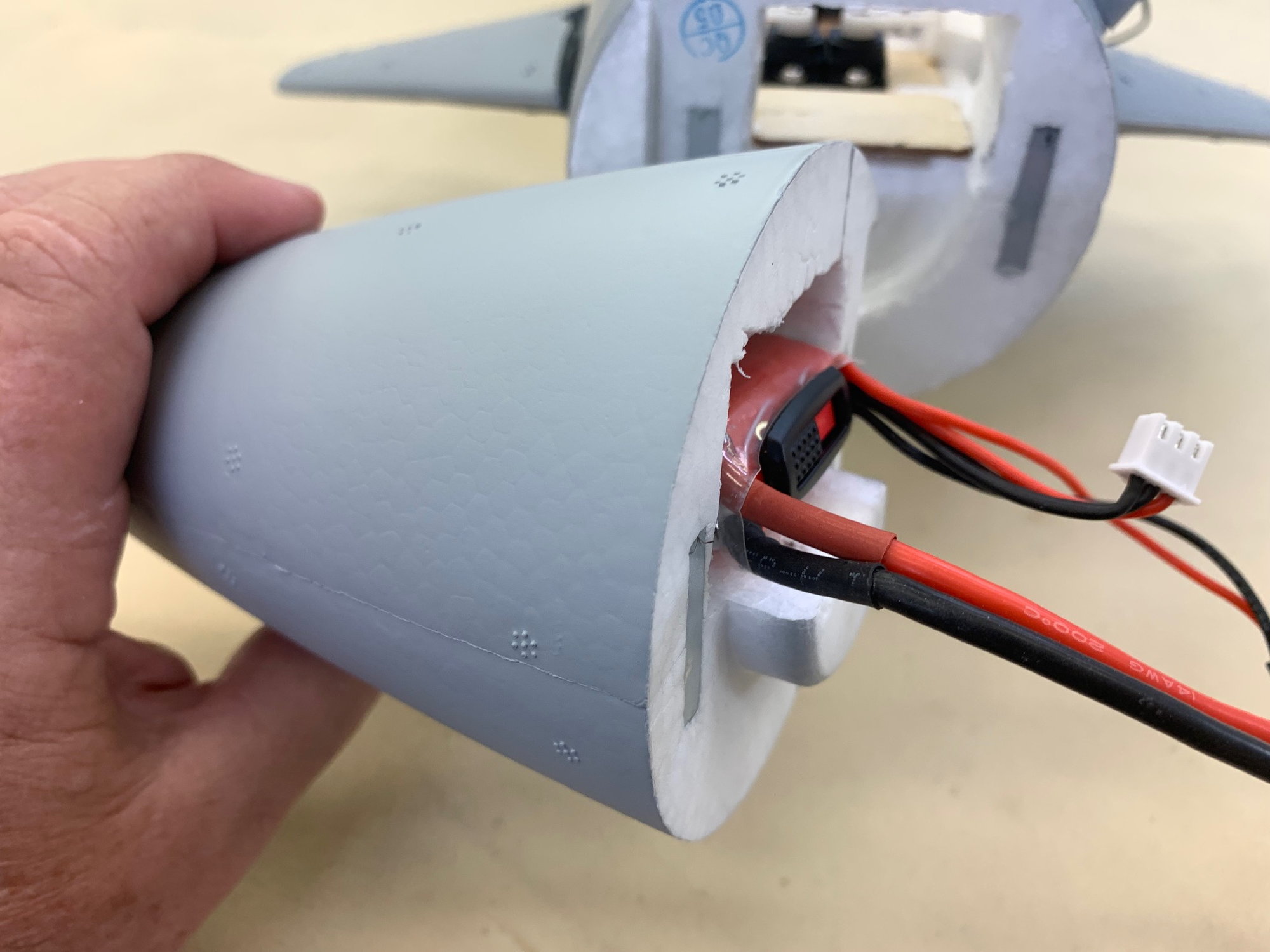
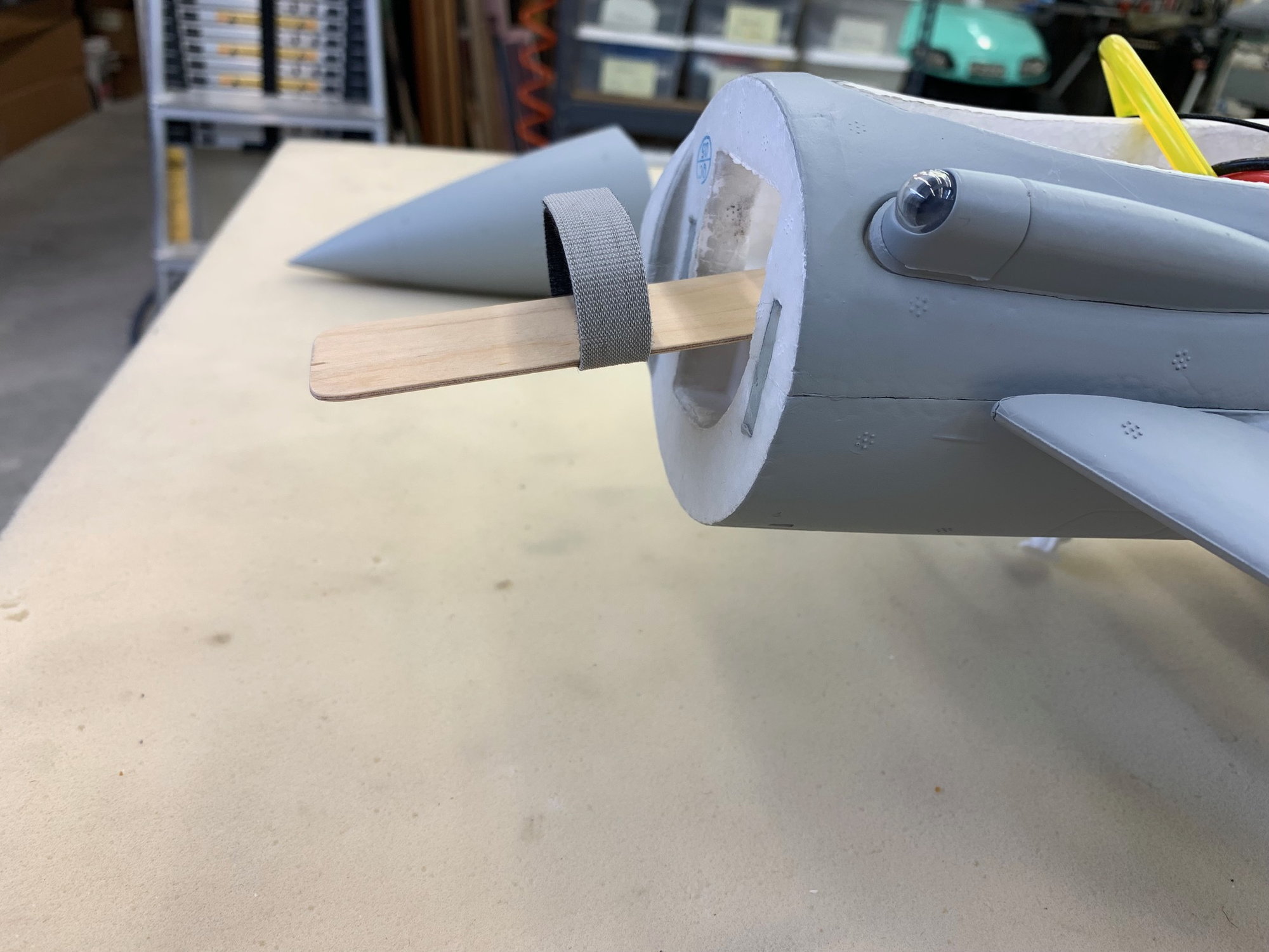
I made the front fuse hole wide enough for my batteries. I will epoxy a plywood tongue under the battery so the weight of the battery under G loads will be supported by the front fuse instead of the nose cone. With the battery installed the cone does not rotate at all and the magnets are enough to keep it on.
Entire battery can be placed in the nose cone.
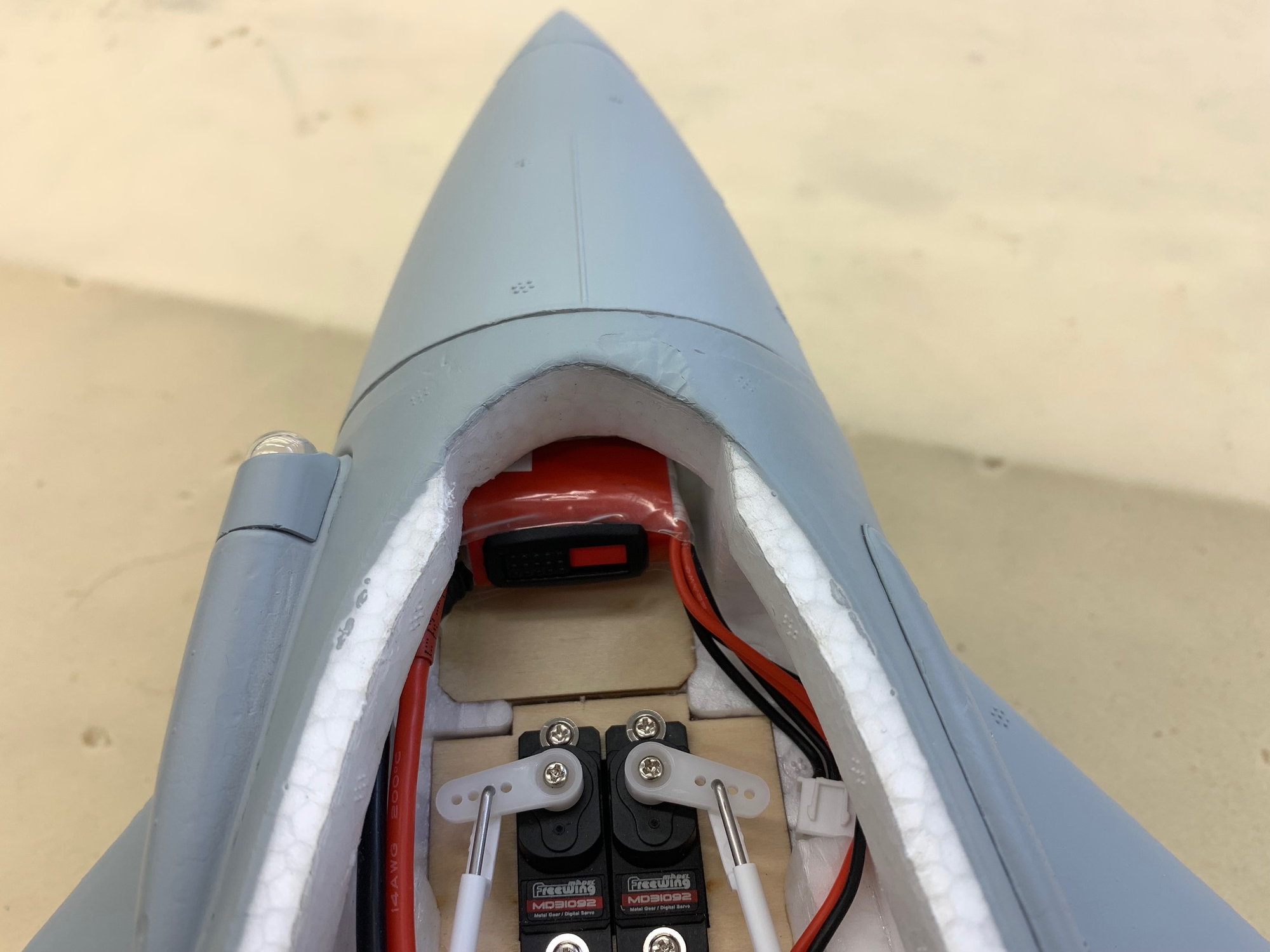
Easy access from inside.
Here is the main fuel tank "sight gage". The front of the tank in the nose gear well should allow you to see the volume of fuel remaining in the tank. Hopefully it will work ok.
I used a hot wire cutter to open up the nose cone. A long hack saw blade would work here also.
The nose cone is hollow after you cut through the rear face about 1" deep. It has a full length center rib about 1/2" thick that I removed. There is plenty of room for one or two batteries depending on how you set them up.
I made the front fuse hole wide enough for my batteries. I will epoxy a plywood tongue under the battery so the weight of the battery under G loads will be supported by the front fuse instead of the nose cone. With the battery installed the cone does not rotate at all and the magnets are enough to keep it on.
Entire battery can be placed in the nose cone.
Easy access from inside.
Last edited by Viper1GJ; 05-09-2023 at 04:54 PM.
05-09-2023, 05:33 PM
#45
I like the ply tongue support for the batteries, alot easier than my method of rods sliding into tubes. Amazing how much room inside the plastic nose cones once you cut into them!
The following users liked this post:
Viper1GJ (05-10-2023)
05-10-2023, 12:12 PM
#46
Thread Starter
My Feedback: (20)
Battery moved to nose cone
Plywood tray and thin Velcro for battery in nose cone.
Down angle keeps the battery in the center of the cone and not hitting the top or bottom inside edges.

Plywood tray epoxied to plywood in front of canard servos
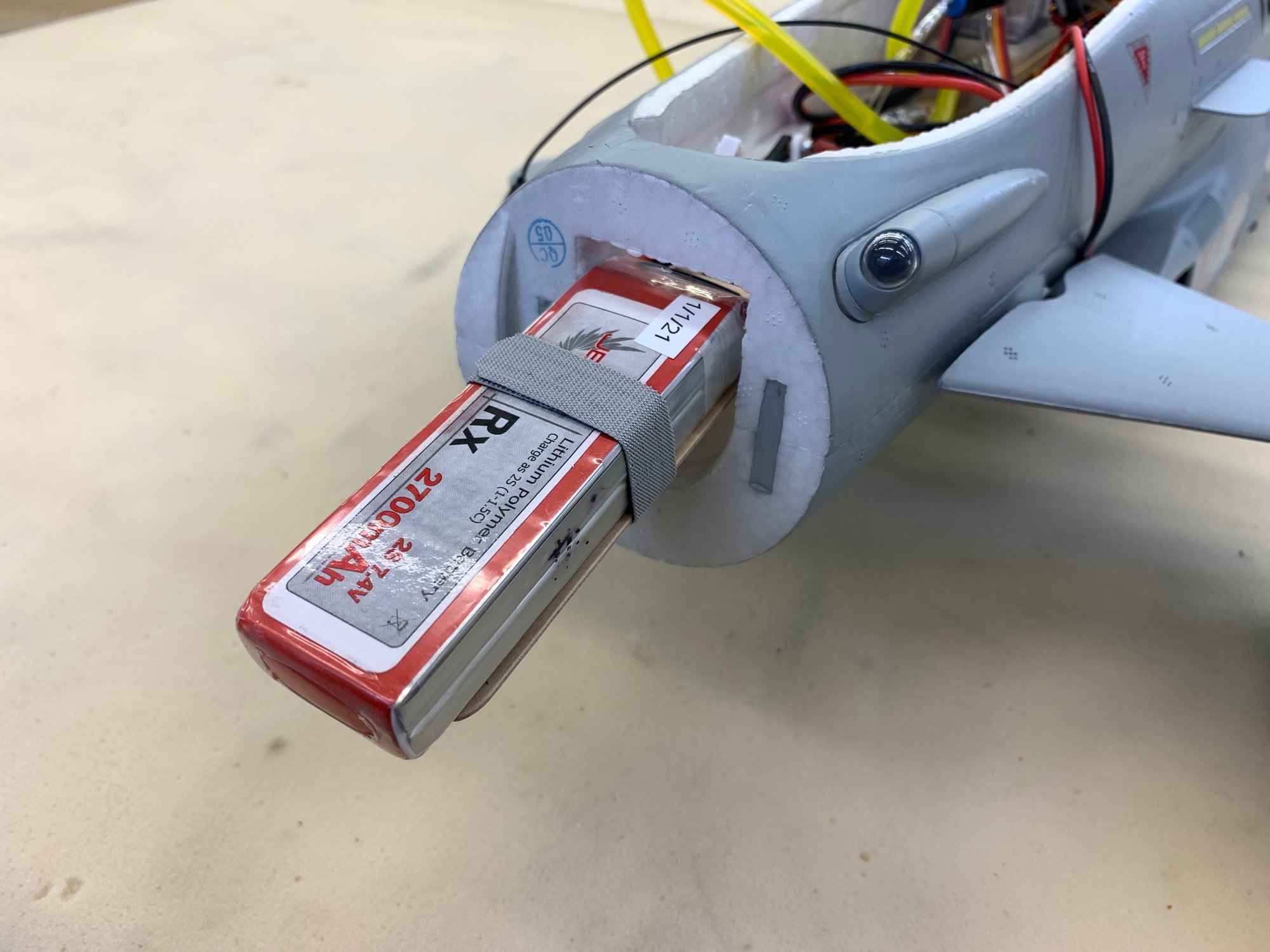
Battery strapped in.
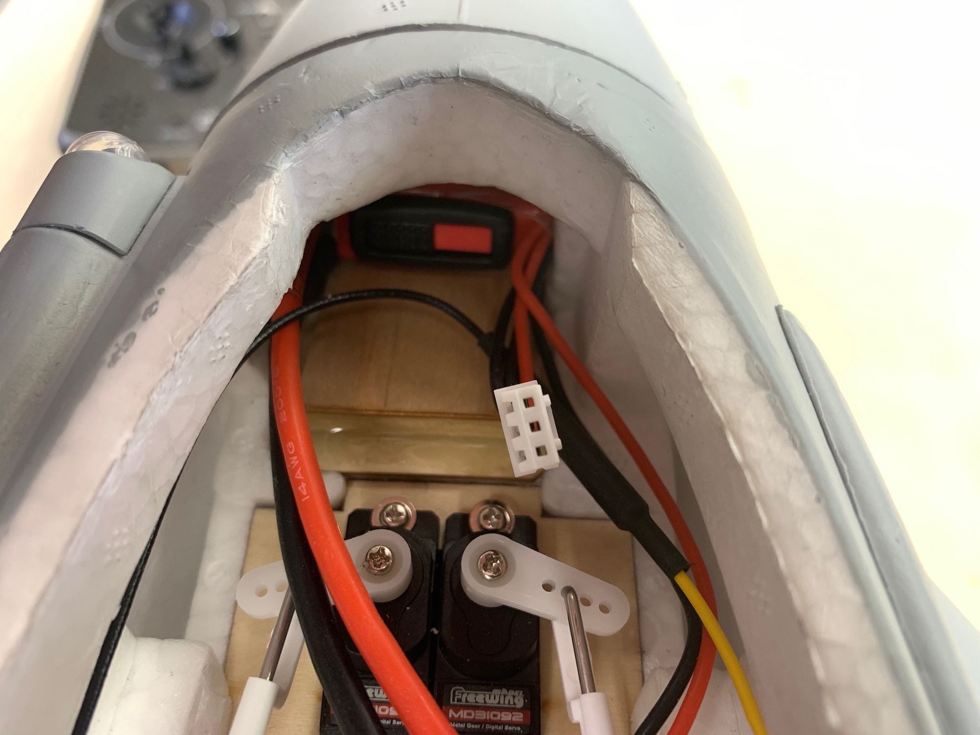
Battery had to be pushed forward to clear the forward foam hook on the canopy.
Plywood tray and thin Velcro for battery in nose cone.
Down angle keeps the battery in the center of the cone and not hitting the top or bottom inside edges.
Plywood tray epoxied to plywood in front of canard servos
Battery strapped in.
Battery had to be pushed forward to clear the forward foam hook on the canopy.
05-10-2023, 12:57 PM
#47
Thread Starter
My Feedback: (20)
Weight and Balance

Xicoy CG Machine blue tooth to iPad works well for measuring and adjusting CG. The lines on the table are where I use a T-square to mark location of landing gear and CG locations relative to the gear. (There have been lots of jets measured on this table.) The distance between the mains and nose gear and the distance the desired CG is forward of the main gear are entered into the system. The system then gets weight on each gear and calculates the actual CG relative to the desired CG. Then you can move stuff around and try to get the desired CG. Once I get the desired CG I always fill the tanks to get the take off weight and CG. Then I defuel and make sure the CG is still acceptable as fuel is removed. When the tank is not exactly on the CG it is valuable to know how the CG shifts with fuel burn.
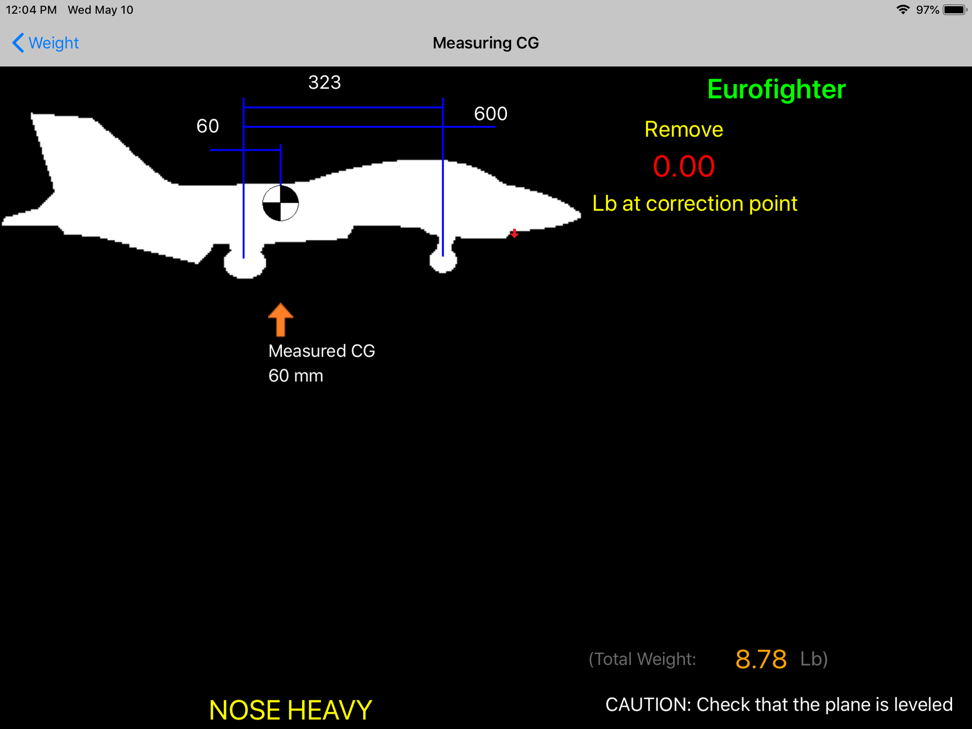
This is the empty weight with full air trap, all external ordinance, and 1.25oz or 35g of lead weight in the nose cone. The factory CG marked on the bottom of the bottom of the wings is 90mm forward of the mains. The CG here shows 60mm forward of the main gear which is my desired CG. This CG is 30mm behind the marks which is where I will start based on multiple reports in other forums. Some of the EDF guys are flying at 40-50mm behind the factory marks so I will fly first and probably remove some of the nose weight after that.

This is take off weight with all tanks full. CG moves forward 4mm which is completely acceptable. As the aft tank empties the CG shifts 6mm forward when the front tank is full. As the front tank empties the CG moves back to toward 60mm. I expect landing CG will be 61-63mm forward of the mains. Looks good to me for a safe flight. After the first flight CG can be adjusted as necessary.
Xicoy CG Machine blue tooth to iPad works well for measuring and adjusting CG. The lines on the table are where I use a T-square to mark location of landing gear and CG locations relative to the gear. (There have been lots of jets measured on this table.) The distance between the mains and nose gear and the distance the desired CG is forward of the main gear are entered into the system. The system then gets weight on each gear and calculates the actual CG relative to the desired CG. Then you can move stuff around and try to get the desired CG. Once I get the desired CG I always fill the tanks to get the take off weight and CG. Then I defuel and make sure the CG is still acceptable as fuel is removed. When the tank is not exactly on the CG it is valuable to know how the CG shifts with fuel burn.
This is the empty weight with full air trap, all external ordinance, and 1.25oz or 35g of lead weight in the nose cone. The factory CG marked on the bottom of the bottom of the wings is 90mm forward of the mains. The CG here shows 60mm forward of the main gear which is my desired CG. This CG is 30mm behind the marks which is where I will start based on multiple reports in other forums. Some of the EDF guys are flying at 40-50mm behind the factory marks so I will fly first and probably remove some of the nose weight after that.
This is take off weight with all tanks full. CG moves forward 4mm which is completely acceptable. As the aft tank empties the CG shifts 6mm forward when the front tank is full. As the front tank empties the CG moves back to toward 60mm. I expect landing CG will be 61-63mm forward of the mains. Looks good to me for a safe flight. After the first flight CG can be adjusted as necessary.
Last edited by Viper1GJ; 05-10-2023 at 03:53 PM.
05-10-2023, 03:02 PM
#48
Thread Starter
My Feedback: (20)
Turbine Test Runs - Good News...Bad News...
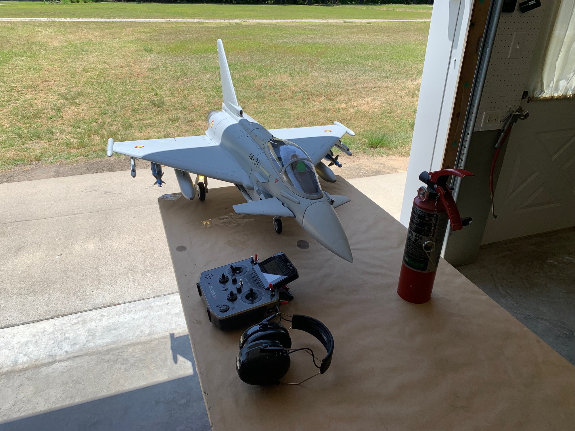
Jet gassed up and ready for turbine starts and run ups. Good news...X-45 starts up and runs perfectly. I did two starts with runups to max power and extended runs at idle. There were no indications of any heat damage inside or out. I think the pipe, bell mouth, and pipe tail mounts are working well. There seems to be plenty of airflow in and around the turbine bay and aft fuse for heat removal. I expected this would be the case since there is plenty of room around the turbine and pipe inside the fuse.
The top cheater holes would start to open at about 1/2 stick and never fully opened even at max power. I expect with flying airspeed going into the intake to raise internal air pressure the doors may not open in flight at all.
Bad news...on both shutdowns the electric motor would not stay engaged to the turbine to spin the rotor. It made strange noises and RPM would flux between 0 and 5000 rpm. Also the bottom of the turbine was wet with fuel that dripped out of the hatch. I think there may be a small fuel leak in the front under the cowl that is getting on the clutch and causing slippage but really don't know. It happened the same on both runs. This photo is after the 2nd run. The wet fuel has been wiped off but I don't know where it is coming from. I trimmed and reseated the fuel tube in the Festo fitting after the first run but still had fuel drips after the 2nd run same as the first. I have 4 X-45s and this is the first issue with any of them.
Ideas anyone?
Last edited by Viper1GJ; 05-10-2023 at 03:04 PM.
05-11-2023, 11:37 AM
#49
Thread Starter
My Feedback: (20)
Turbine cooling issue fixed.
I followed a suggestion from David WS on Facebook and guidance from Keith at Fenderbean RC and fixed the cooling issue. I suspected the rubber O ring was slipping during the cool down. David said he had the same issue and took off the motor and cleaned it up to solve the problem. Keith told me how to do it and it was a simple process.
It requires a small star bit to remove the three starter motor bolts. I made a wood pick from a popsicle stick to avoid nicking the O ring.
I cleaned the O ring and turbine rotor bullet nose nut with alcohol and a cotton swab. This pic shows just what was cleaned off the turbine rotor nut. The inside of the cowl looked clean and dry so I'm not sure where the drips I saw are coming from. Reassembly, install, and test run showed cool down works perfect now. I still have the fuel drip from somewhere.
05-11-2023, 12:04 PM
#50
Thread Starter
My Feedback: (20)
Final Items and Programming
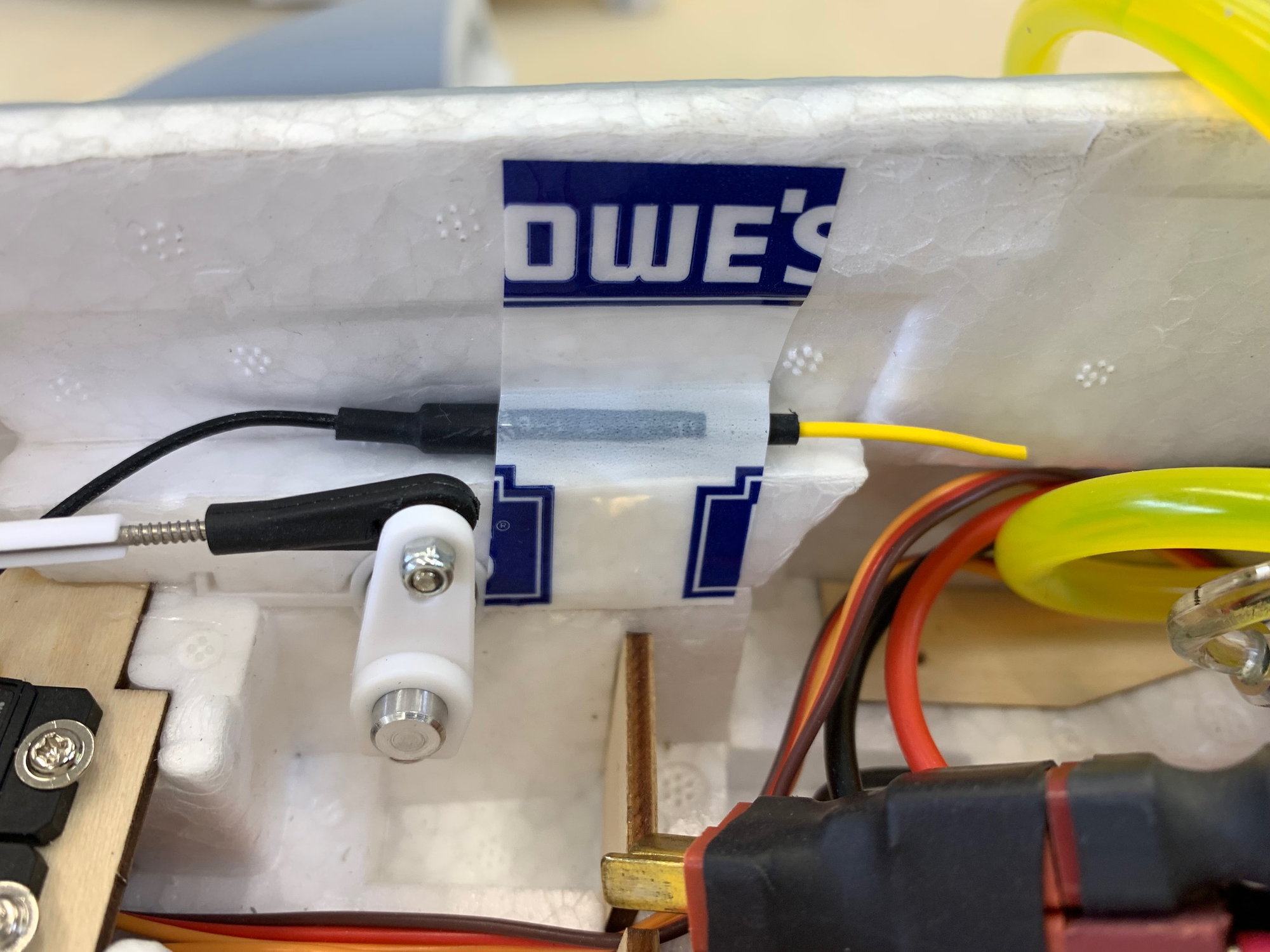
Jeti antennas were routed and taped in pace using Tevyk house tape. This one horizontal.
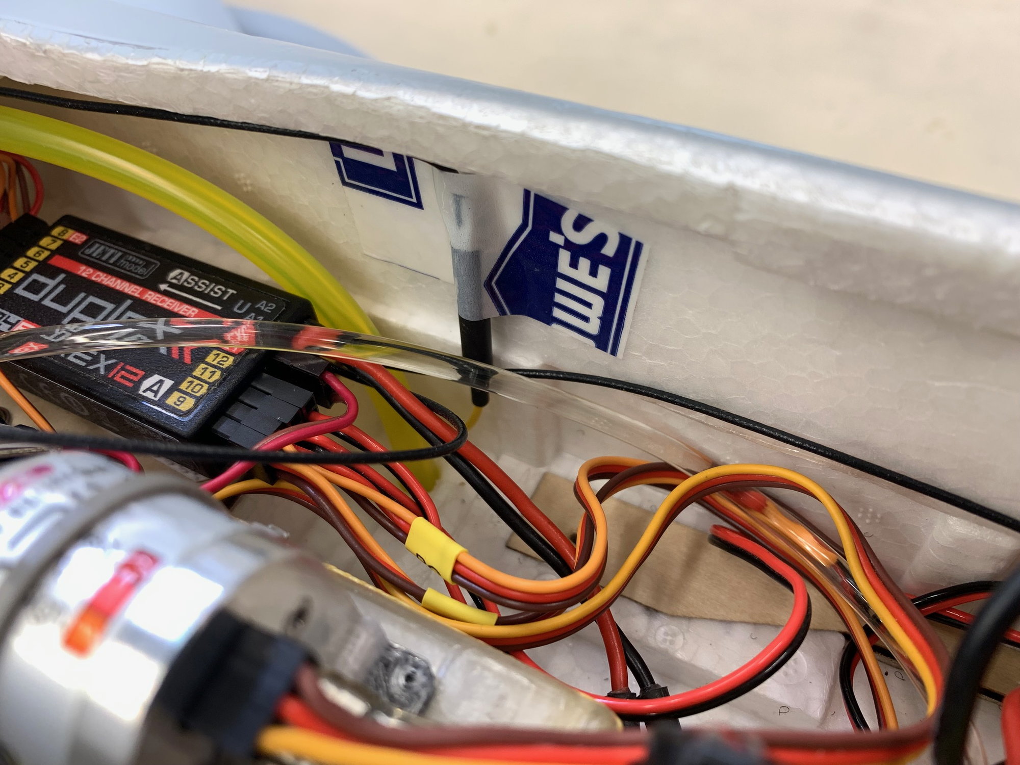
This one vertical.
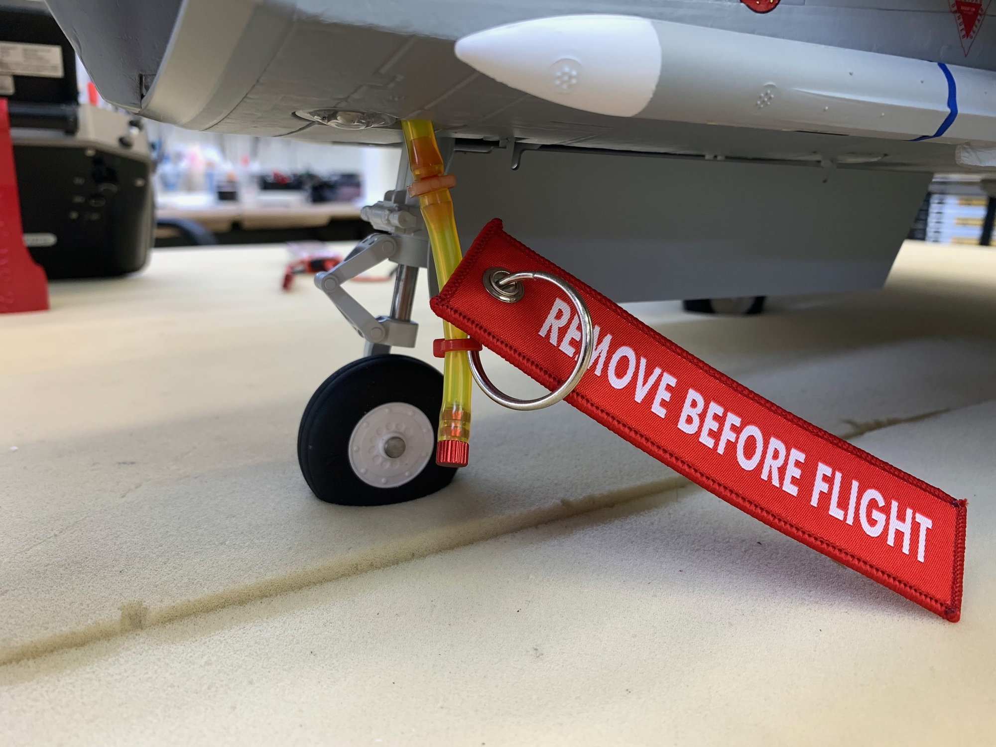
Vent tube plug installed for use when needing to turn the jet upside down.
I moved the Castle Pro BEC to the left side to better fit battery hook up wires and put the last grey paint bling on the battery tray. Build is complete.
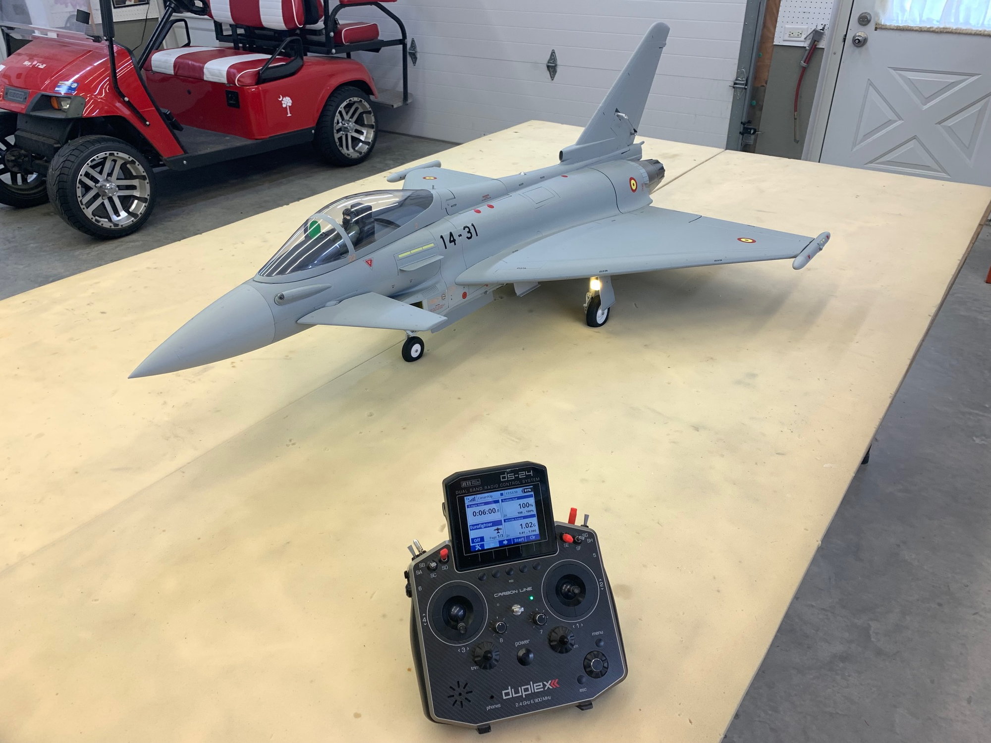
Final Jeti radio programming checks completed and all servos adjusted. The Jeti Assist gyro is selectable to ON and OFF in normal dampening mode. The gains for pitch, roll, and yaw are adjustable in flight by a rotary knob. Once desired gains are found and set they will be transferred to a fixed function curve and the knob disabled. All the flight controls are conventional with high and low rates except for the canards.
The canards are selectable to ON and OFF. When ON they are selectable for PITCH only or PITCH and ROLL together controlled by the right stick which controls the elevons. In addition the canards can be controlled by the flap switch to operate like 3 position "nose flaps" by dropping the trailing edge. UP is neutral, HALF is about 5mm trailing edge drop, and FULL is about 10mm drop. The canards can also be trimmed separately in pitch.
Test flight is scheduled for tomorrow morning. To be continued...
Jeti antennas were routed and taped in pace using Tevyk house tape. This one horizontal.
This one vertical.
Vent tube plug installed for use when needing to turn the jet upside down.
I moved the Castle Pro BEC to the left side to better fit battery hook up wires and put the last grey paint bling on the battery tray. Build is complete.
Final Jeti radio programming checks completed and all servos adjusted. The Jeti Assist gyro is selectable to ON and OFF in normal dampening mode. The gains for pitch, roll, and yaw are adjustable in flight by a rotary knob. Once desired gains are found and set they will be transferred to a fixed function curve and the knob disabled. All the flight controls are conventional with high and low rates except for the canards.
The canards are selectable to ON and OFF. When ON they are selectable for PITCH only or PITCH and ROLL together controlled by the right stick which controls the elevons. In addition the canards can be controlled by the flap switch to operate like 3 position "nose flaps" by dropping the trailing edge. UP is neutral, HALF is about 5mm trailing edge drop, and FULL is about 10mm drop. The canards can also be trimmed separately in pitch.
Test flight is scheduled for tomorrow morning. To be continued...
Last edited by Viper1GJ; 05-11-2023 at 01:51 PM.