


Turbine Conversion Of Freewing 90mm Eurofighter
 05-12-2023, 03:18 PM
#51

Thread Starter
My Feedback: (20)
First Flight Successful!
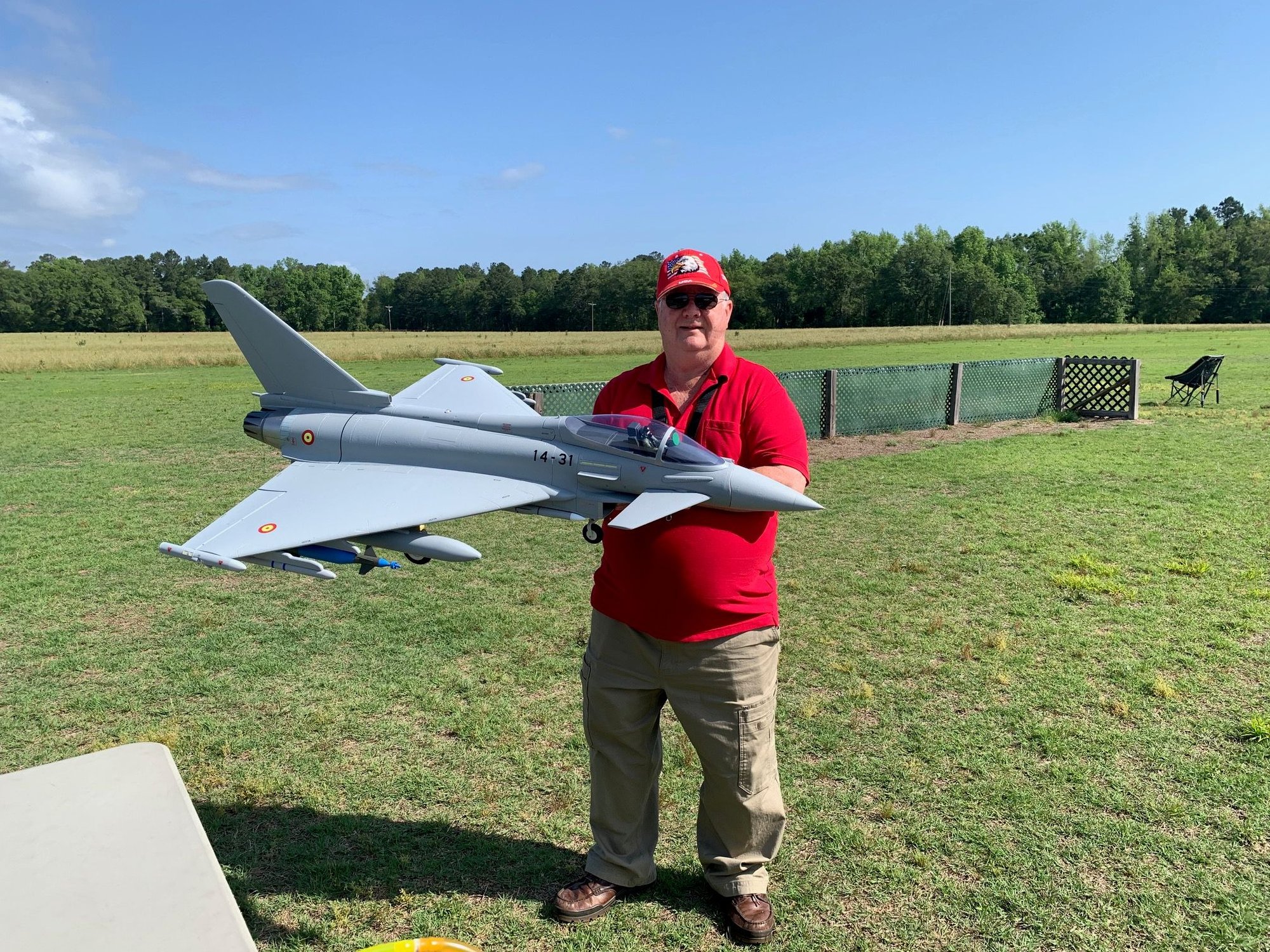
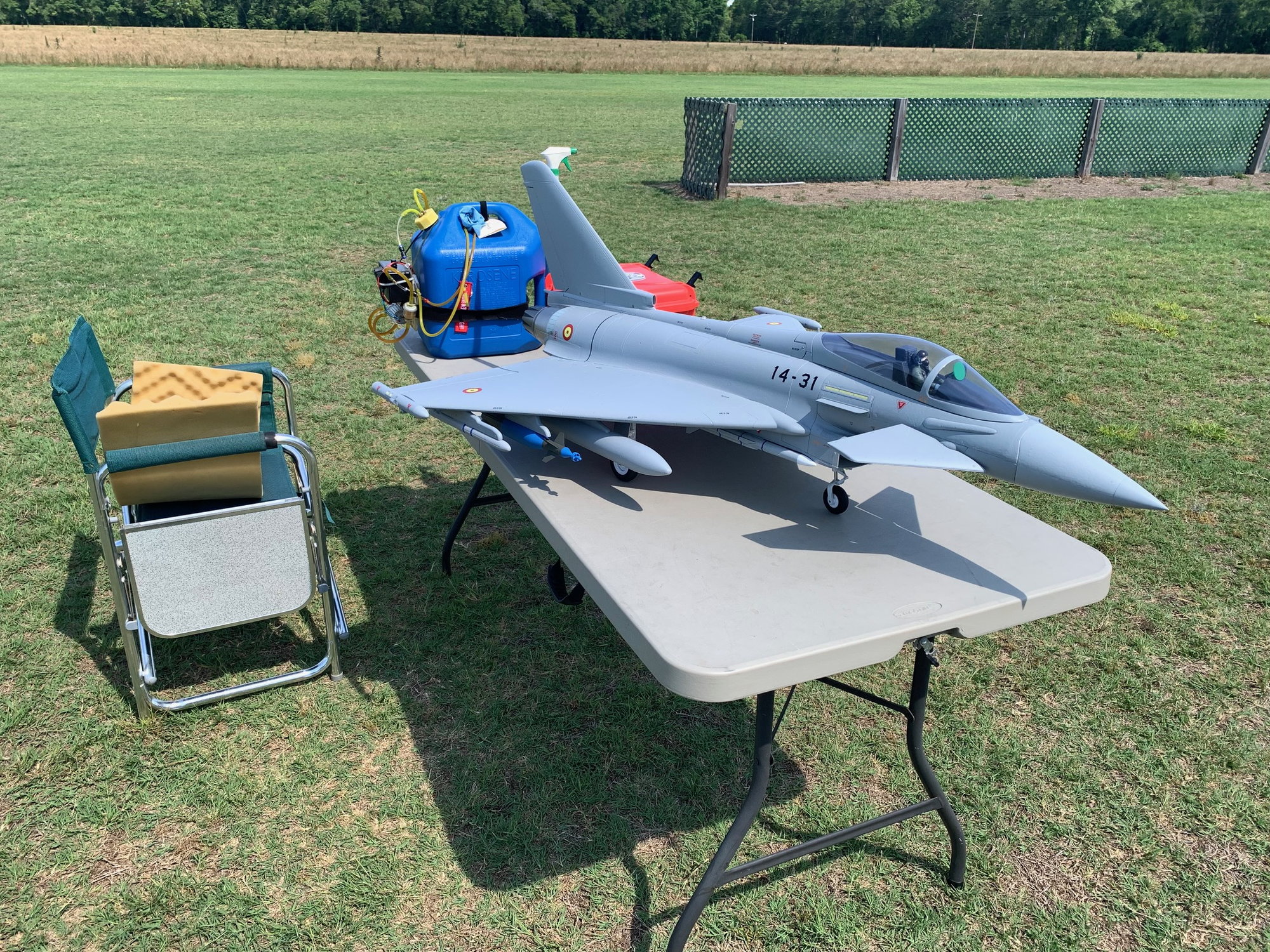
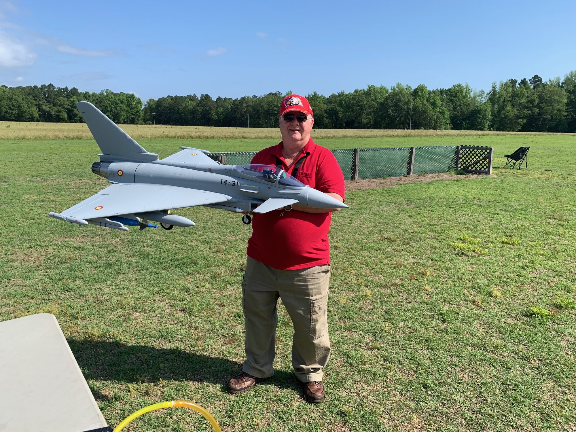
Some Happy Snaps before engine start.

Was a perfect day for test flight.
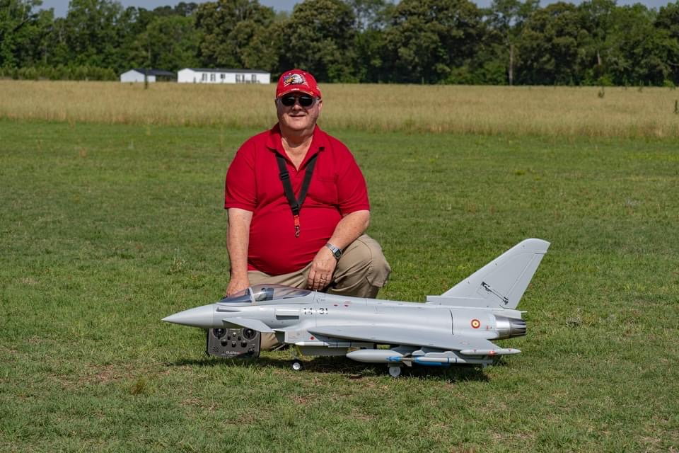
Should have waited for another hour and the runway grass was mowed. But we bumped on out and took off.
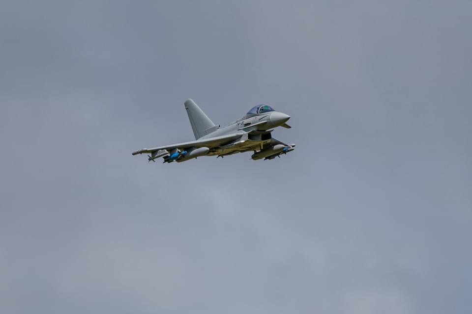
My friend Gary had his super camera out today and got the video and these inflight photos.
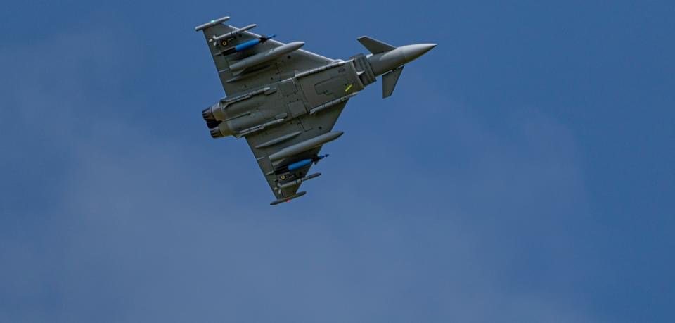
Good shot of all the under wing bling.
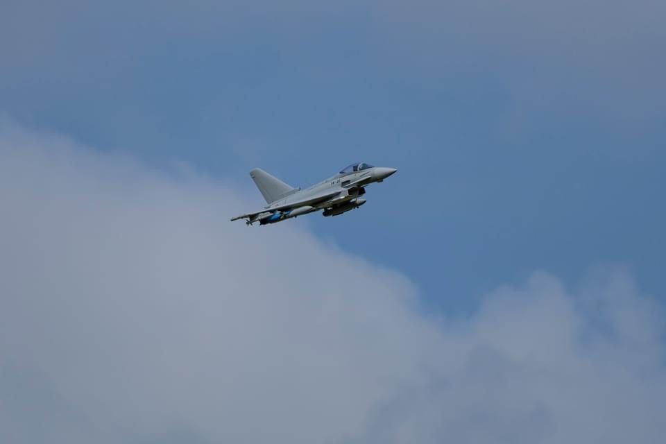
Nice cloud in background.

Zoom to the moon to check max roll rates.
Some Happy Snaps before engine start.
Was a perfect day for test flight.
Should have waited for another hour and the runway grass was mowed. But we bumped on out and took off.
My friend Gary had his super camera out today and got the video and these inflight photos.
Good shot of all the under wing bling.
Nice cloud in background.
Zoom to the moon to check max roll rates.
 05-12-2023, 03:31 PM
#53
Great work Gary! It looks almost real, especially from underneath. Glad that you fixed the slipping starter, but a bit of a worry regarding the fuel leak, did you manage to fix that?
05-12-2023, 04:05 PM
#54
Thread Starter
My Feedback: (20)
First Flight Report
The plan was to fly in high rate pitch and low rate roll. This was a bad idea as nothing near high rate was needed with the CG at 30mm behind the factory marks. The rapid left roll on take off was probably me over controlling pitch at rotation and a bumpy runway because of high grass. The jet rotated much faster than I expected and dropped the left wing. Some how I recovered. Trim was not off very much as only a couple of clicks of right trim were needed for wings level hands off...But, it scared me so much that I forgot to switch to low rate pitch and this caused overcontrol in pitch during the rest of the flight. Next time will be low rate and I expect it will be fine.
After some small pitch and roll trim inputs I turned the gyro on and the jet was much more stable and had a more solid feel. I started dialing up the gyro gain and after just two clicks on the knob I got some gyro oscillation so I went back to the initial settings.
At about half fuel remaining I did an inflight CG check by pitching up 45 degrees and rolling inverted. This showed it to be slightly nose heavy. I could tell the nose would tend to drop in turns especially at lower speeds. I will remove the 1.25 oz of lead in the nose before the next flight.
After dropping the gear I continued to over control pitch and thought of adding more expo but mostly the problem is too much pitch rate. Therefore just switching to low rate will make a big difference. It was easy to land as long as I didn't mess too much with the stick in the flare as I learned on the first landing attempt. On the second approach I concentrated on very small pitch inputs and it was much better. Again low rate would have been the answer. In the flare I did not reduce thrust to idle till after touchdown because the delta wing and all the drag from the external stores really slowed it down quickly.
Now the bad news...My turbine failed to cool down after shutdown again. The motor ran but was slipping again on the O ring. The RPM was zero and I could not get it the rotor turn even when the motor was running. I will inspect it later but will probably put the turbine from my MIg-29 in it while I figure it out. As a result of this I only got one flight today.
Over all I'm very happy with it. The fuel tanks worked great inflight but I learned I have to make sure all the air is out of both tanks during fueling because of the shape of the tank design and where I put the vents in the tanks. This is easily done by tilting the jet slightly nose down and left roll followed by nose up and right roll. It was easy to do in the table and I will explain more later. I really love the fuel sight gage in the nose gear well and after about 5 minutes I still had abut 1/2 in the forward tank. I look forward to flying again with less nose weight and lower pitch rates. It will be a keeper for sure.
Gary
05-12-2023, 04:08 PM
#55
05-13-2023, 04:02 PM
#56
Thread Starter
My Feedback: (20)
FOD on turbine screen

Today I opened the turbine hatch to replace the X-45 with another one from my Mig-29. I was surprised to see several pieces of grass stuck on the FOD screen. I have had this issue before on several jets and have always found the problem is the nose wheel is kicking up grass into the nose gear well and then it finds a path to the turbine. Well sure enough I found an open path from the nose gear well straight back to the turbine.
The gap between the tank and the gear well is 3-5 mm wide. I blew compressed air in the gear well and could feel a good flow in the turbine bay. I'm sure this is where the grass came in. I've rarely seen grass be sucked in the inlet that is in front of the nose wheel.

I cut a strip of 1/4" foam to stuff in the openings.

I stuffed the foam in the gaps. I also put a small piece of foam in the gear strut slot and let it get pushed back out of site when the gear was retracted to seal up the strut slot opening. I think this will stop most of the grass from getting to the turbine.
Today I opened the turbine hatch to replace the X-45 with another one from my Mig-29. I was surprised to see several pieces of grass stuck on the FOD screen. I have had this issue before on several jets and have always found the problem is the nose wheel is kicking up grass into the nose gear well and then it finds a path to the turbine. Well sure enough I found an open path from the nose gear well straight back to the turbine.
The gap between the tank and the gear well is 3-5 mm wide. I blew compressed air in the gear well and could feel a good flow in the turbine bay. I'm sure this is where the grass came in. I've rarely seen grass be sucked in the inlet that is in front of the nose wheel.
I cut a strip of 1/4" foam to stuff in the openings.
I stuffed the foam in the gaps. I also put a small piece of foam in the gear strut slot and let it get pushed back out of site when the gear was retracted to seal up the strut slot opening. I think this will stop most of the grass from getting to the turbine.
05-17-2023, 09:58 AM
#57
Thread Starter
My Feedback: (20)
Five successful flights today!
Had a great time today with the Eurofighter. Made 5 flights. X-45 turbine was flawless. Most of the flight time was dialing in trim, adjusting control rates and expo, gyro rates, canard rates. We have the jet working well. I find with all the stores on the wing and the delta wing it slows down rapidly on final approach and will drop in if you reduce thrust too fast. My best landings were rolling out of the final turn with an acceptable descent rate and then not pulling off the thrust until after the round out, flare, and touchdown.
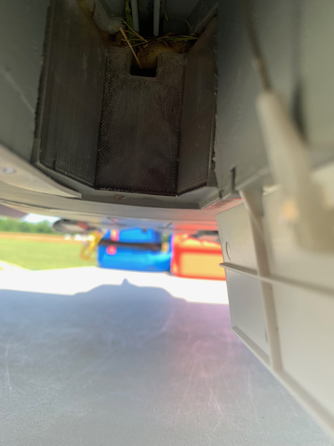
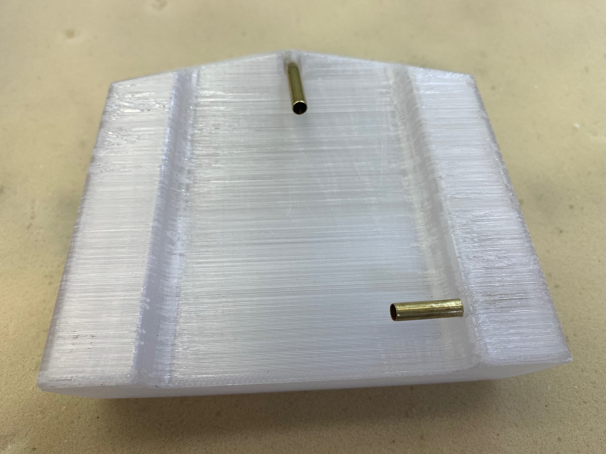
This is the front wall of the main tank viewed from the nose wheel well looking aft. I took the photo in the blind because of the bright sun but you can see the faint line of the fuel level showing the front tank still about half full. This was after a 6 min flight. I increased my time to 7 minutes and still had fuel on later flights. Depending on thrust management you could probably get 8 minutes. You can also see grass stopped by the foam packing that did not get to the turbine.
After today I can say that the fuel tanks and plumbing have been validated. The turbine install is working good. As for flying the jet it's all up to how you set it up. I'm flying in low rate roll, low rate pitch with 40% expo, canard rates have been reduced to 15% in pitch, canard trailing edge droop works well for tank off, high alpha, and landing. I took out the 1.25 oz of nose weight and the CG is better and the jet does not drop the nose in turns as bad. It will probably get adjusted aft some more as I get more fights.
Its a fun jet, enjoy the conversion if you try one!
Had a great time today with the Eurofighter. Made 5 flights. X-45 turbine was flawless. Most of the flight time was dialing in trim, adjusting control rates and expo, gyro rates, canard rates. We have the jet working well. I find with all the stores on the wing and the delta wing it slows down rapidly on final approach and will drop in if you reduce thrust too fast. My best landings were rolling out of the final turn with an acceptable descent rate and then not pulling off the thrust until after the round out, flare, and touchdown.
This is the front wall of the main tank viewed from the nose wheel well looking aft. I took the photo in the blind because of the bright sun but you can see the faint line of the fuel level showing the front tank still about half full. This was after a 6 min flight. I increased my time to 7 minutes and still had fuel on later flights. Depending on thrust management you could probably get 8 minutes. You can also see grass stopped by the foam packing that did not get to the turbine.
After today I can say that the fuel tanks and plumbing have been validated. The turbine install is working good. As for flying the jet it's all up to how you set it up. I'm flying in low rate roll, low rate pitch with 40% expo, canard rates have been reduced to 15% in pitch, canard trailing edge droop works well for tank off, high alpha, and landing. I took out the 1.25 oz of nose weight and the CG is better and the jet does not drop the nose in turns as bad. It will probably get adjusted aft some more as I get more fights.
Its a fun jet, enjoy the conversion if you try one!
Last edited by Viper1GJ; 05-17-2023 at 01:09 PM.
The following users liked this post:
Aussie1 (05-17-2023)
05-17-2023, 01:04 PM
#58
Thread Starter
My Feedback: (20)
Removing trapped air from the tanks during fueling.
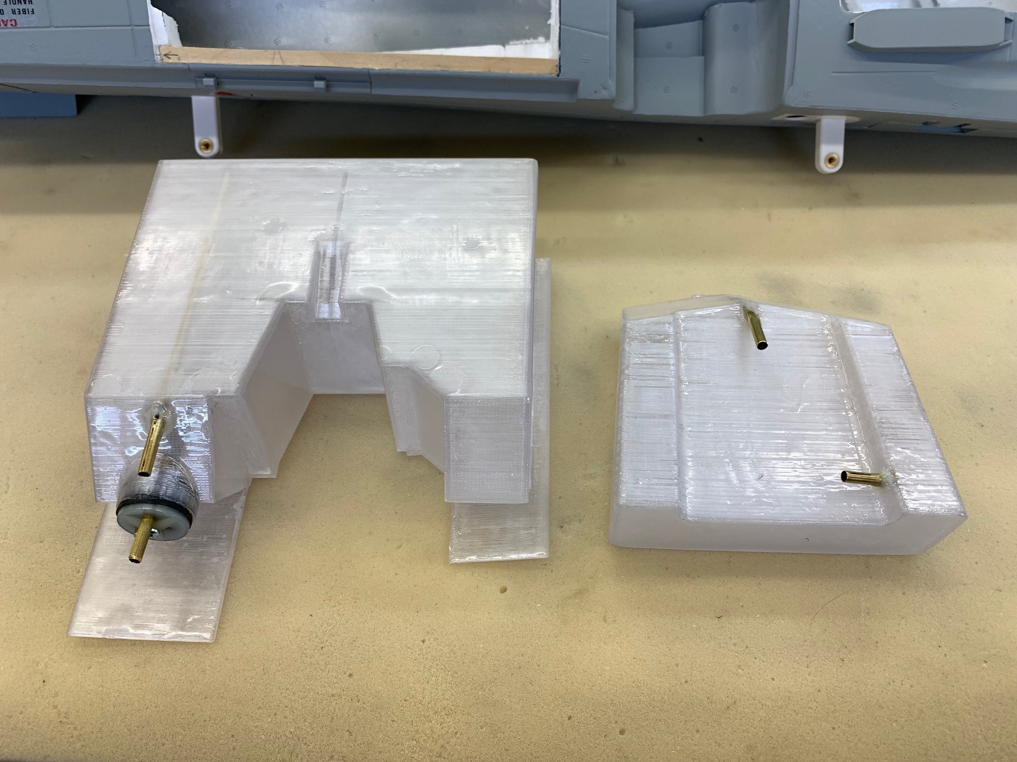
I now have 6 flights on the jet and the fuel system is working perfectly and I'm very happy with the tanks. The small CG shift during burnout is not noticeable and is insignificant. Keith did a great job with the CAD design.
The tanks do have one issue because of their design to get max volume in the space available. The issue is it is possible to trap some air in both tanks during normal refueling when sitting on the gear. The main tank can trap some air in the left and right forward sections depending on the sitting attitude. The rear tank will always trap air in the left and right sections that are raised over the main body of the tank.
It is easy to remove the air during fueling. I fill the tanks normally using a lower pressure with a variable speed pump. I always connect the vent out the bottom jet to overflow back into the jug. After the rear tank is full and the vent tube is overflowing back into the jug I slow the pump to very slow speed so as not to over pressurize the tanks.
Then I lift the tail slightly and roll the jet to the left to raise the vent tube in the right rear of the main tank and allow any air to go out of the main tank vent and into the rear tank. With the tail slightly raised and left wing still low any air trapped in the right side of the rear tank will flow to the back of the rear tank. I then roll the right wing low and then lower the tail and slightly raise the nose. This allows the air bubble to flow forward to the vent tube and exit out the tank. I will see air flowing back into the jug in the vent return line. Once there is a solid stream of fuel flowing back into the jug both tanks are full with no air. A few extra steps but no big deal with a foamy jet. Or you can just fly with a little less fuel as there is plenty.
If I had it to do over again....I would place the vent tube in the rear tank on the right side. This would change nothing about how the system would work but it would eliminate the need lower the right wing after you raise the nose since the aft tank bubble would already be on the right side where the vent tube would be. It's still no big deal and maybe only gets you that last 1 or 2 oz but it works.
Last edited by Viper1GJ; 05-17-2023 at 01:06 PM.
The following users liked this post:
Aussie1 (05-17-2023)
06-03-2023, 05:34 PM
#59
Thread Starter
My Feedback: (20)
Five more flights today.
I flew 5 more flights today on the Eurofighter. I have now moved the CG back forward to 25mm aft of the marks on the wings and it is much more pitch stable on final and easier to land. I was between 30-35mm aft of the marks before and it was just too hard for me to make a stable nose high approach at high AOA. The nose tended to rise and stay there bleeding speed. Now the pitch is more stable and much easier to make a stable approach and landing. I still carry power to the ground and reduce to idle after on the ground.
Working to get the best gyro settings in roll and yaw next to eliminate wing rocking. I made adjustments before by increasing yaw gain but a self inflicted programming error with the Jeti Assist gyro caused the yaw output to be zero with resulting wing rock again when the CG was still aft. I also removed all the stores when moving the CG forward and it reduced the wing rock a little especially at slow speed high AOA.
I've fixed the yaw gain programming error and look forward to getting it dialed in the next time out as it is a fun and cool looking jet to fly.
I really like it.
Gary
Last edited by Viper1GJ; 06-03-2023 at 05:55 PM.
The following users liked this post:
Afterburners (06-03-2023)
06-04-2023, 04:12 PM
#61
Thread Starter
My Feedback: (20)
Maintenance check after the last five sorties
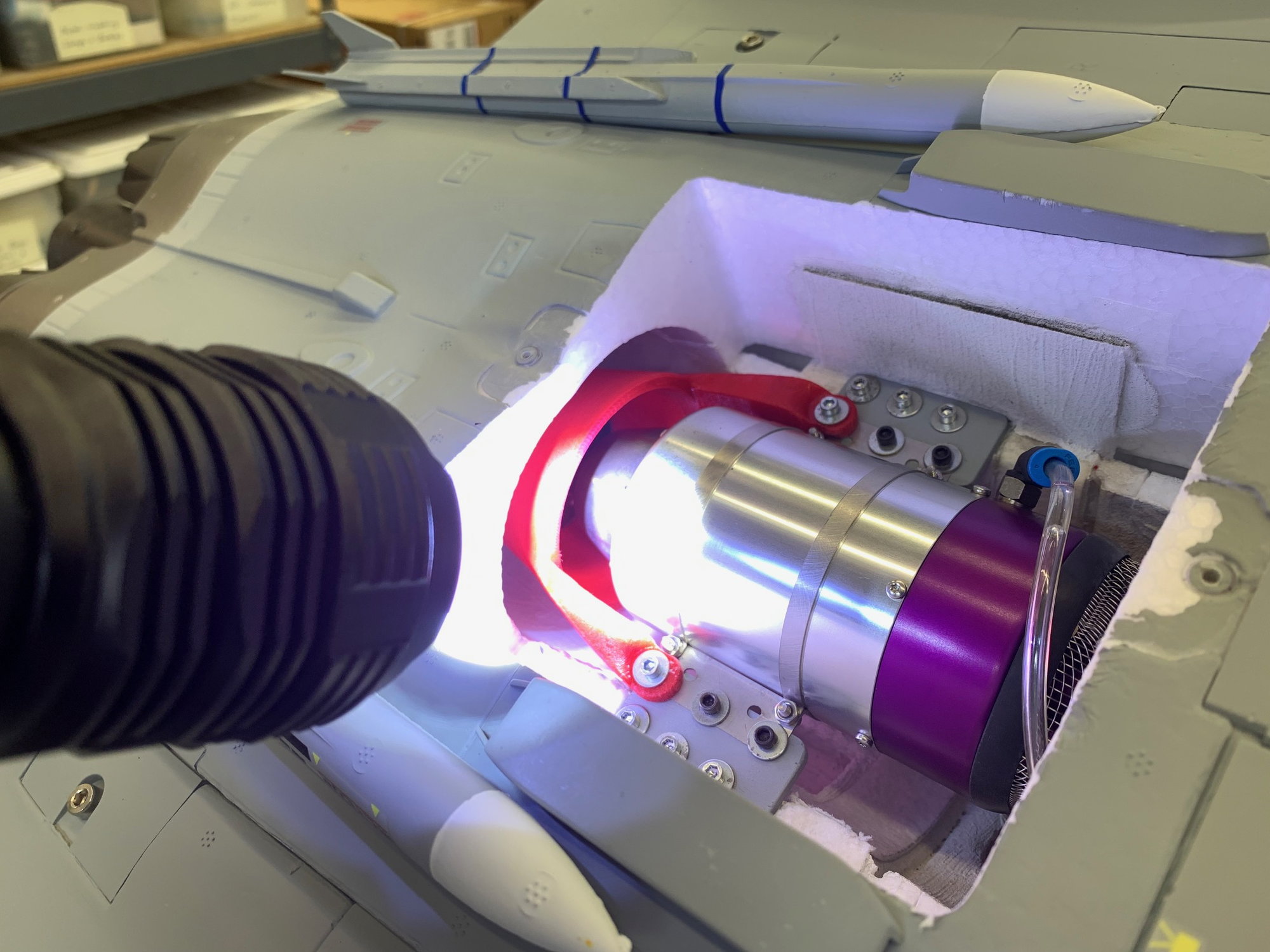
I opened up the turbine hatch and inspected for any heat damage or loose screws. So far after 12 flights the foam and pipe bell mouth are holding up well and shows no signs of damage in the hot areas or pipe areas. The air cooling is working well.
I did find some grass that was only at the bottom of the FOD screen. I think there was still a small hole for grass passage over the top of the main tank in the nose wheel. I stuffed a bigger piece of foam in the slot where the nose gear trunnion slides above the tank and taped over the sides inside the nose gear well. Hopefully this will seal off the path for grass to the turbine from the nose gear well.
06-04-2023, 04:34 PM
#62
Thread Starter
My Feedback: (20)
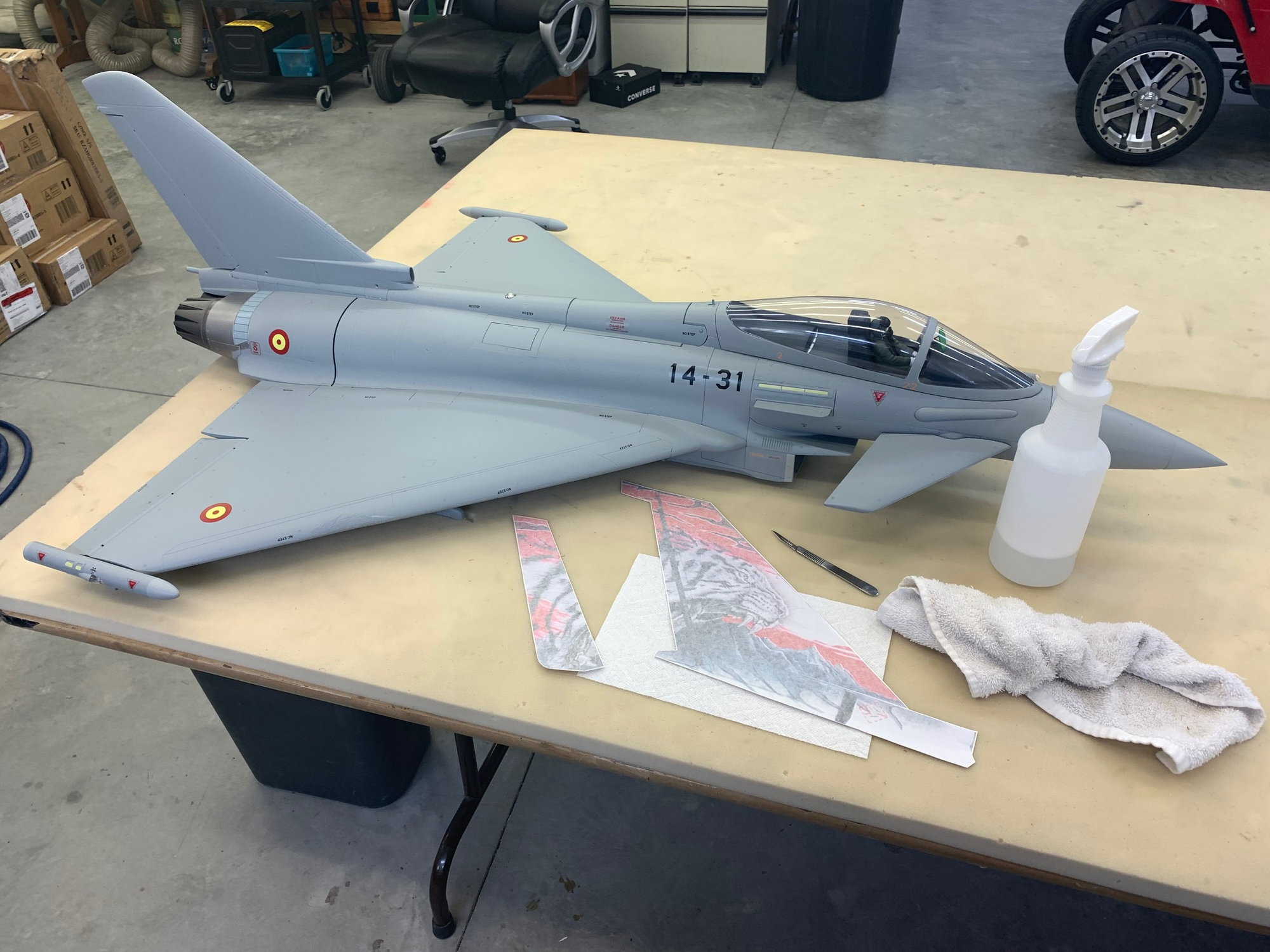
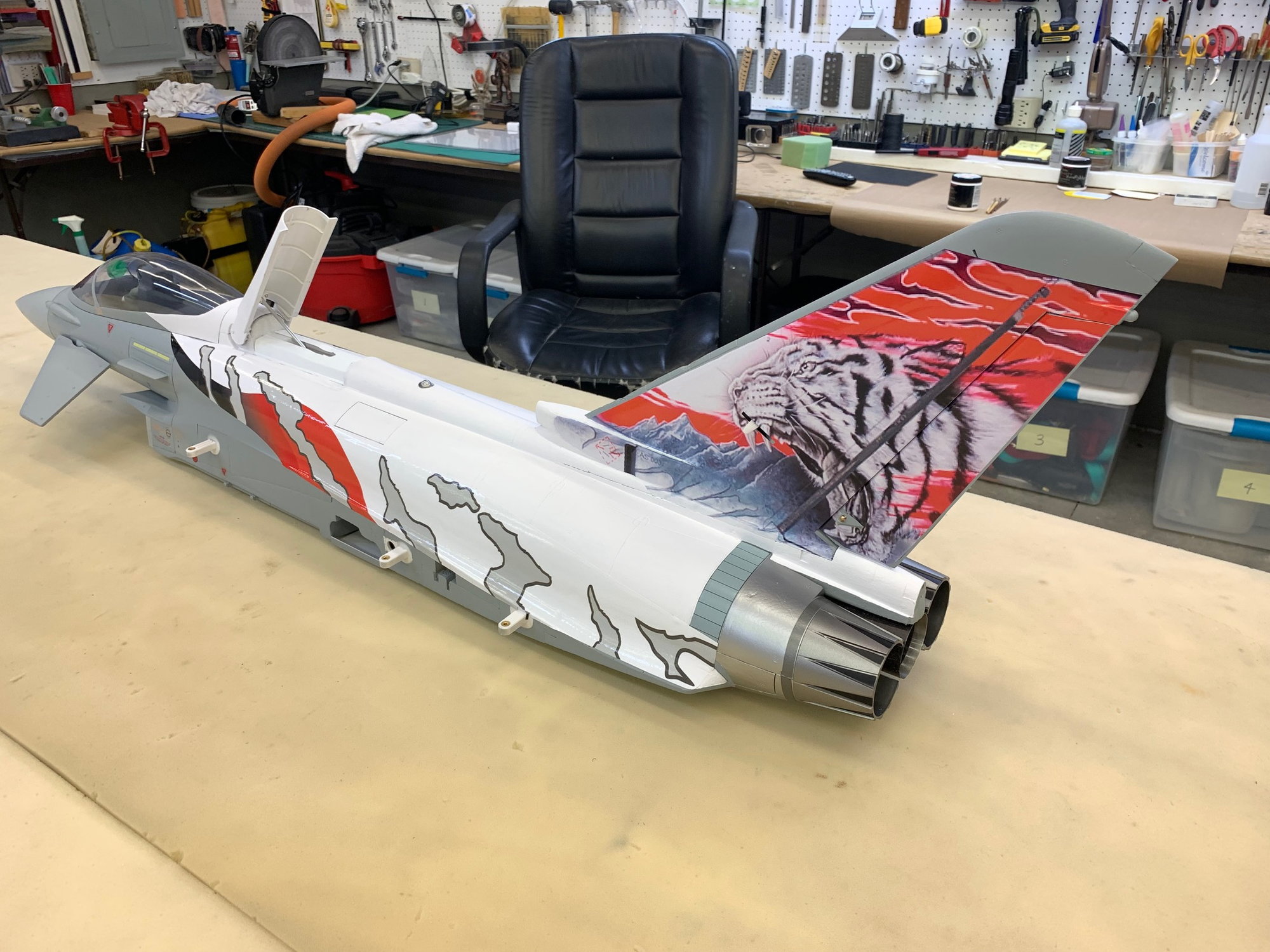
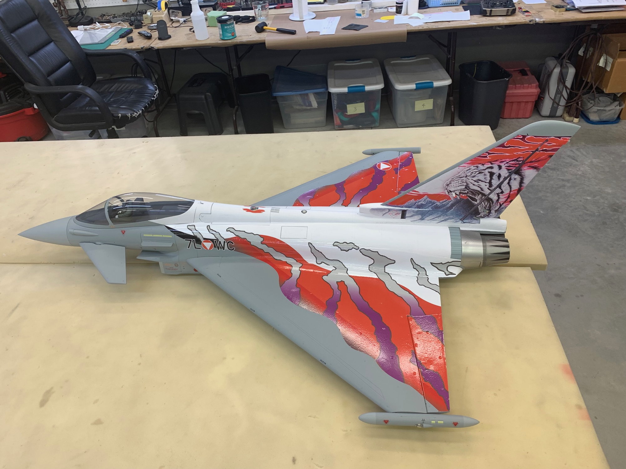
Work started today to transform the plain grey jet to the Austrian Tiger Scheme


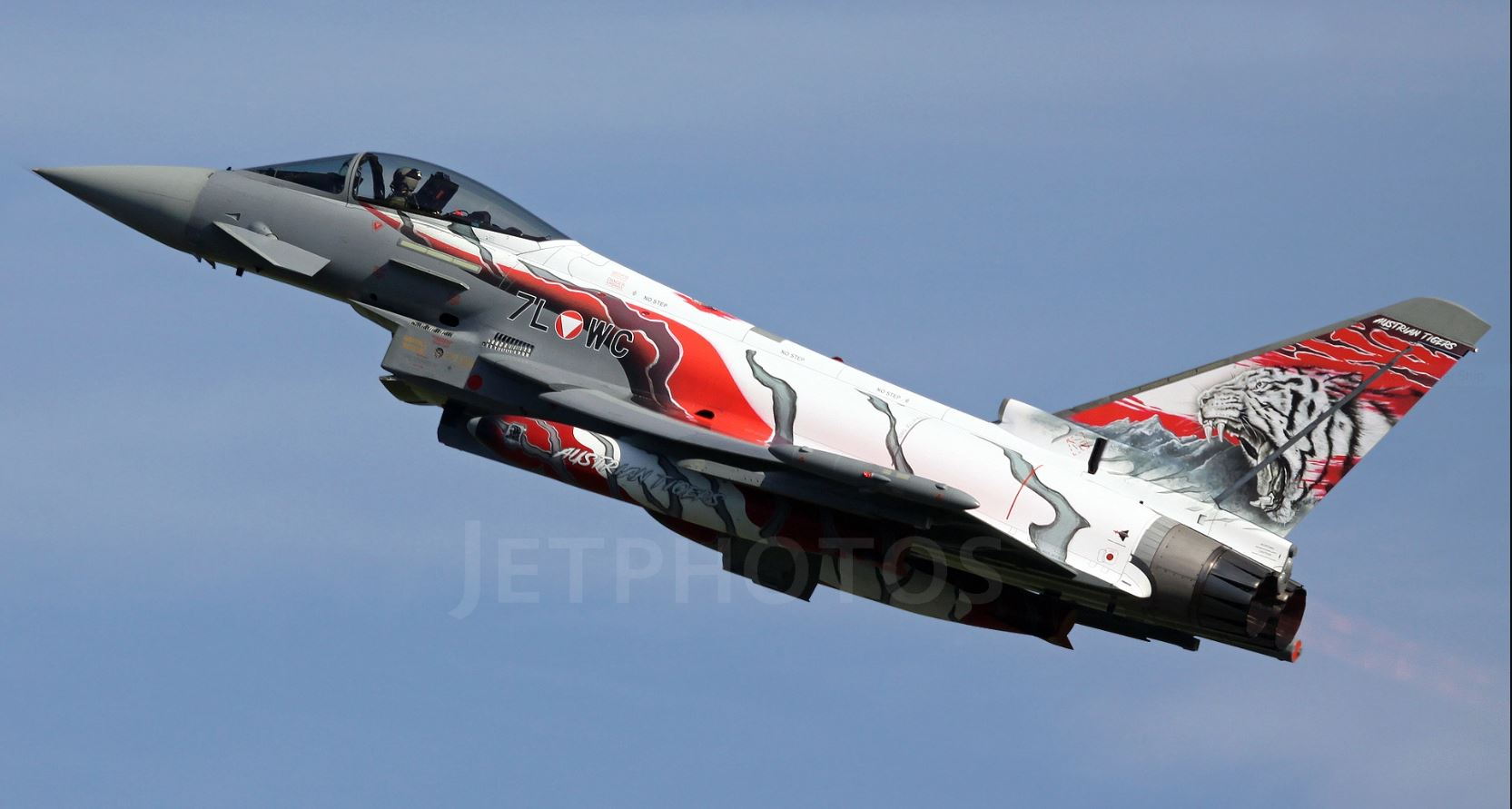


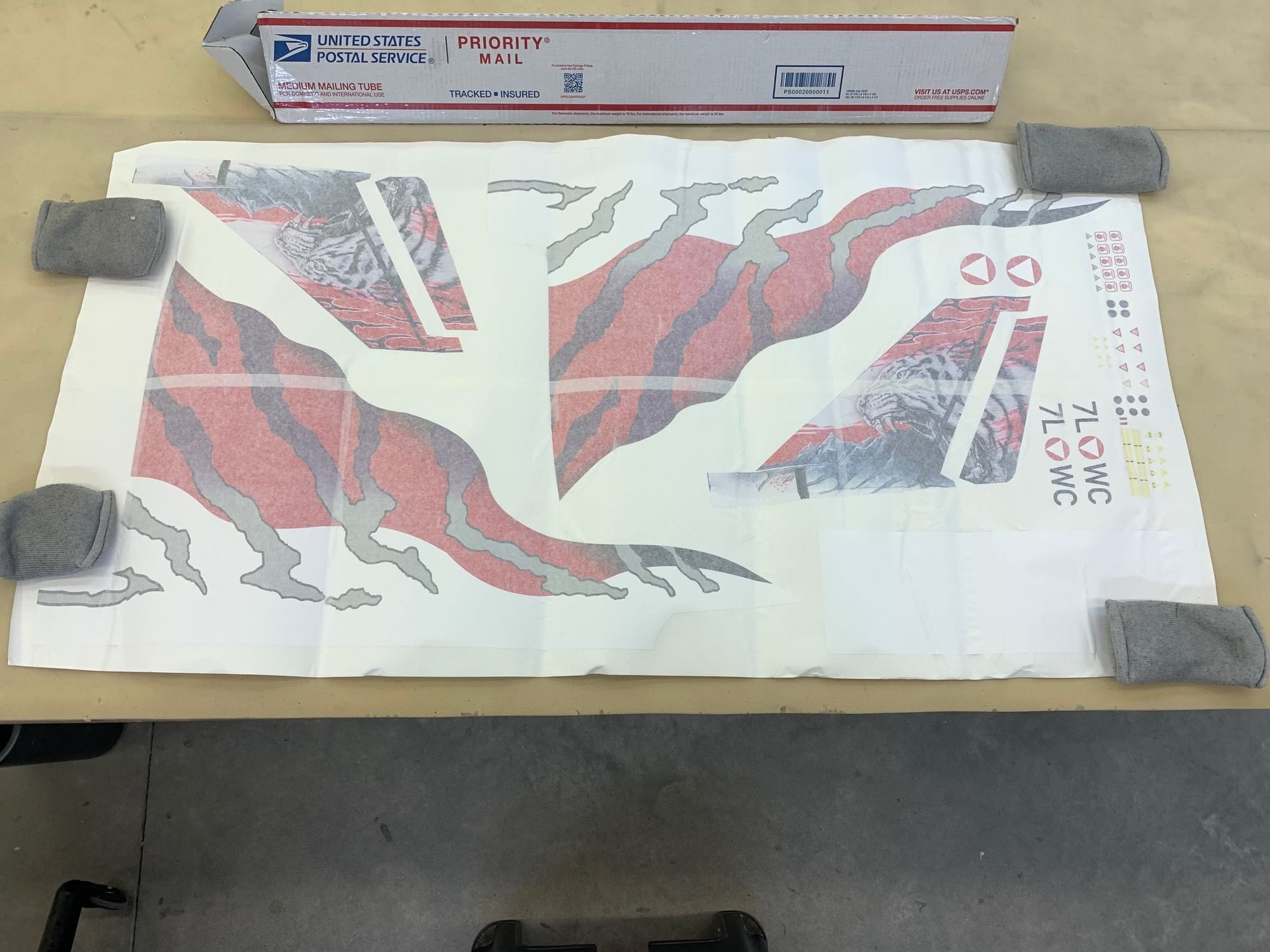
Callie Graphics for the Tiger Scheme were selected because it gives some great color contrast between top and bottom, does not require anything on the bottom, and does not require a total repaint.
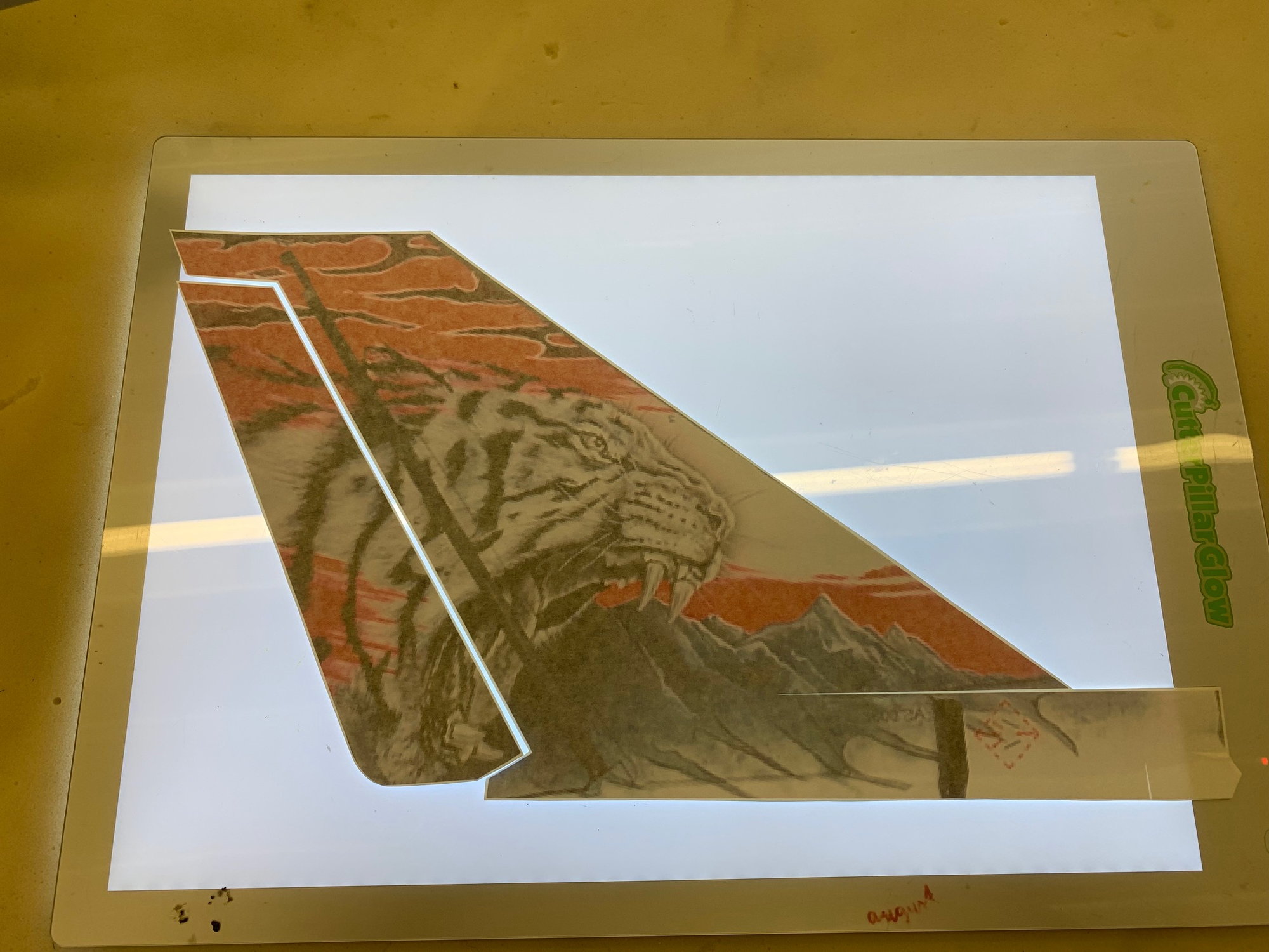
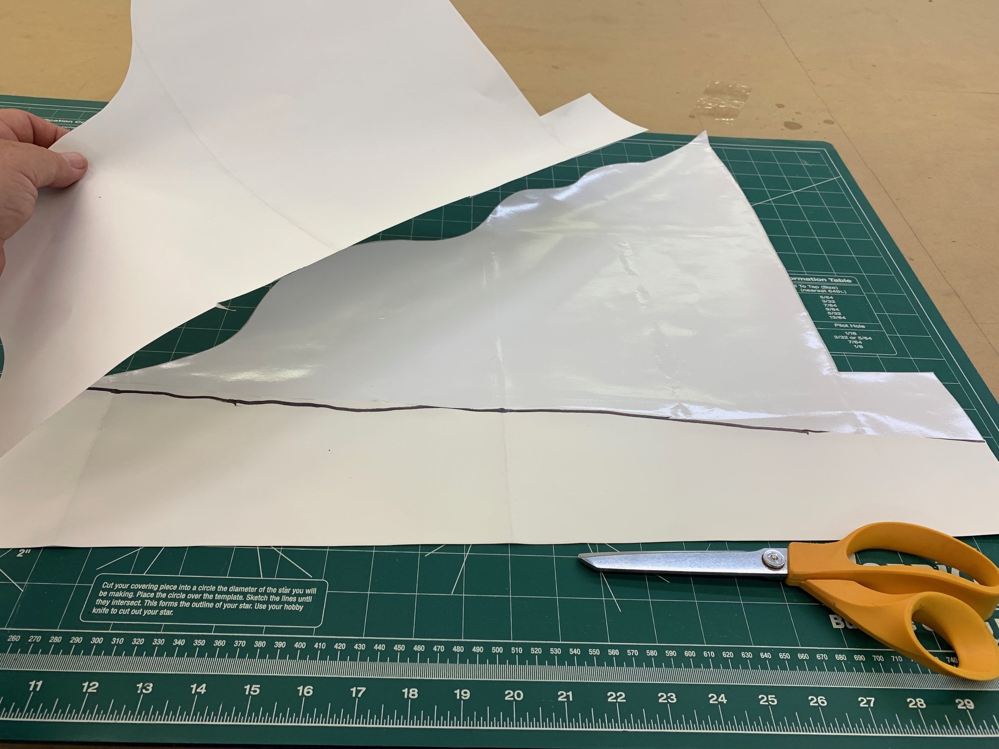
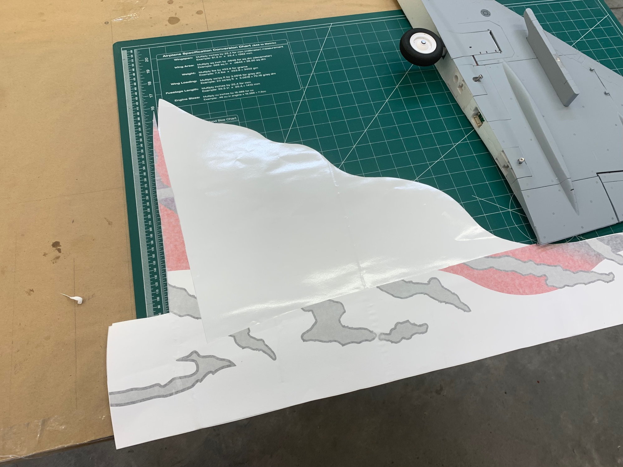
I stole my wife's light board to make it easy to cut around the vinyl prints.
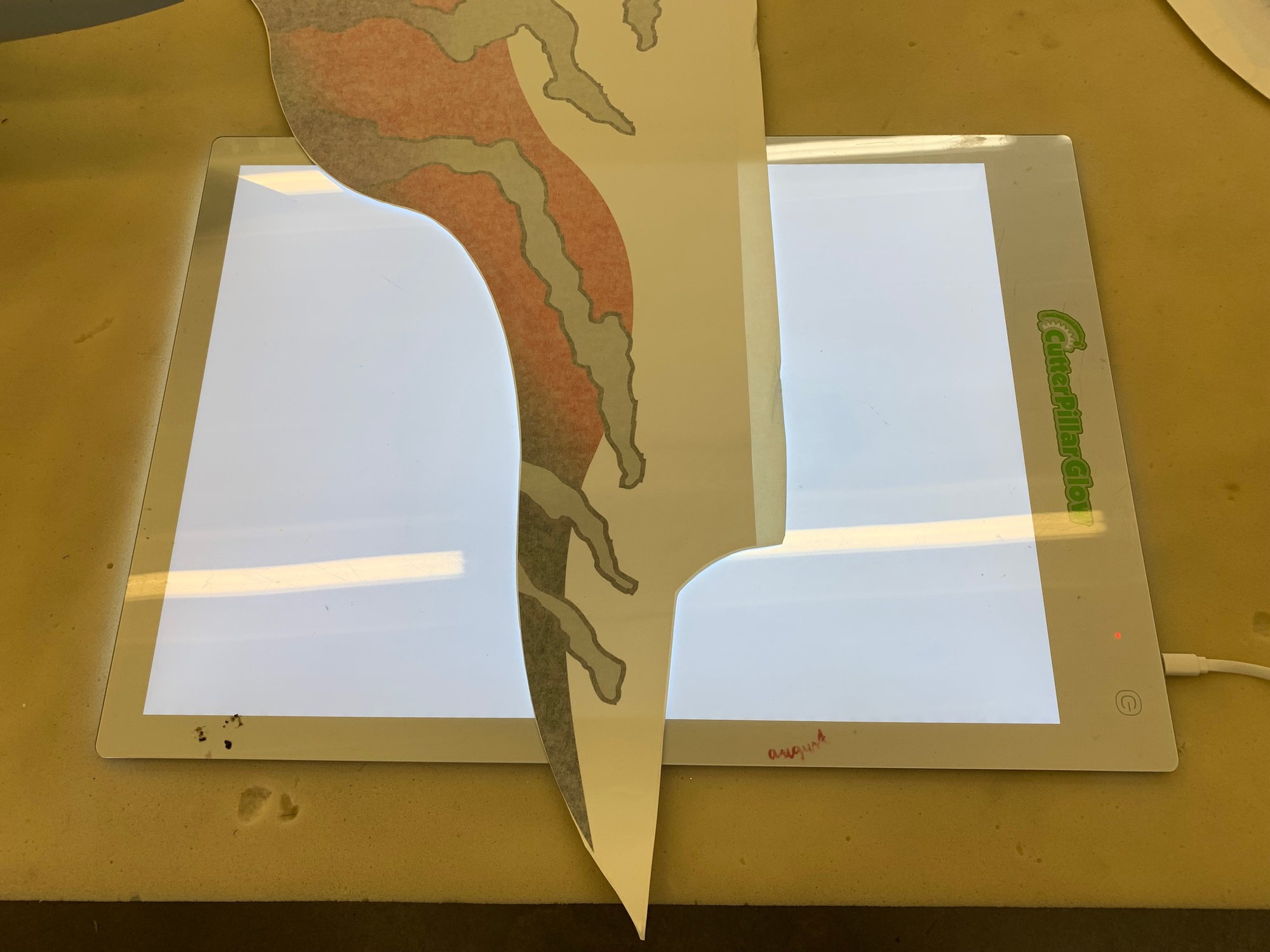
The back light made it easy to see the edges where the vinyl was white and almost invisible between the backing paper and transfer paper. I cut around the vinyl prints leaving 1-2mm over the edge. This will make it easier to place the large pieces since they are not a perfect fit.
Callie Graphics for the Tiger Scheme were selected because it gives some great color contrast between top and bottom, does not require anything on the bottom, and does not require a total repaint.
I stole my wife's light board to make it easy to cut around the vinyl prints.
The back light made it easy to see the edges where the vinyl was white and almost invisible between the backing paper and transfer paper. I cut around the vinyl prints leaving 1-2mm over the edge. This will make it easier to place the large pieces since they are not a perfect fit.
Last edited by Viper1GJ; 06-04-2023 at 04:44 PM.
06-05-2023, 02:26 PM
#63
Thread Starter
My Feedback: (20)
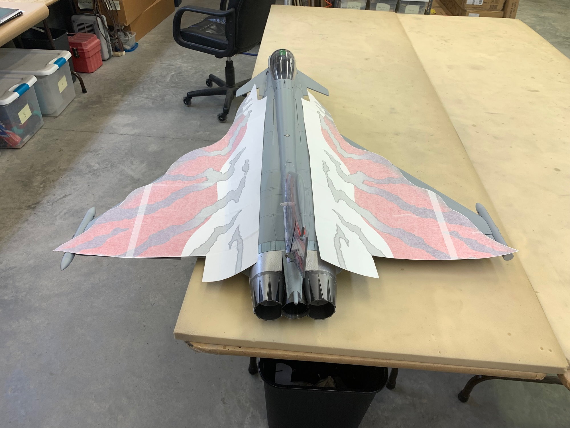
My first attempt at large vinyl graphics.
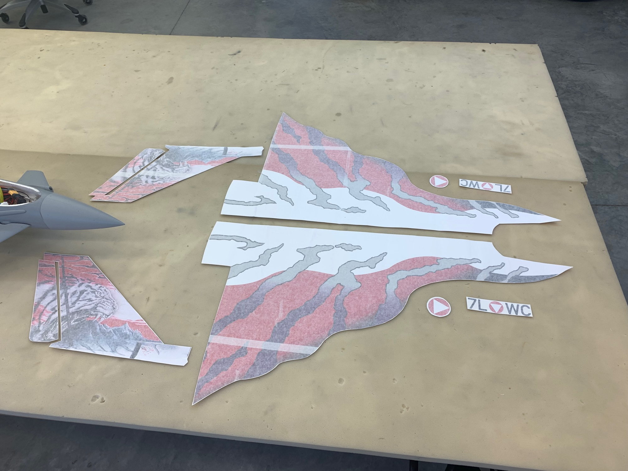
All the big pieces cut out.
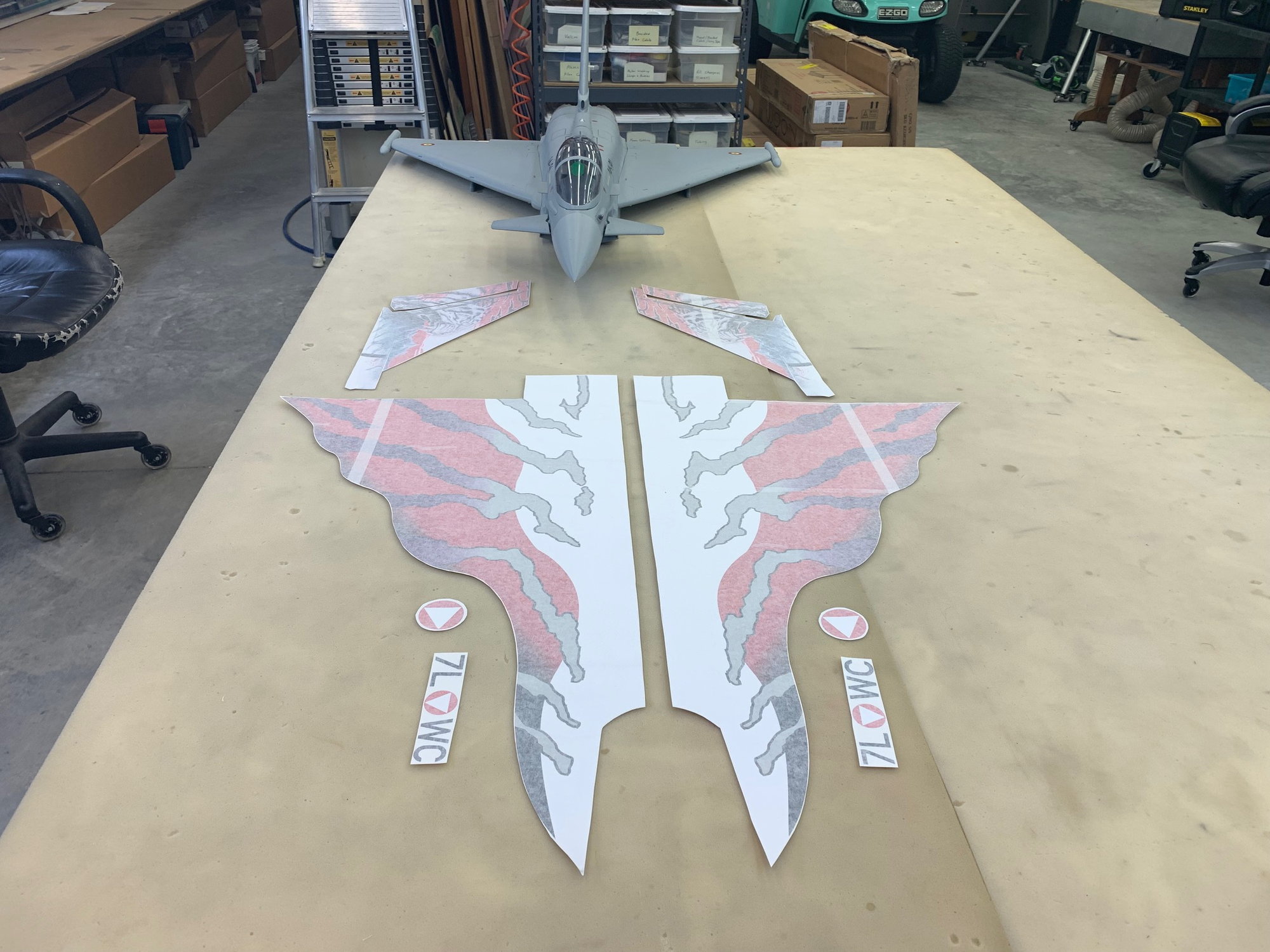
Everything still on backing paper with transfer paper on top
Soapy water spray bottle with 2 drops of dish detergent per 8oz. of water mixed, knife, paper towel, and small towel ready.

Removing backing paper from right vertical fin graphic
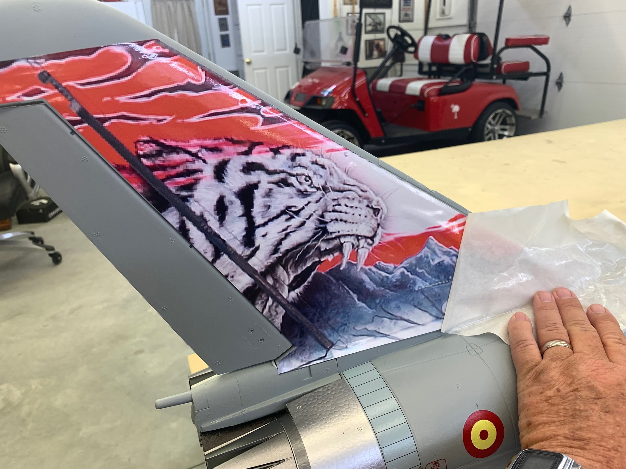
Soapy water sprayed on vertical fin and then vinyl placed after several tries to get the best fit. The graphics and the model fin are not exactly matched but close enough. Most of the water was pushed out with the yellow body putty spreader and plastic hotel key card and wiped away.
Transfer paper pulled off parallel to the surface while holding the vinyl in place with the other hand.
Transfer paper almost all off.

Rudder done the same way.
First pieces applied and smoothed out. Final trimming and painting will be sorted out after all the vinyl pieces are applied. So far so good.
All the big pieces cut out.
Everything still on backing paper with transfer paper on top
Soapy water spray bottle with 2 drops of dish detergent per 8oz. of water mixed, knife, paper towel, and small towel ready.
Removing backing paper from right vertical fin graphic
Soapy water sprayed on vertical fin and then vinyl placed after several tries to get the best fit. The graphics and the model fin are not exactly matched but close enough. Most of the water was pushed out with the yellow body putty spreader and plastic hotel key card and wiped away.
Transfer paper pulled off parallel to the surface while holding the vinyl in place with the other hand.
Transfer paper almost all off.
Rudder done the same way.
First pieces applied and smoothed out. Final trimming and painting will be sorted out after all the vinyl pieces are applied. So far so good.
The following users liked this post:
Jason3 (06-06-2023)
06-06-2023, 05:21 PM
#64
Thread Starter
My Feedback: (20)
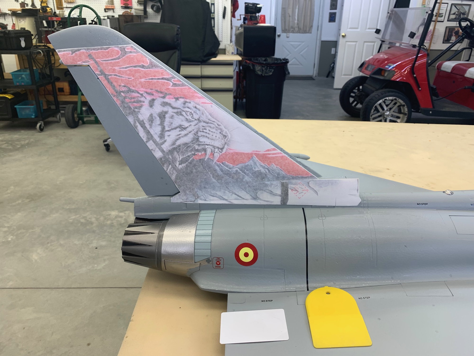
Vinyl graphics continued...
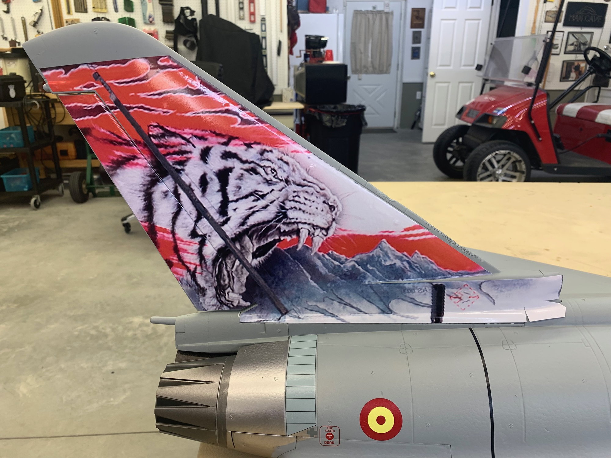
I painted over the existing markings where the vinyl will cover to avoid see through images. Some one mentioned that the graphics on the tail were pixelated and they are. This is probably because the source photo was low quality. After enlarging it looks pixelated. There are not many photos of this jet that I could find and I'm pretty sure Callie just used what was available. I did the "stand off scale" look at it today. You can see pixels at 3', barely see them at 4', and could not see them at 5'. As I explained earlier my primary desire was for good color contrast between top and bottom with the least amount of work. The graphics will work well for that.
I finished the vertical stab and rudder today. Spent most of the remaining time trying to figure out how to place the large pieces on the wing and fuse. The graphics are not exact scale and lots of compromise from full scale photos to get them placed. I think I will attempt to mark the location on both wings and place that part first. Then cut off the remaining vinyl at the wing root and then place that part on the fuse. It will be hard to get both sides to look the same plus sort out all the compound curves and angles using non shrinking vinyl. Then I will paint the center top of the fuse not covered by the vinyl white to match the white vinyl.
Suggestions welcome.
Last edited by Viper1GJ; 06-06-2023 at 05:28 PM.
 06-10-2023, 05:10 PM
#66
Thread Starter
My Feedback: (20)
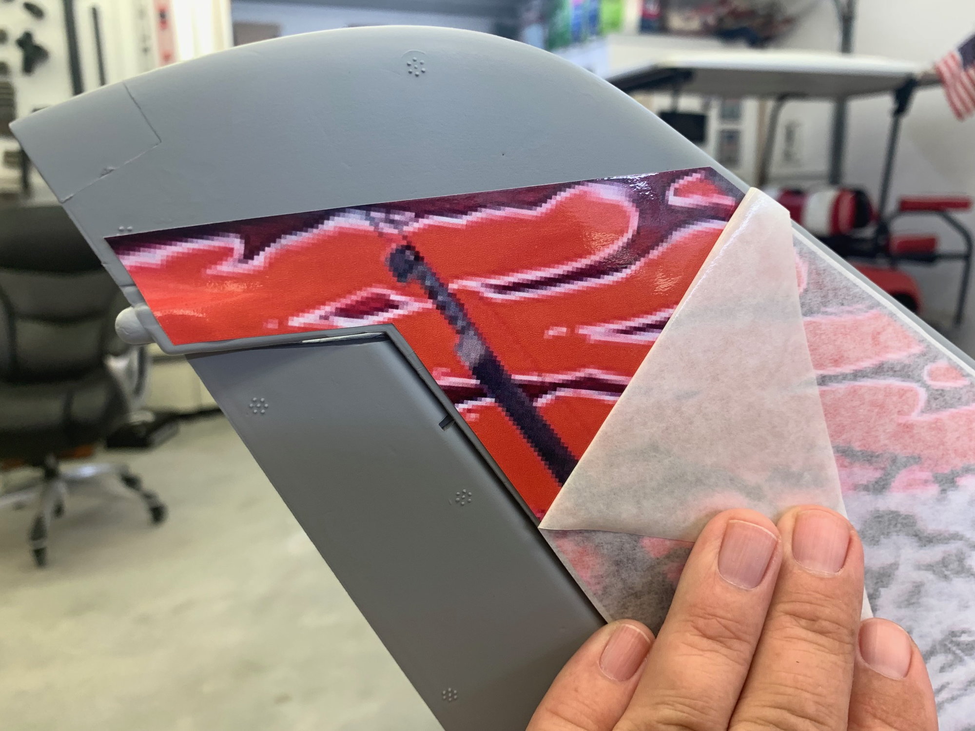
Applying Vinyl Graphics to Wings

After much looking, shifting, and comparing full scale photos I finally decided on a layout that would make the best of the graphics, the jet, and scale look. I placed index marks on the graphics to make alignment on both sides easier. The mark here is in the black outline in the middle of the vinyl and aligns to a panel on each wing.
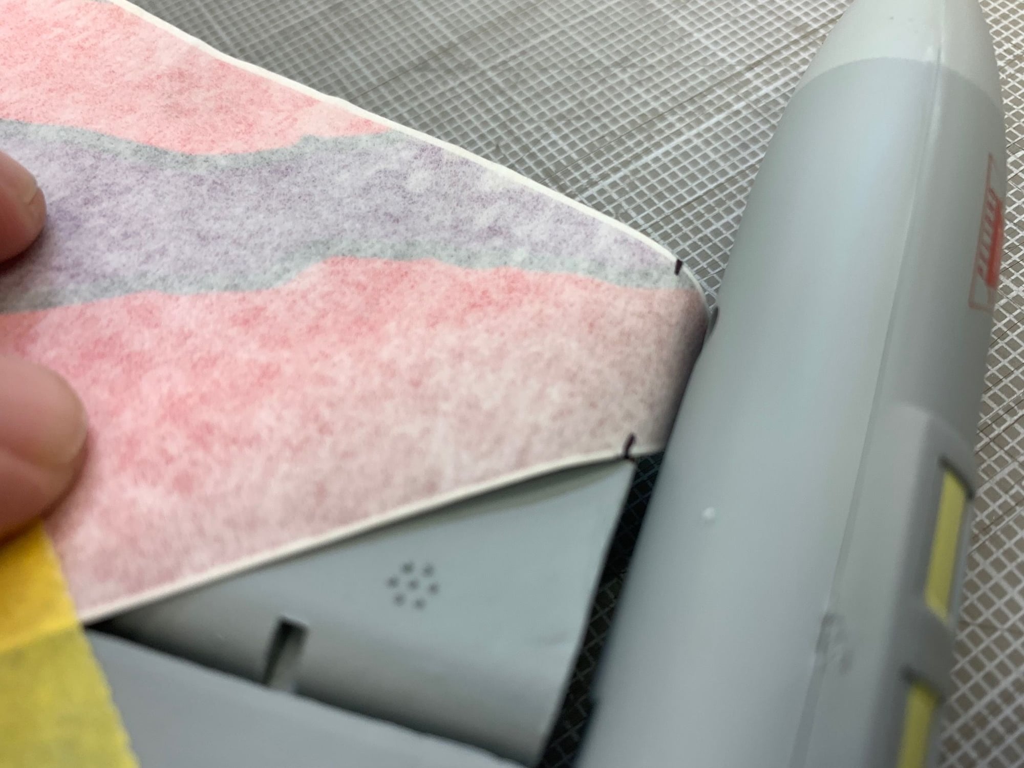
Marks at tip of elevons.
Marks and root of wing
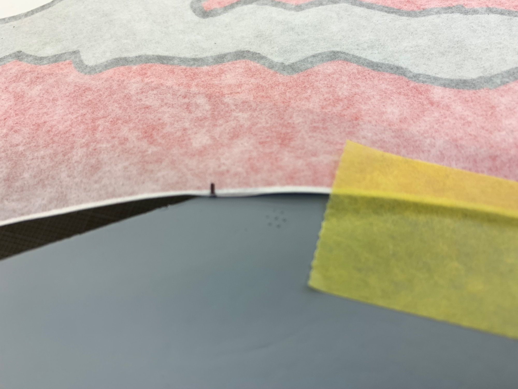
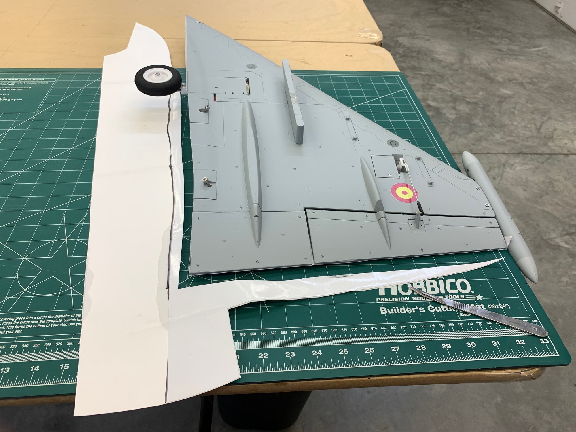
Vinyl was taped on top and wing flipped over. A marker line made about 1/2" away of root for cutting backing paper.

Backing paper removed to the line.
Backing paper cut off at the line. This will leave the backing paper on the vinyl that goes on the fuse sides later.
After much looking, shifting, and comparing full scale photos I finally decided on a layout that would make the best of the graphics, the jet, and scale look. I placed index marks on the graphics to make alignment on both sides easier. The mark here is in the black outline in the middle of the vinyl and aligns to a panel on each wing.
Marks at tip of elevons.
Marks and root of wing
Vinyl was taped on top and wing flipped over. A marker line made about 1/2" away of root for cutting backing paper.
Backing paper removed to the line.
Backing paper cut off at the line. This will leave the backing paper on the vinyl that goes on the fuse sides later.
Last edited by Viper1GJ; 06-10-2023 at 05:13 PM.
06-10-2023, 05:22 PM
#67
Thread Starter
My Feedback: (20)
Vinyl Application Continued.

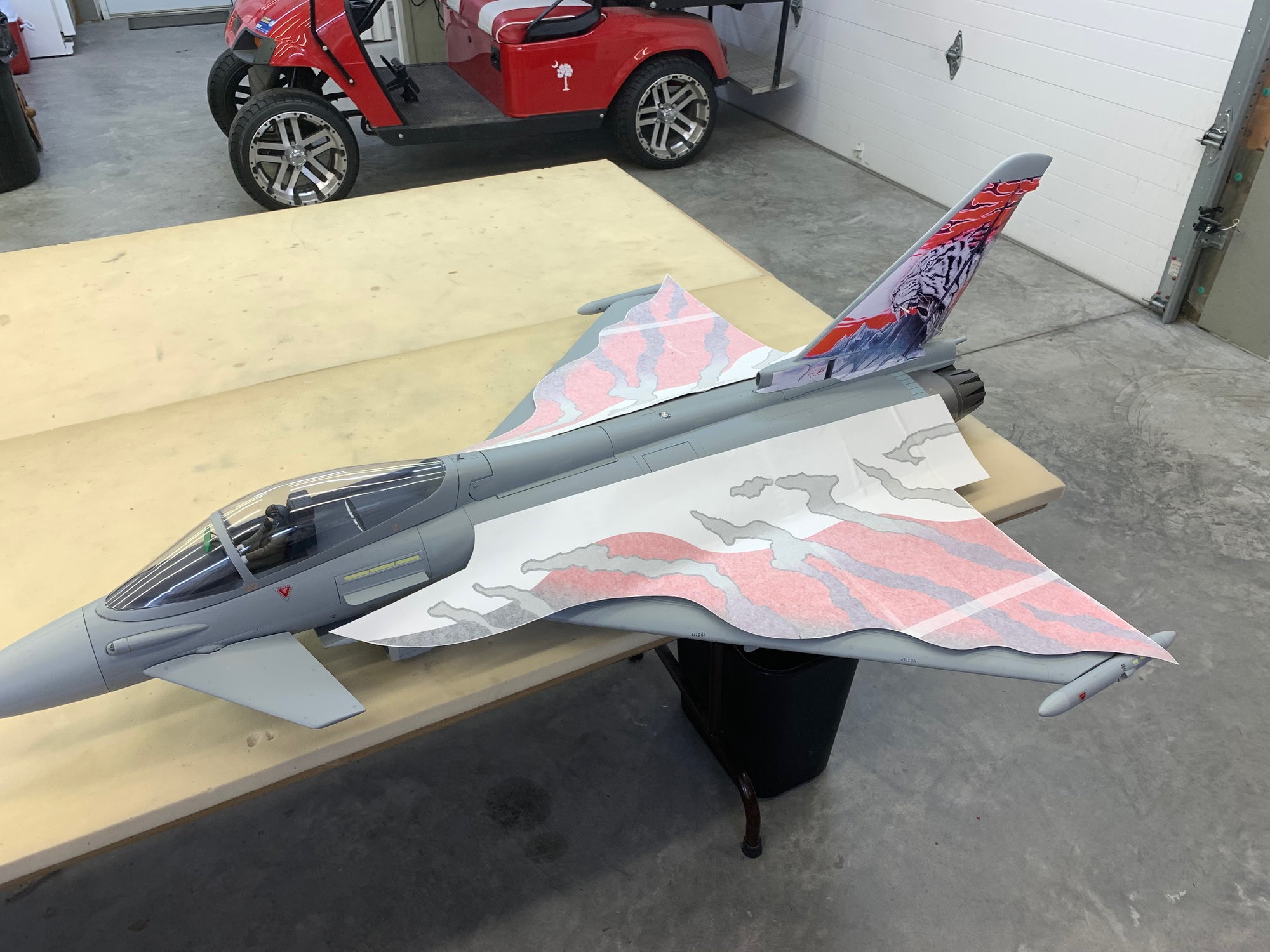
Water sprayed on wing and vinyl.
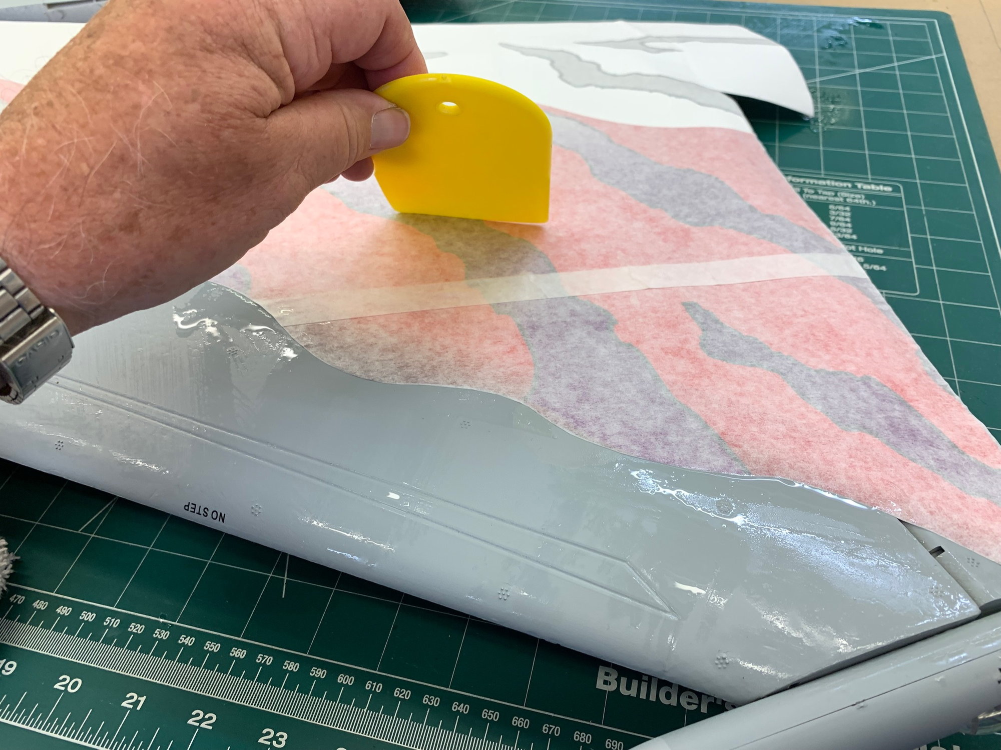
Vinyl put in place and water pushed out from under and wiped off.
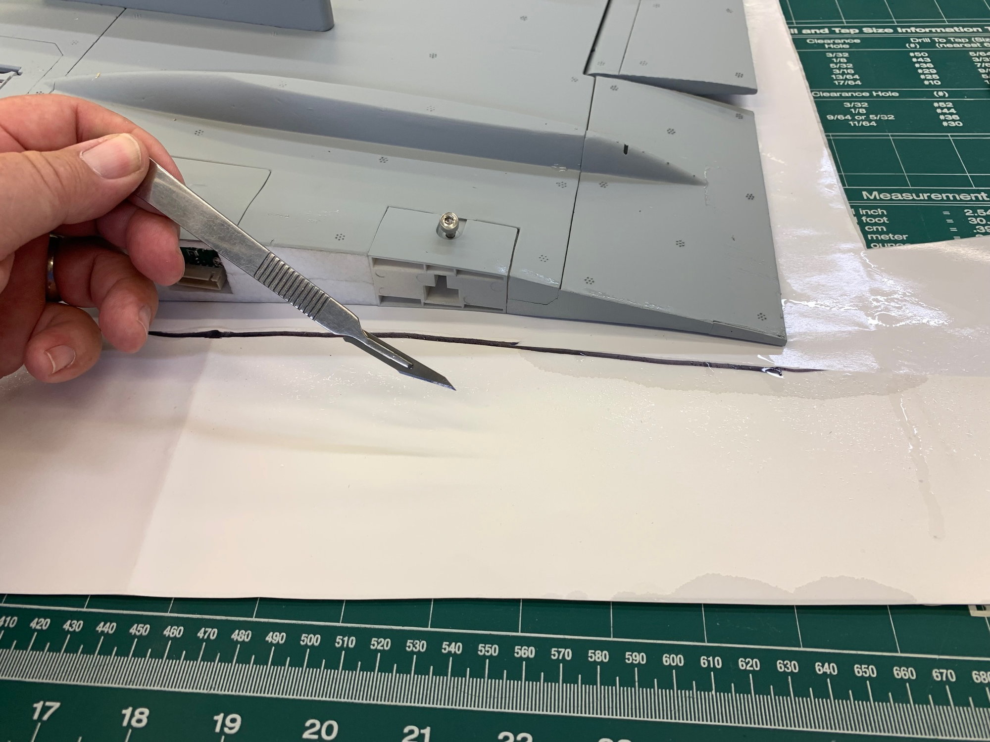
Wing flipped over on cutting mat and vinyl cut off at wing root.
WIng tip moved to edge of table to allow trailing edge to be in contact with cutting board for trailing edge cut.
Backing paper reattached to remaining vinyl to keep clean for application to fuse later.
Water sprayed on wing and vinyl.
Vinyl put in place and water pushed out from under and wiped off.
Wing flipped over on cutting mat and vinyl cut off at wing root.
WIng tip moved to edge of table to allow trailing edge to be in contact with cutting board for trailing edge cut.
Backing paper reattached to remaining vinyl to keep clean for application to fuse later.
06-10-2023, 05:30 PM
#68
Thread Starter
My Feedback: (20)
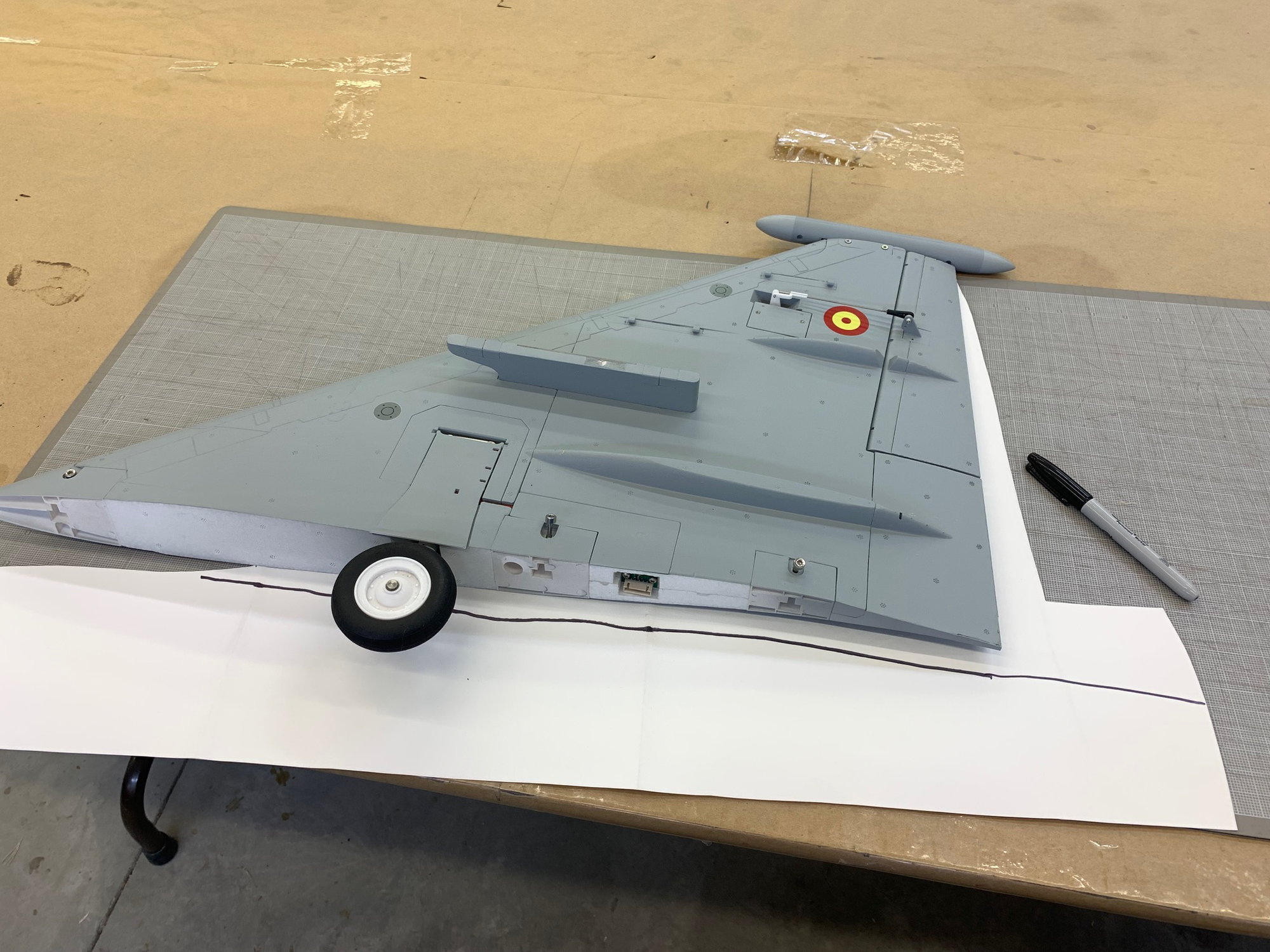
Vinyl trim cuts and smoothing.
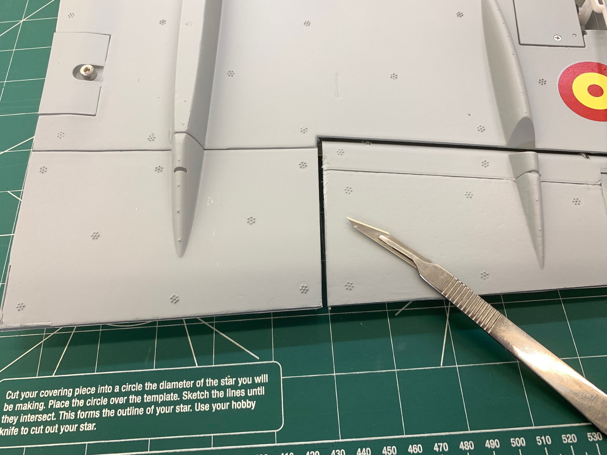
Clearance cuts between wing and elevon made from bottom with cutting board.
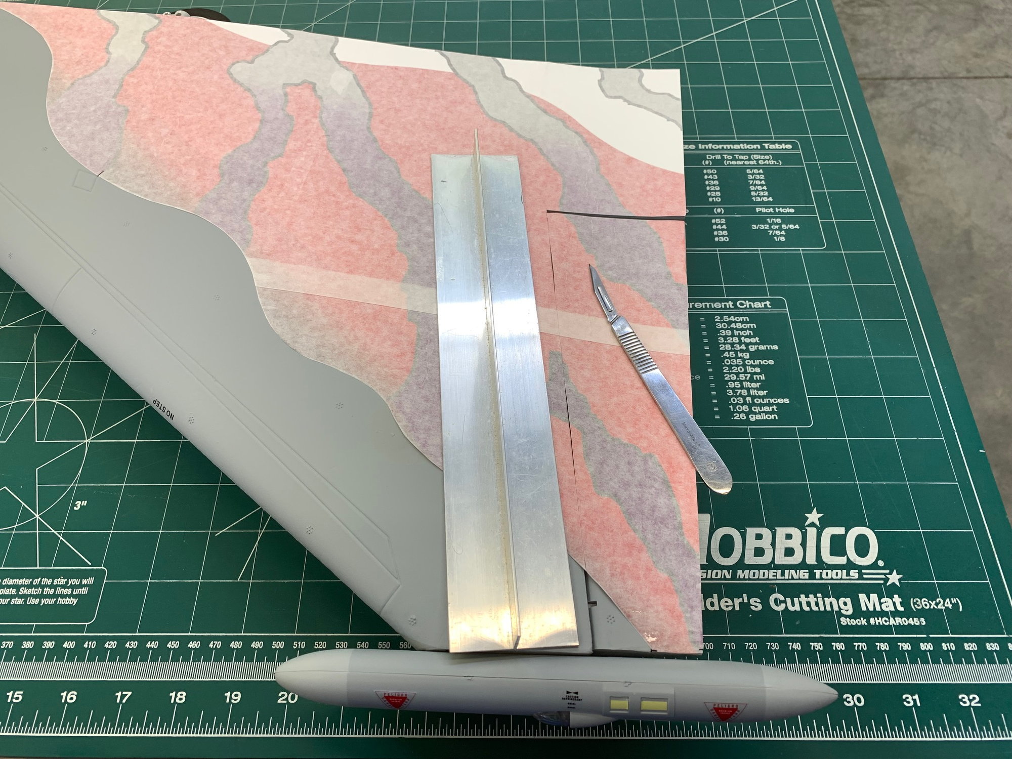
Straight edge used to make elevon hinge line cuts.
Vinyl after water squeezed out and edges rubbed down.
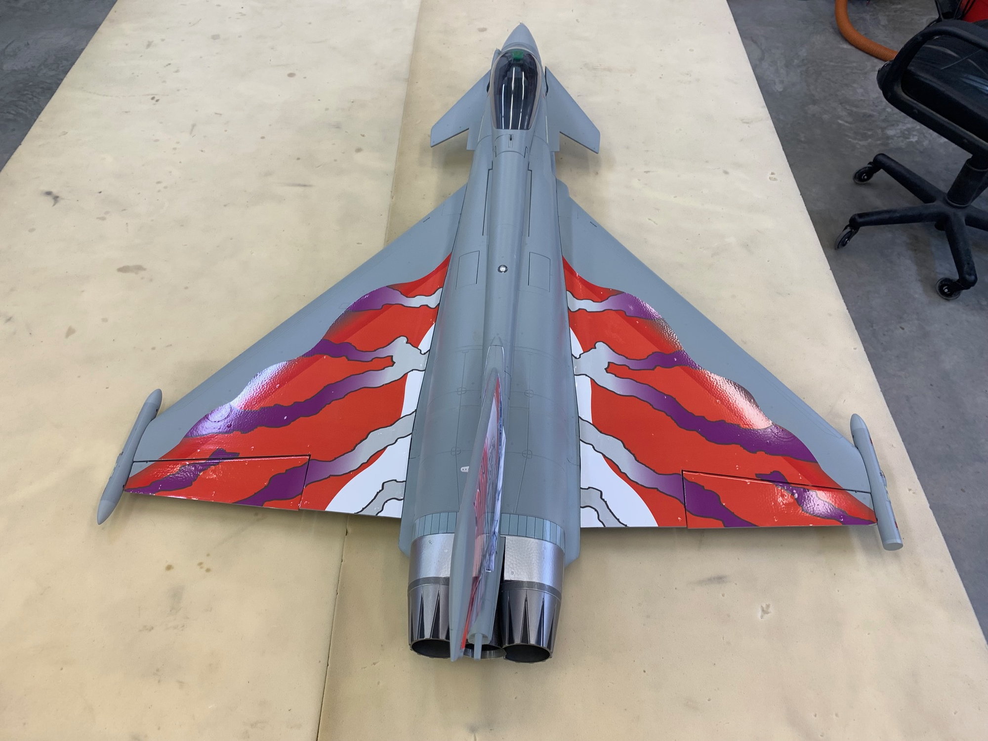
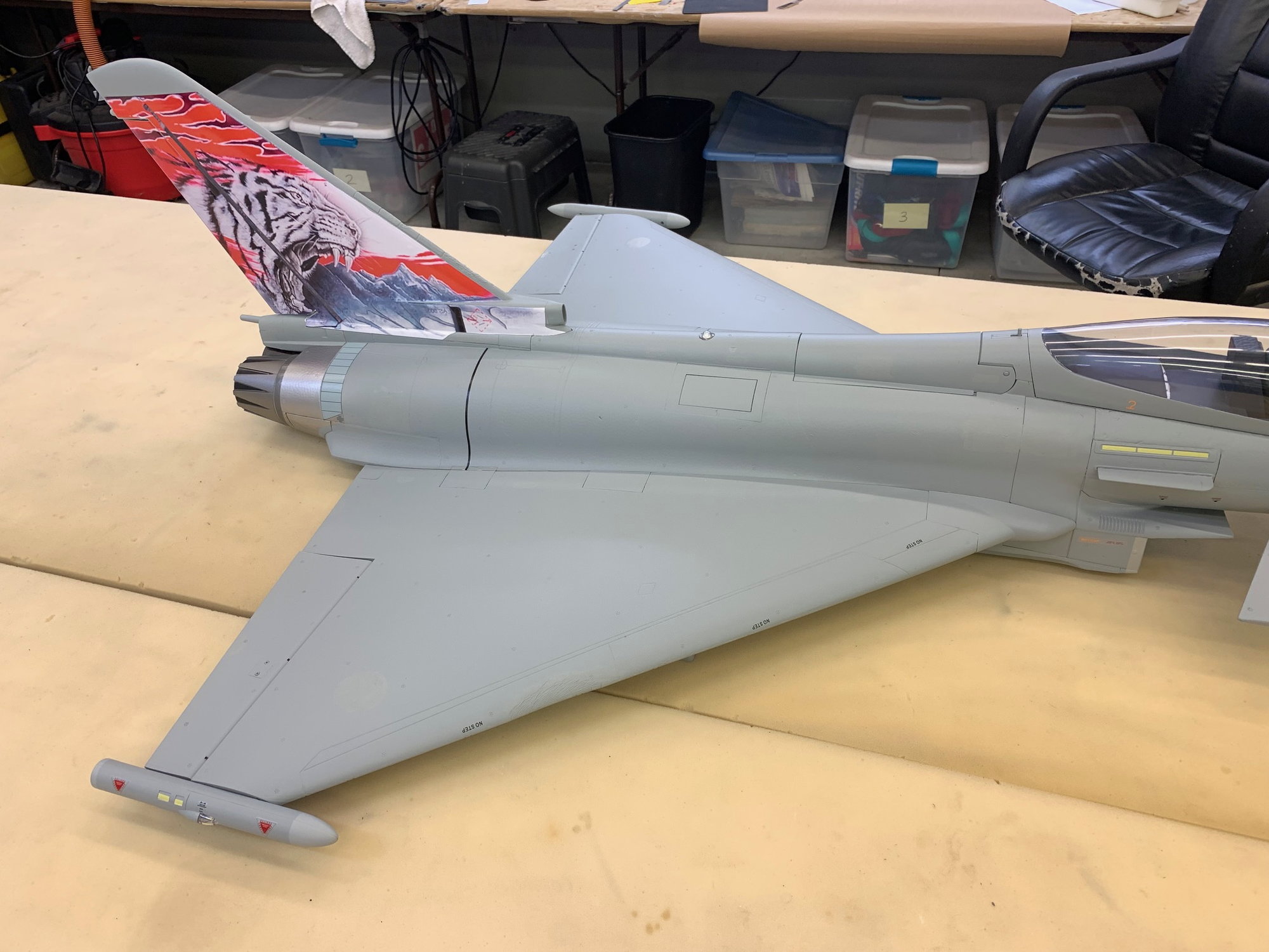
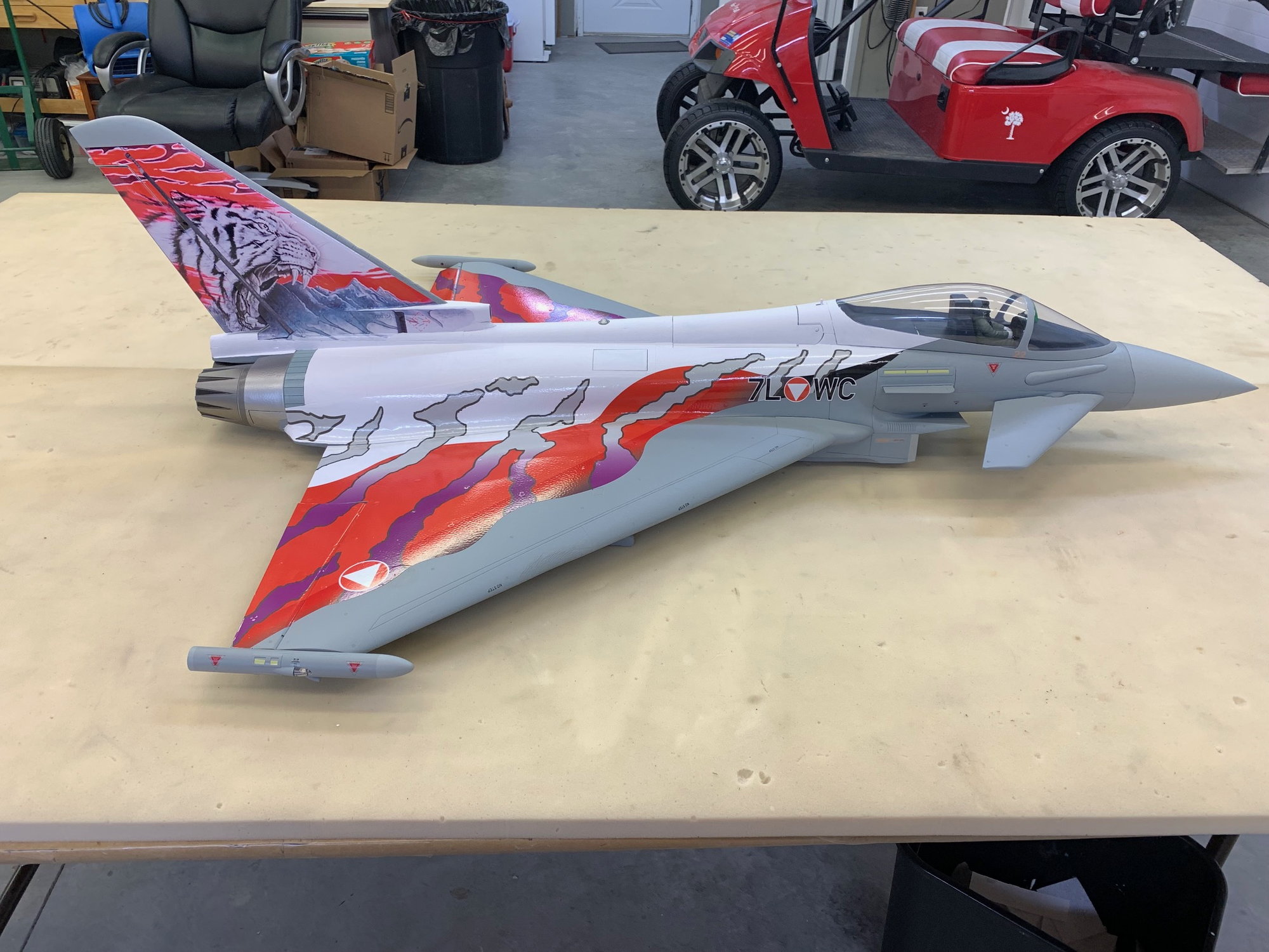
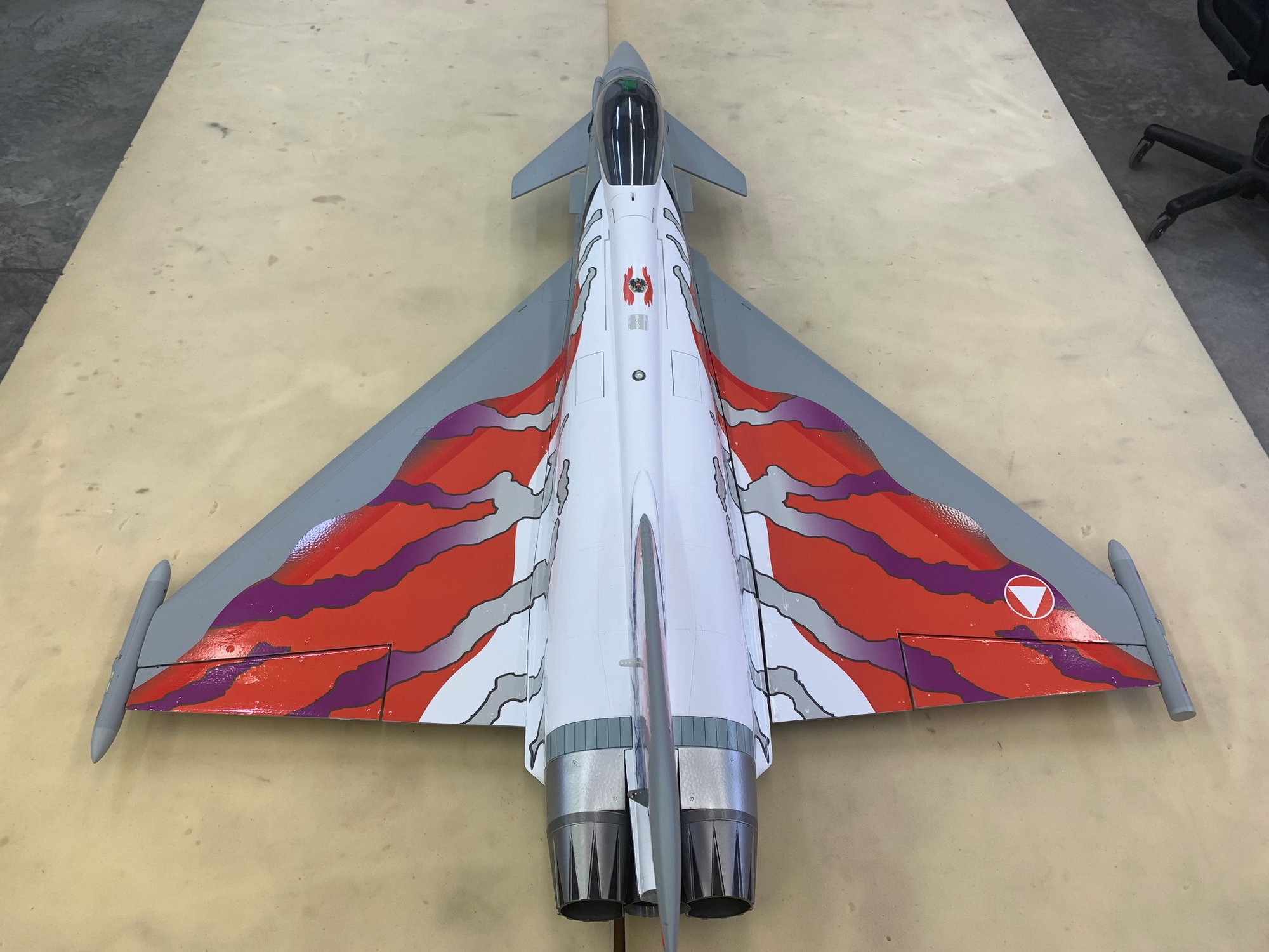
Top side happy snap.
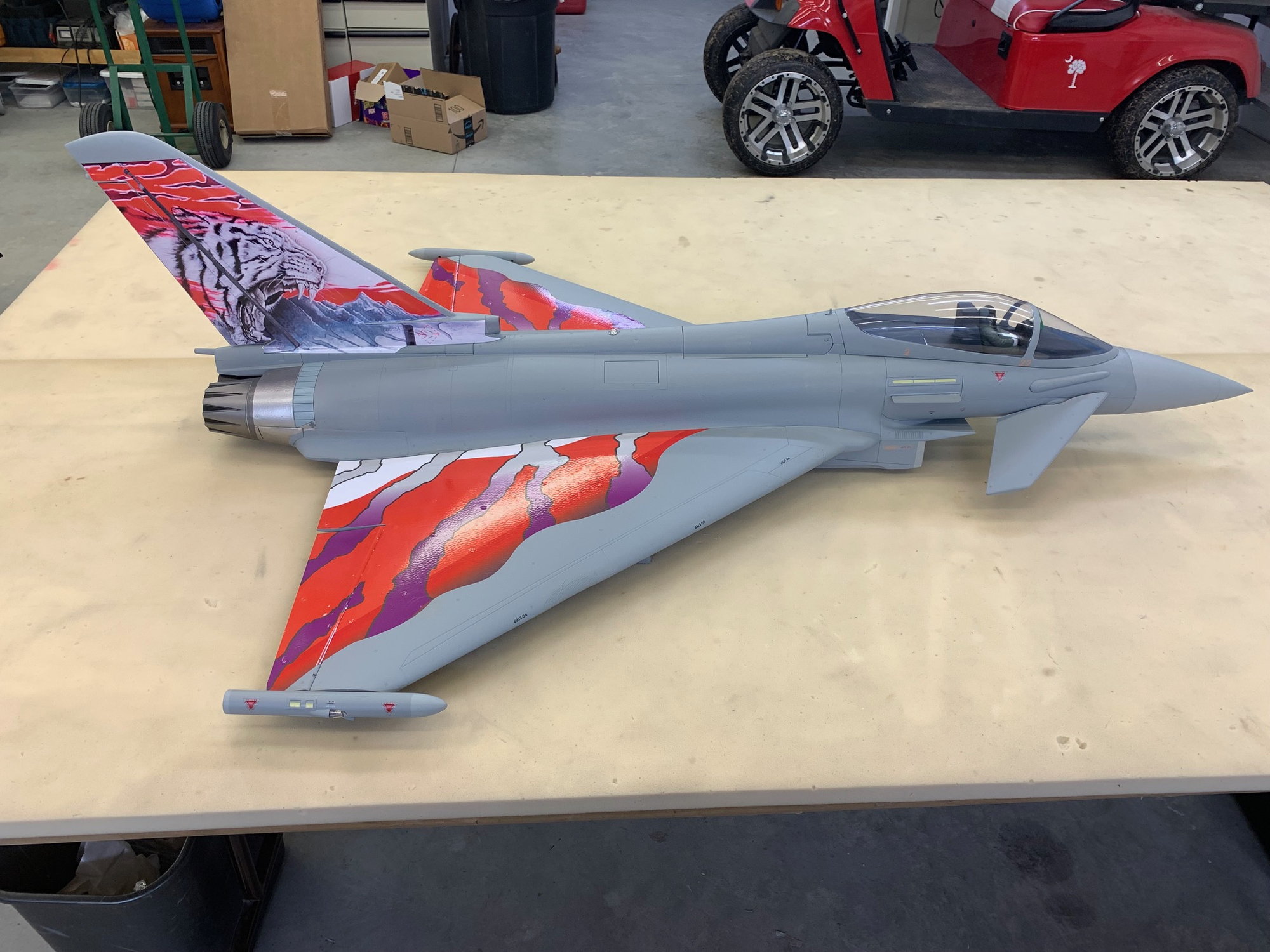
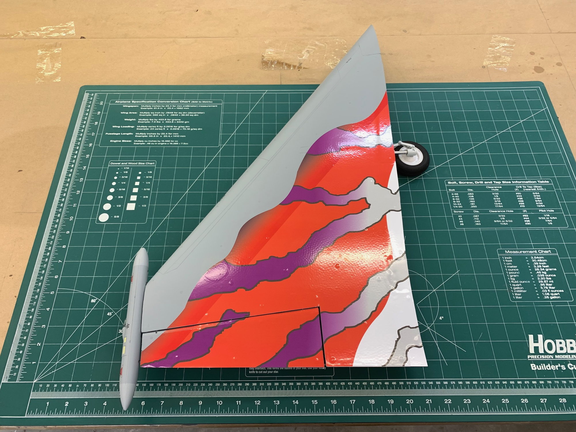
RIght side...

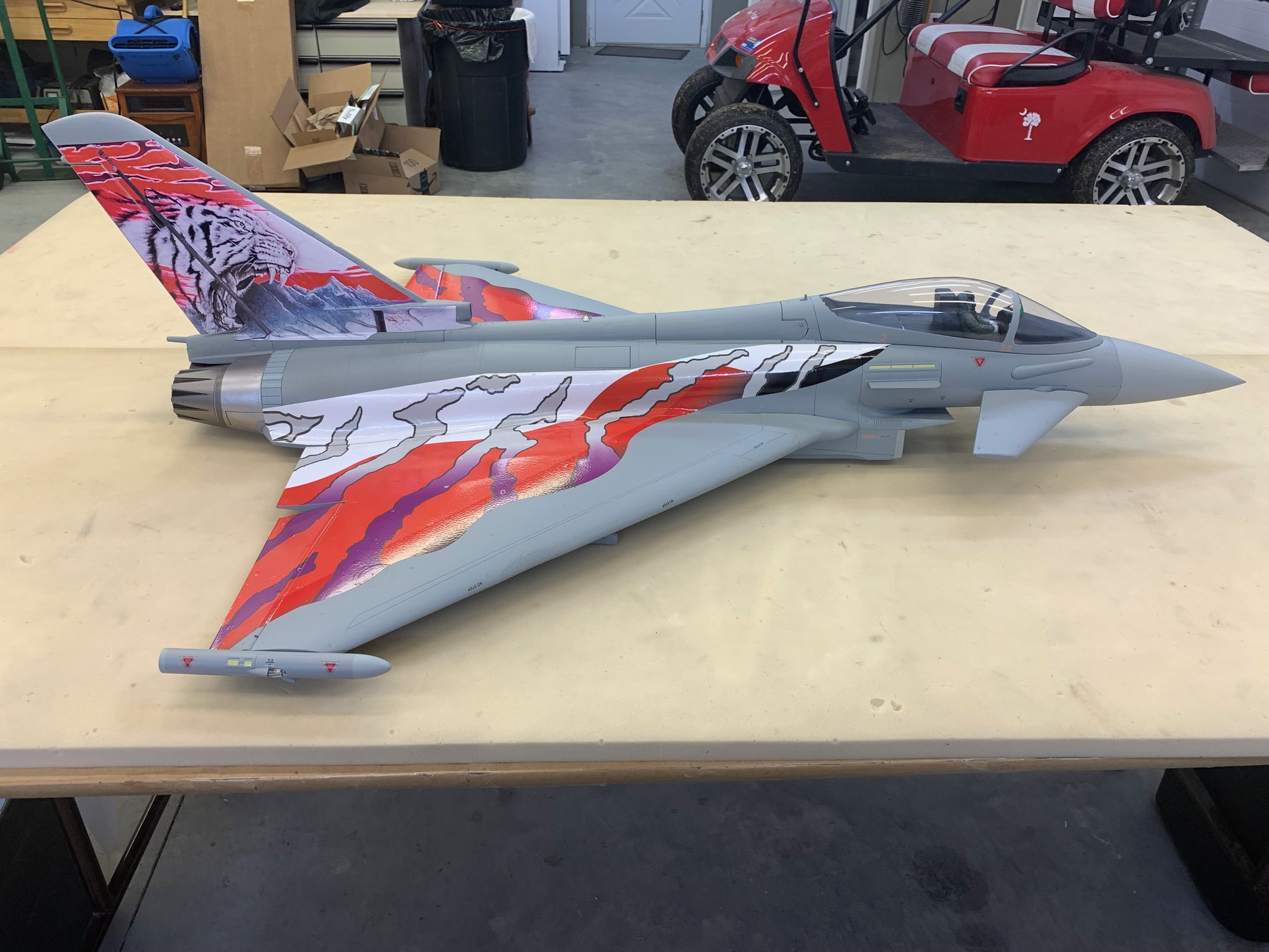
Left side. Fuse vinyl application next.
Clearance cuts between wing and elevon made from bottom with cutting board.
Straight edge used to make elevon hinge line cuts.
Vinyl after water squeezed out and edges rubbed down.
Top side happy snap.
RIght side...
Left side. Fuse vinyl application next.
The following users liked this post:
jcterrettaz (06-11-2023)
06-11-2023, 03:26 PM
#69
Thread Starter
My Feedback: (20)
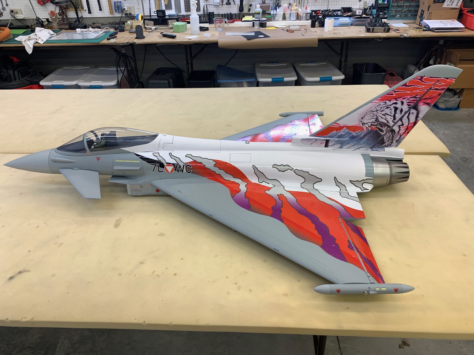
VInyl applied to fuse sides
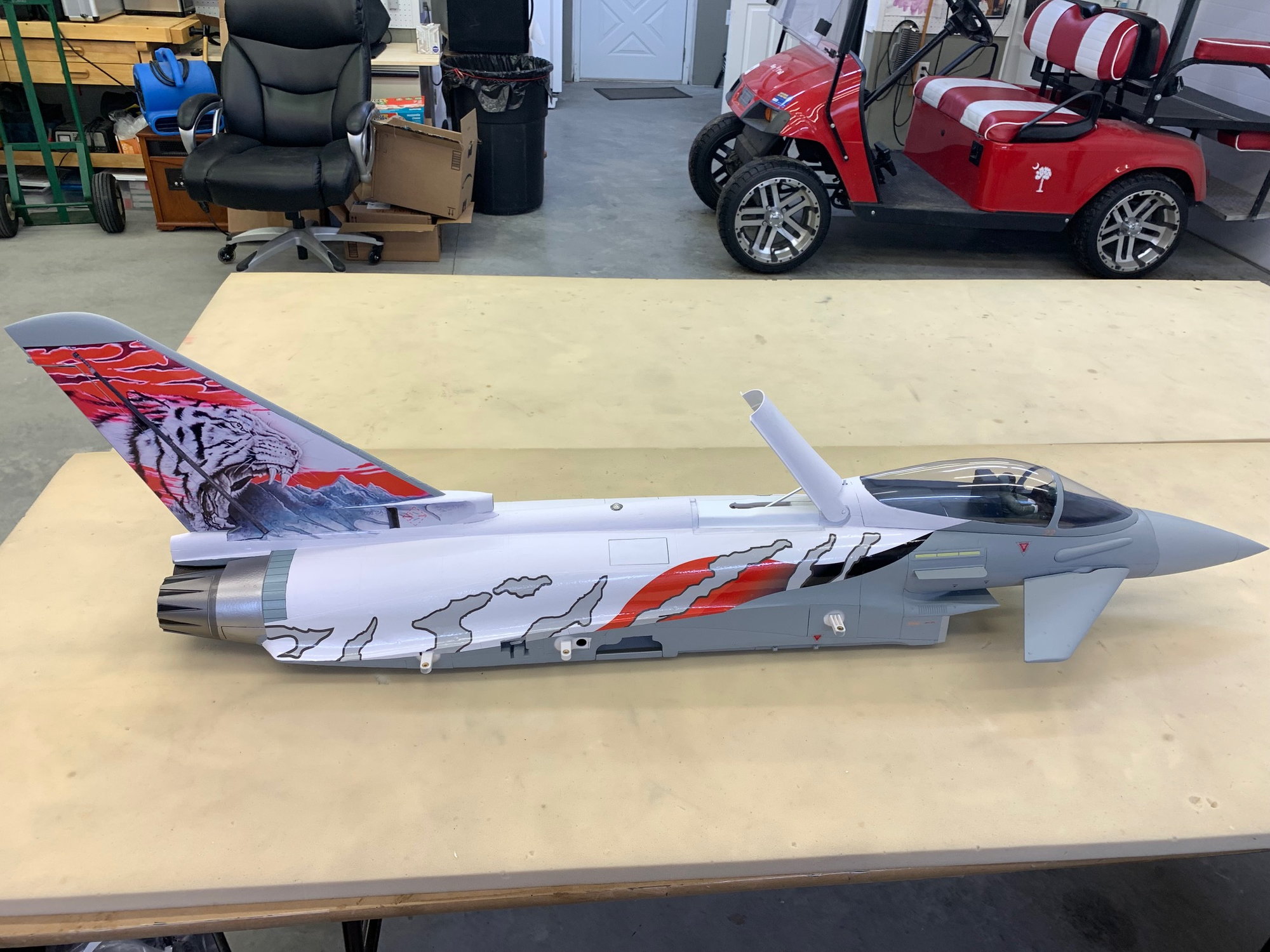
The vinyl was applied to the fuse sides using the alignment registration marks from the wings and panel line on the fuse. Due to compound curves I had to make multiple cuts just below the wing root line to allow it to lay down on the fuse sides. Its not perfect but close enough.

I was a little disappointed that the graphics did not extend farther up on the fuse sides like the full scale does. Hopefully the white paint on the top of the fuse will tie it all together.
The vinyl was applied to the fuse sides using the alignment registration marks from the wings and panel line on the fuse. Due to compound curves I had to make multiple cuts just below the wing root line to allow it to lay down on the fuse sides. Its not perfect but close enough.
I was a little disappointed that the graphics did not extend farther up on the fuse sides like the full scale does. Hopefully the white paint on the top of the fuse will tie it all together.
The following users liked this post:
dr.tom (06-13-2023)

The following users liked this post:
Viper1GJ (06-12-2023)
06-14-2023, 05:08 PM
#73
Thread Starter
My Feedback: (20)
White paint applied to fuse
White paint applied to top of fuse freehand with watercolor brushes. Only tape used was on canopy.
Speed brake opened to paint edges.
Insignia and lettering applied.
A couple more decals to go on fuse and vertical fin. Then it will get 2 coats of flat Polycrylic to seal the decals and make everything the same sheen.
The following users liked this post:
dr.tom (06-14-2023)
06-15-2023, 03:53 PM
#74
Thread Starter
My Feedback: (20)
Final markings applied
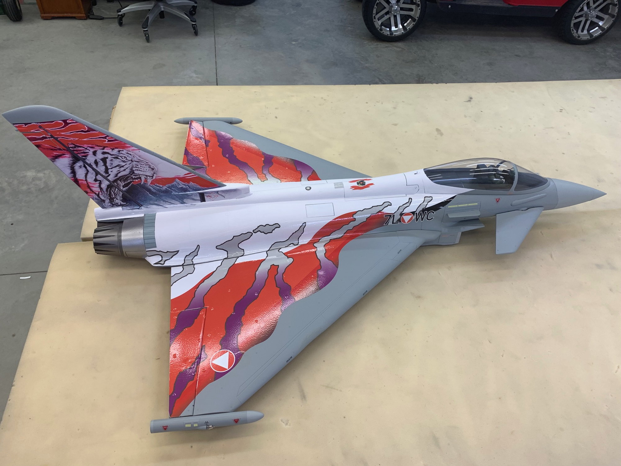
Final decals applied.
My best effort to add the Austrian Air Force crest on the speed brake and the grey panel behind the speed brake.
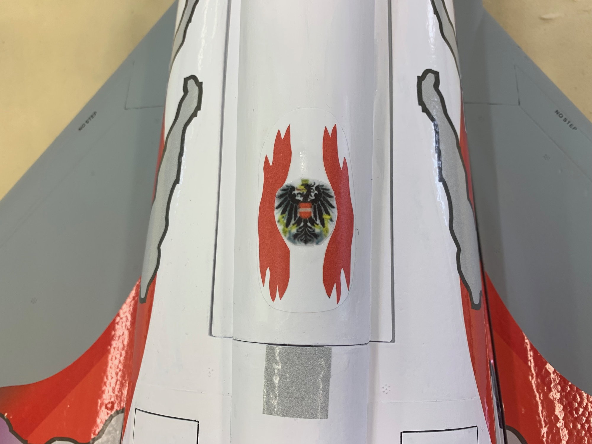
I used a paper print out of the crest lifted from the internet. The red flashes were hand cut from some of the red vinyl left over from the wing graphics. It was all stuck to some left over white and then placed on the speed brake. It's not exact but helps break up the wite field on top of the fuse. The crest has 2 coats of flat Polycrylic and you can see the difference from the red on the wings. I'll coat the rest of the jet with flat Polycrylic next.
Final decals applied.
My best effort to add the Austrian Air Force crest on the speed brake and the grey panel behind the speed brake.
I used a paper print out of the crest lifted from the internet. The red flashes were hand cut from some of the red vinyl left over from the wing graphics. It was all stuck to some left over white and then placed on the speed brake. It's not exact but helps break up the wite field on top of the fuse. The crest has 2 coats of flat Polycrylic and you can see the difference from the red on the wings. I'll coat the rest of the jet with flat Polycrylic next.
06-15-2023, 08:49 PM
#75
Looks way better than standard Gary! I'm in the Austrian Alps at the moment on holiday and a real one flew by, off in the distance. It would be quite amazing for the pilot flying at high speed through these incredible valleys throughout the Alps.