


T-One Models F22 Raptor build thread


 02-06-2020, 04:03 AM
#52


I have brass tubes pressed into some ply. I then glued that over the vent screens on the belly. That way the vents cant be seen. If you use a taxi tank that wont work for you though. I never use them so it works for me. I hate seeing vents and don't like getting fuel all over my self or spotter every flight.
I will probably install them tonight to show you. One thing I did learn is to use the rear vent screen. On my first one I used the forward one and fuel that was vented out would blow into the screen behind it.
I will probably install them tonight to show you. One thing I did learn is to use the rear vent screen. On my first one I used the forward one and fuel that was vented out would blow into the screen behind it.
02-10-2020, 01:55 PM
#54
Sorry for the delay had some other stuff to get done. But I�m back on it now.
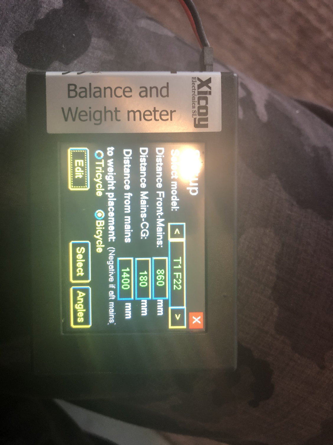
Here is the screen shot from my Xicoy balancer.
The official CG is 285MM back from the leading edge on the wing to fuselage joint. This CG felt great for me and I am not a fan of tail heavy aircraft so might have room to move it back but I liked it at 285.
the factory will say 255 to 265 and that is crazy nose heavy. If your doing twins you will need lots of lead in the nose. If you use the factory cg you might as well stick a bowling ball in it.
02-10-2020, 02:32 PM
#55
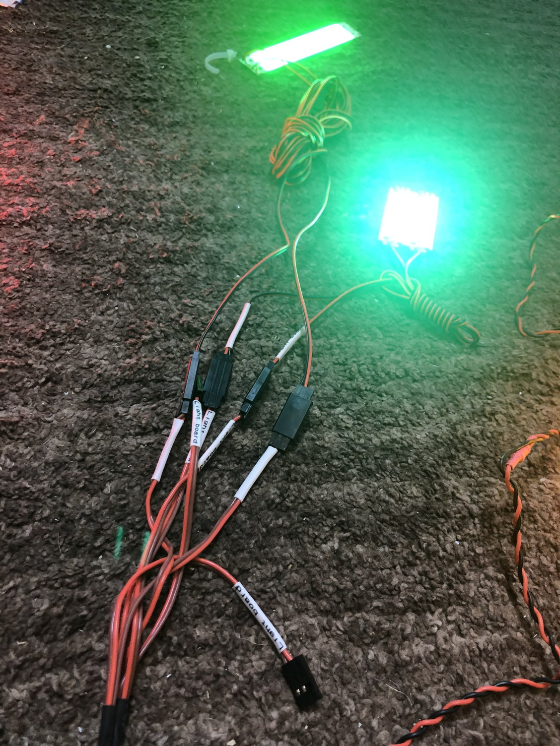
Hey Gun can you explain the light controller? Mine has three leads on it, one say gear signal, one says switch, and the third says control signal for nozzle lamp.
The controller has three large, what appears to be voltage regs and each has two leads/plugs coming from it. So do u plug the slime lights into the voltage regulator leads and the reds/green/landing lights into the pins on the controller?
The controller has three large, what appears to be voltage regs and each has two leads/plugs coming from it. So do u plug the slime lights into the voltage regulator leads and the reds/green/landing lights into the pins on the controller?
02-10-2020, 03:11 PM
#56
Hey Gun can you explain the light controller? Mine has three leads on it, one say gear signal, one says switch, and the third says control signal for nozzle lamp.
The controller has three large, what appears to be voltage regs and each has two leads/plugs coming from it. So do u plug the slime lights into the voltage regulator leads and the reds/green/landing lights into the pins on the controller?
The controller has three large, what appears to be voltage regs and each has two leads/plugs coming from it. So do u plug the slime lights into the voltage regulator leads and the reds/green/landing lights into the pins on the controller?
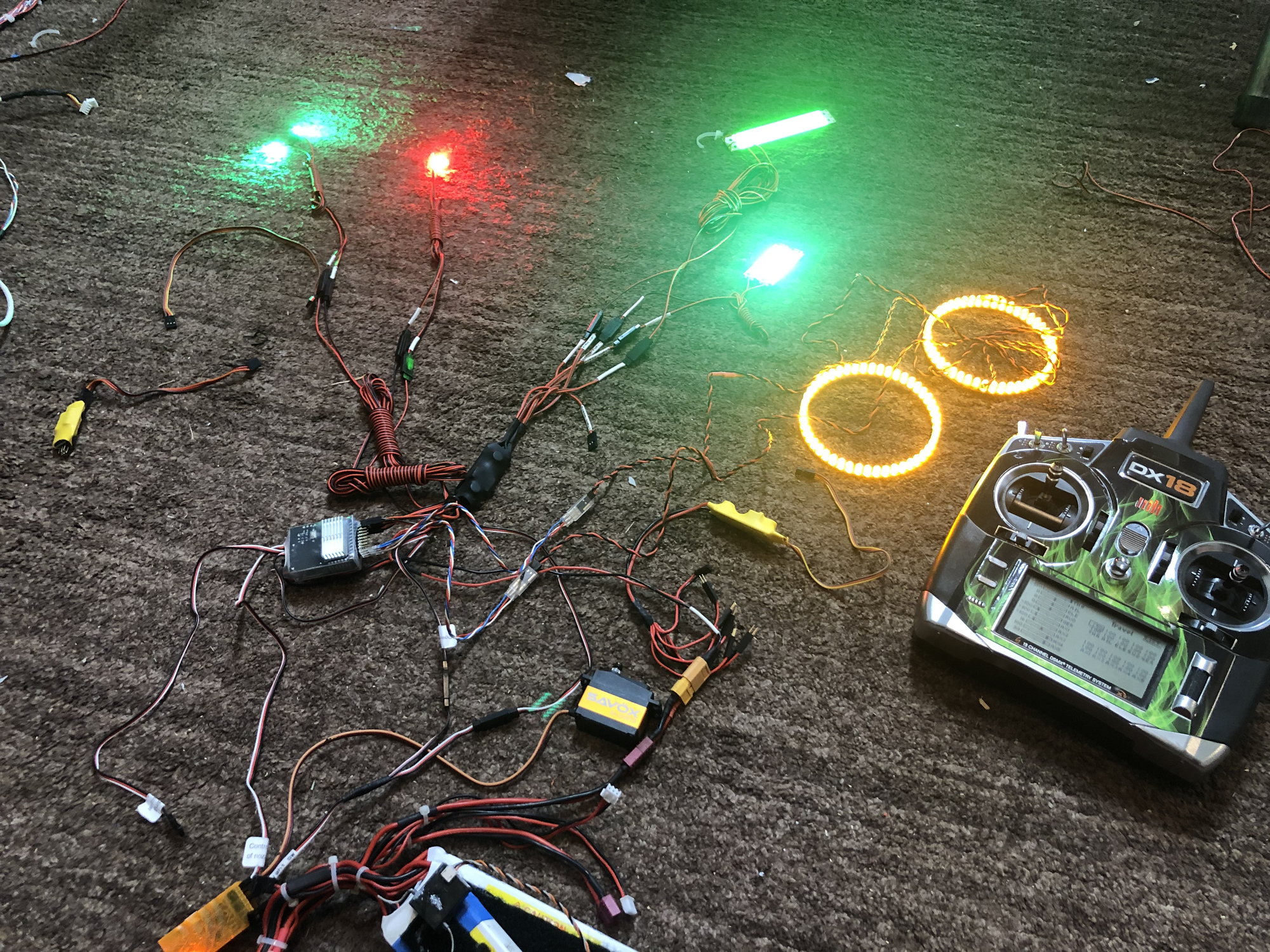
i laid it all out on the floor and got it.
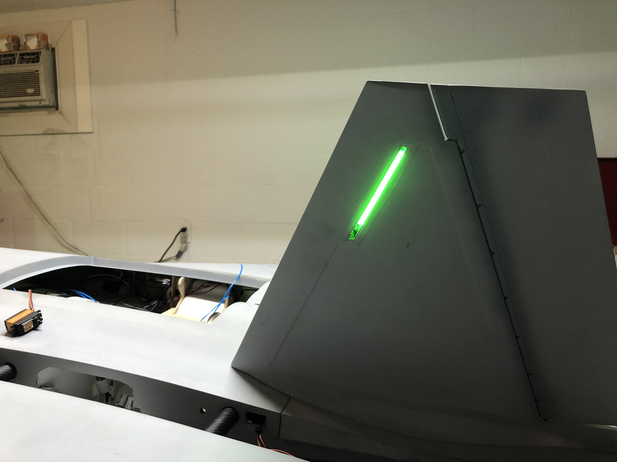
yes the nav lights landing lights plug right into the controller. Some of the outputs blink and some are on all the time.
the slime lights run on a different voltage so they have the big resistor and wires.
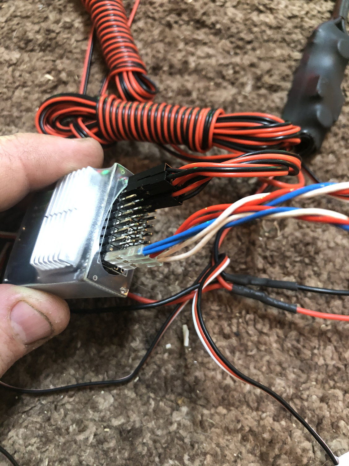
switch goes to the receiver.
AB goes to throttle. The AB output is the one lead on the output side all alone. It�s spaced out one connection away from the rest.
landing light connection goes to receiver.
02-10-2020, 03:16 PM
#57
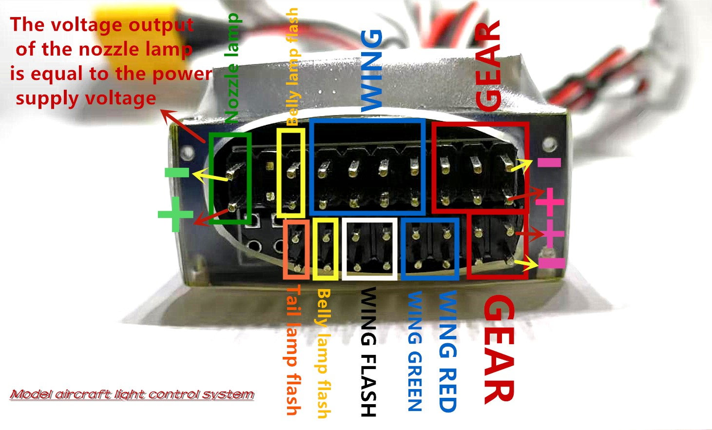
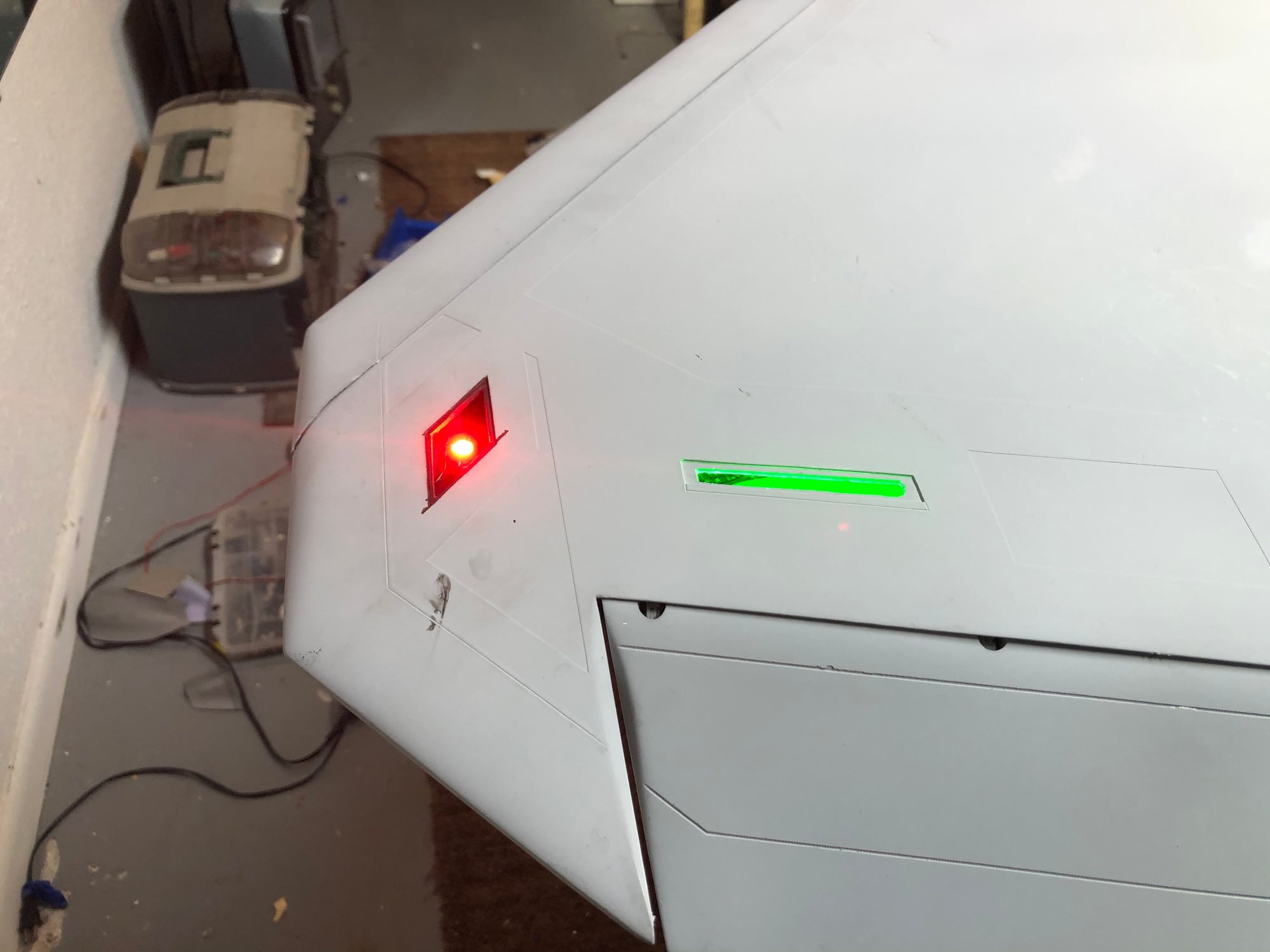
After having so many issues with the old light controller T1 made a new one. They made it very simple no frills but it�s supposed to be very reliable.
the rings are 95mm AirPower rings from Dreamworks . They work great with the stock controller. I did extend the end points and it will need to be on its own channel.
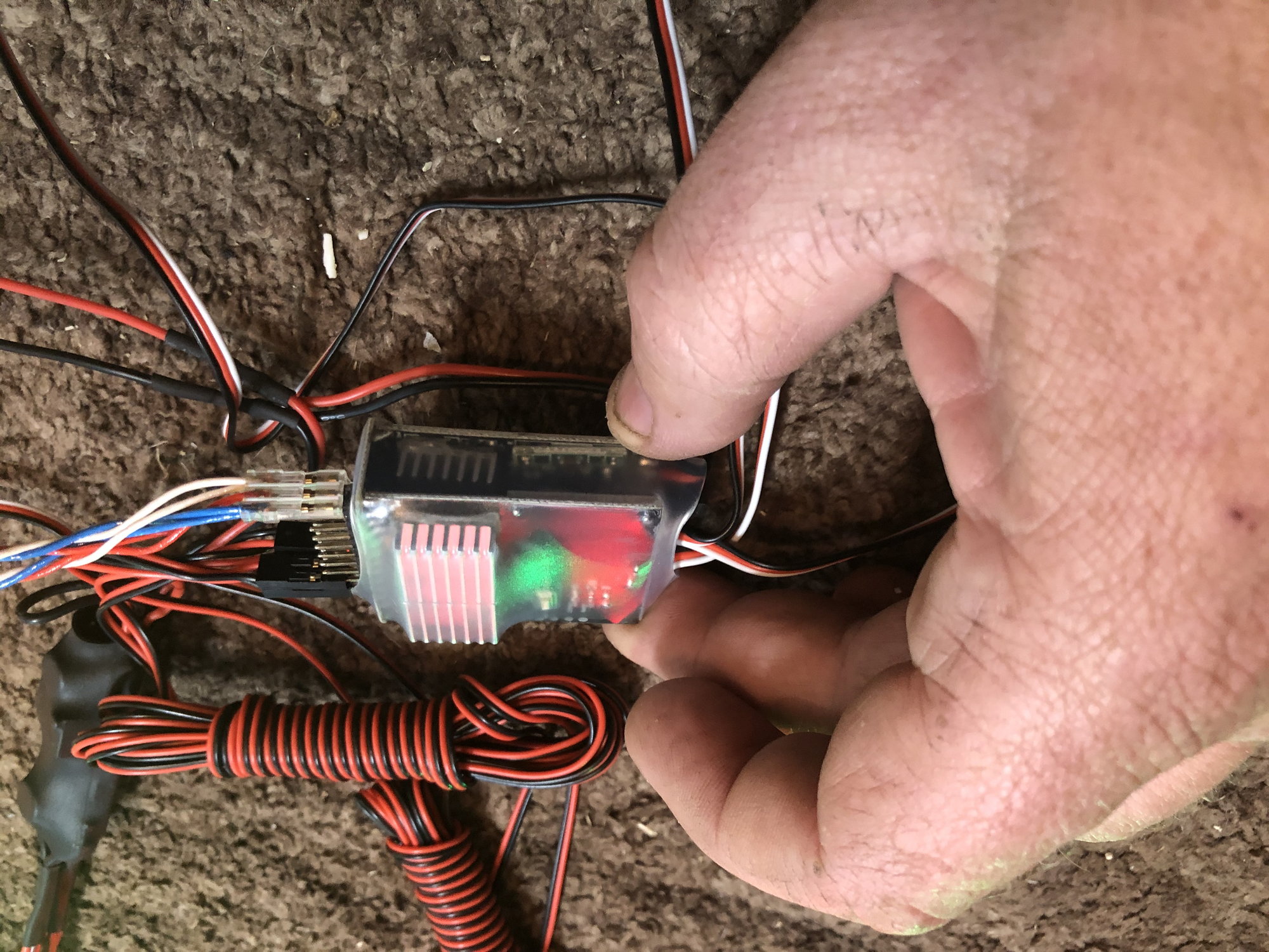
the rings are 95mm AirPower rings from Dreamworks . They work great with the stock controller. I did extend the end points and it will need to be on its own channel.
02-10-2020, 03:50 PM
#58
I have the same controller but mine is different from yours, I managed to figure it out. The one I have is simple once you figure it out, I plugged gear signal into gear channel, the switch is plugged into an aux channel or a switch. I plugged it into an aux channel and the formation lights come on, I guess the last plug is for afterburner rings.
02-10-2020, 04:39 PM
#59
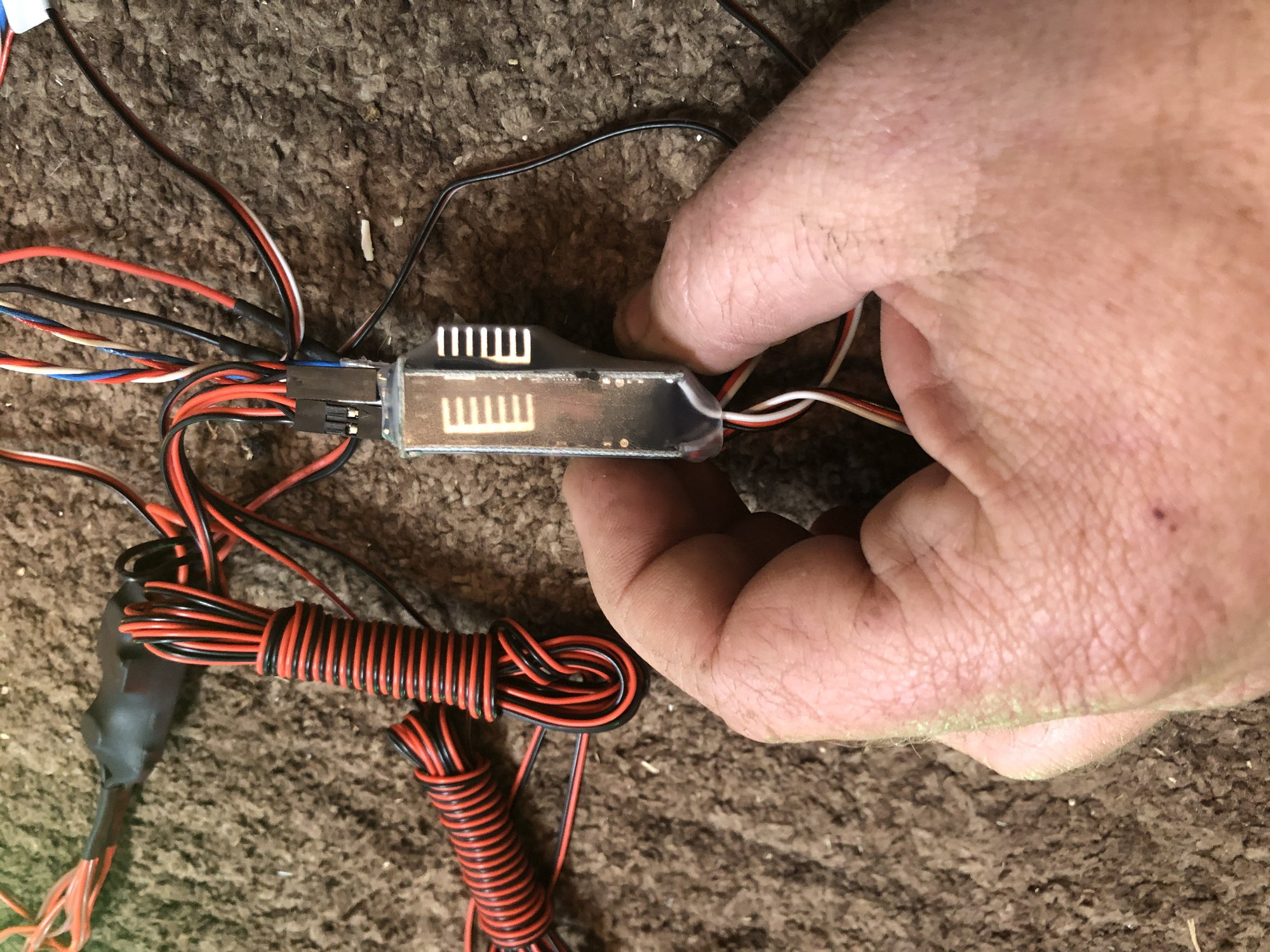
The new controller will work from 4.5 volts up to a 3 cell LIFE. So no need to use lipos anymore. That was the biggest complaint of mine. I hate having a separate little Lipo just for the lights.
do not use a 3 cell Lipo that will be to much. 3 cell Life is the max.
do not use a 3 cell Lipo that will be to much. 3 cell Life is the max.
02-10-2020, 04:47 PM
#60
02-10-2020, 06:54 PM
#62
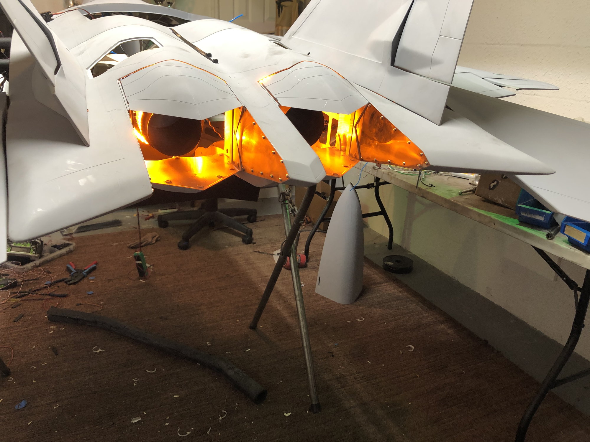
Busy night.
got the rear end wired up and joined at the fuselage.
I will be filling the joint so it�s not going to come apart again after this. So really got to think ahead and get everything installed before it�s joined. Pipe must go in before it�s joined. So all the alignment must be done prior too.
pics are not loading. Will try tomorrow
02-10-2020, 07:52 PM
#63
Yelp, I and the low number of lights I want have to worry about voltage drop with the a lower voltage either. I have everything in mine and doing final setup/running wires, should be done by this weekend!
02-11-2020, 11:06 PM
#64

 02-12-2020, 10:59 AM
#65
Ok guys. Talked to the factory this morning and got the issue with the rudders figured out. So when assembling the rudders I would assume they did all the right ones in a batch. They ran out of the splined shafts so they got a new batch of them. When doing a batch for left rudders they are slightly undersized. The factory will come up with a fix and send new parts to Dirk to send out to all of us. I would imagine it would be pressing out the smaller T shaft and pressing in the correct size shaft. Its going to be a little while until they can get back to work though because they are not allowed to work right now because of the virus outbreak. Hopefully in a few weeks something might be in the works. Thanks everyone for bringing this to our attention.
 02-13-2020, 04:37 AM
#69
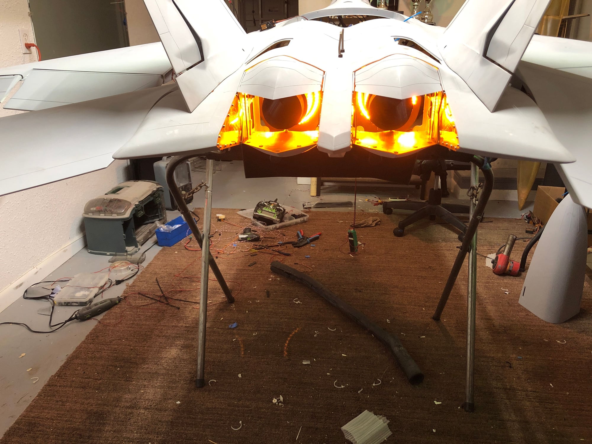
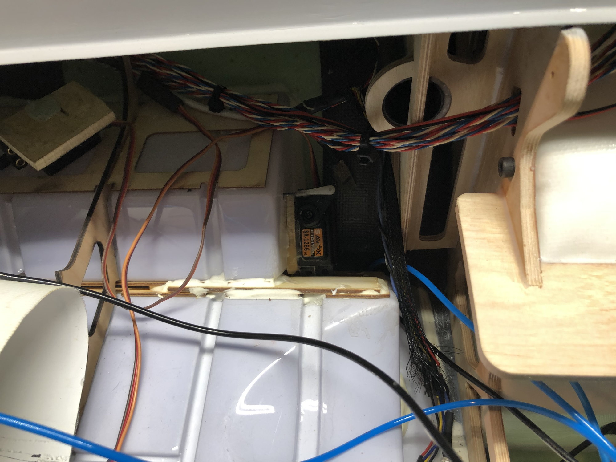
Doing the pain in the butt part now. Getting all these wires ran to the front. Got both sides done and tested the lightning system installed. It all works so moving forward.
the AB system on the light controller puts out what ever it receives so it�s not regulated like the other lights. So after some testing the 3cell LIFE does the ring best with no overheating of the bulbs. So will make a harness and tap lights off the ECU battery.
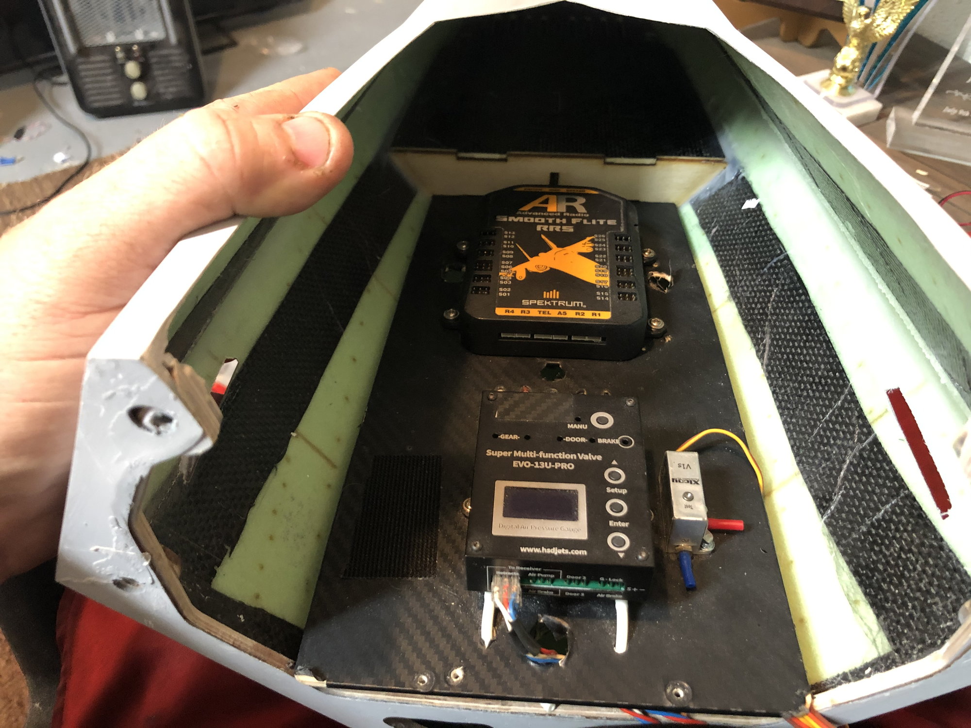
also started fitting the equipment. Was going to reuse the panels from the prototype but the internals on this production version are different so need to do some trimming and other fitting.
the AB system on the light controller puts out what ever it receives so it�s not regulated like the other lights. So after some testing the 3cell LIFE does the ring best with no overheating of the bulbs. So will make a harness and tap lights off the ECU battery.
also started fitting the equipment. Was going to reuse the panels from the prototype but the internals on this production version are different so need to do some trimming and other fitting.
02-13-2020, 04:39 AM
#70
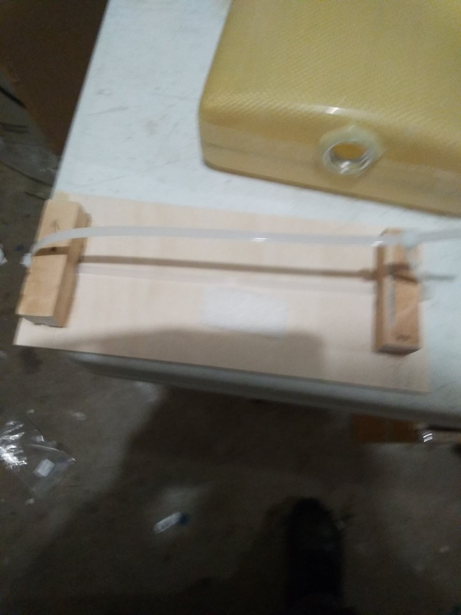
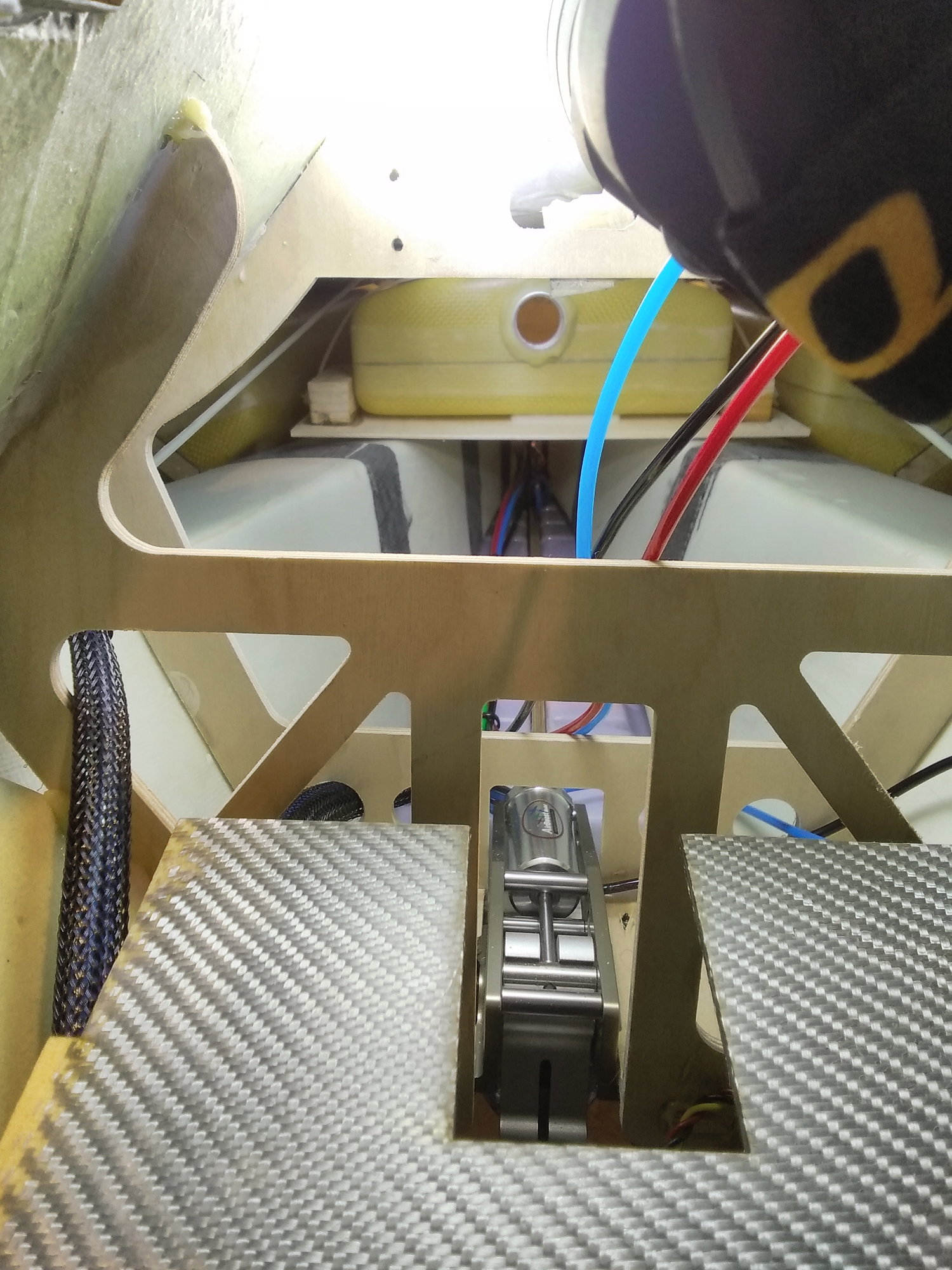
For the main fuel tank. I think David was asking how to secure it. When I get a little further I will show how I did it. Basically though I have a service panel in the engine bay for charging , air and other things. That panel gets screwed into some wood I hysol to each saddle tank and the main tank.
02-13-2020, 06:17 AM
#71

My Feedback: (15)
For the main fuel tank. I think David was asking how to secure it. When I get a little further I will show how I did it. Basically though I have a service panel in the engine bay for charging , air and other things. That panel gets screwed into some wood I hysol to each saddle tank and the main tank.
I made a simple tray with a couple of wood blocks and a zip which was glued in place. The main tank easily slips under the zip and is held firmly in place. A simple, but effective solution.
 02-14-2020, 06:34 AM
#72
Got one of the parts I was dreading done last night. Both missile ejector racks are done and working. Next up will be the dreaded gun door.
if you look at videos of the F22 there is a ton of detail inside the side ordinance bays. I have a friend sending my 3D printed scale parts for these areas. It is going to look good when done. After I try them out I�ll post pics and give out the contact info and pricing.
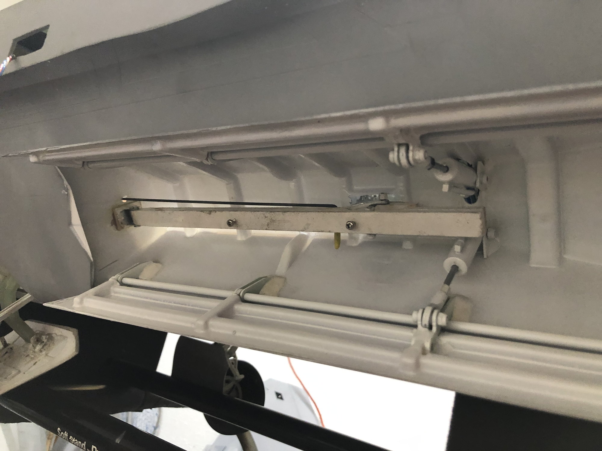
if you look at videos of the F22 there is a ton of detail inside the side ordinance bays. I have a friend sending my 3D printed scale parts for these areas. It is going to look good when done. After I try them out I�ll post pics and give out the contact info and pricing.
02-19-2020, 03:08 PM
#73
Hey Kris you mentioned using an inline restrictor on the mains to get the unlock to work properly. Did you just put the restrictor after the unlock T so the main cylinders fill slower, I tried that not work for me so far.
I was considering just adding another valve, the xicoy V1.
I was considering just adding another valve, the xicoy V1.
02-19-2020, 03:42 PM
#74
I can�t remember. I had restrictors I see on my main up gear lines near the actuators. But I also see an extra one way valve i took out of the plane. I can�t remember if I used that or not. I�ve built so many planes since then lol.
im almost to the point of swinging the gear. I only have the restrictors so I�ll let you know
im almost to the point of swinging the gear. I only have the restrictors so I�ll let you know
02-19-2020, 04:51 PM
#75
I can�t remember. I had restrictors I see on my main up gear lines near the actuators. But I also see an extra one way valve i took out of the plane. I can�t remember if I used that or not. I�ve built so many planes since then lol.
im almost to the point of swinging the gear. I only have the restrictors so I�ll let you know
im almost to the point of swinging the gear. I only have the restrictors so I�ll let you know