


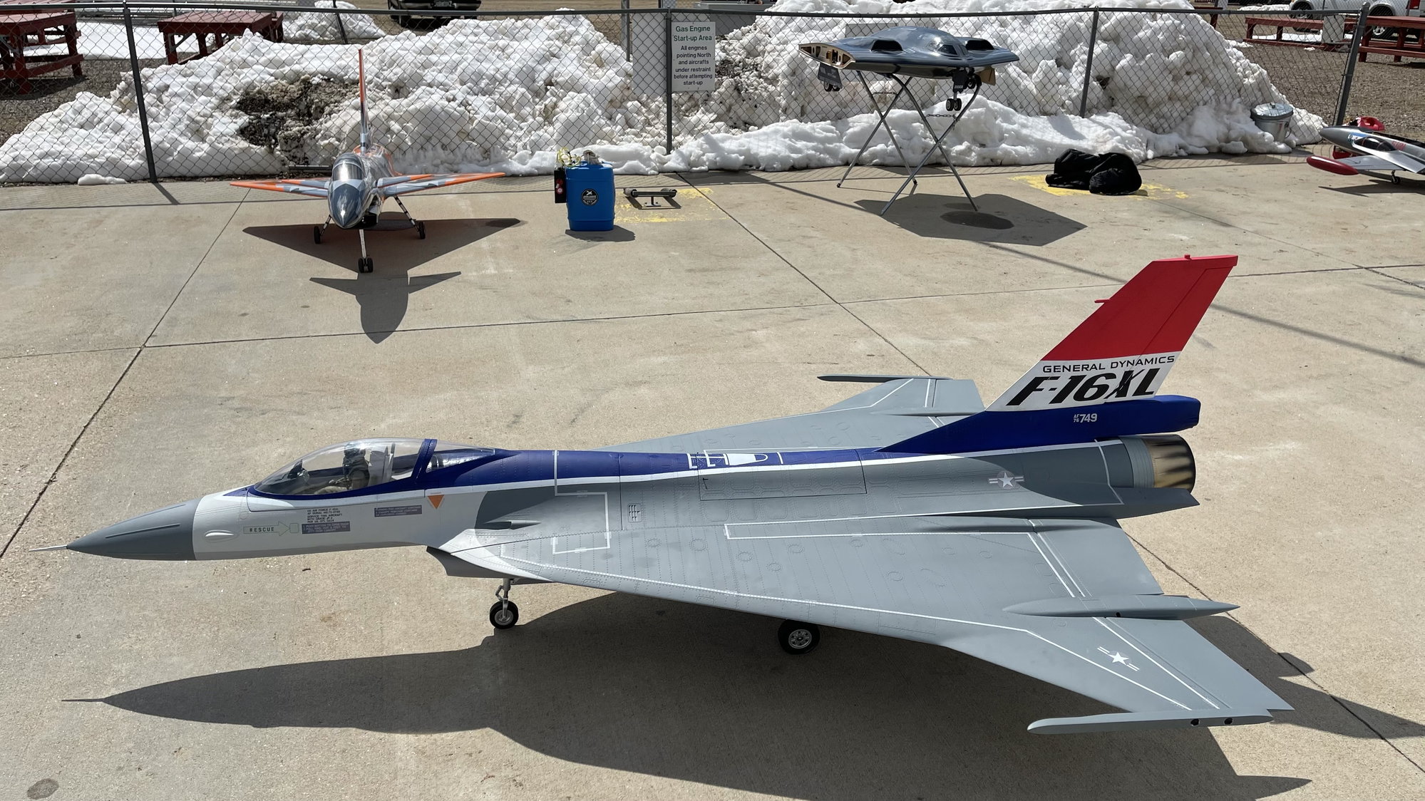
F-16XL ARF by Global Knight Models from Global Jet Club


 03-26-2021, 01:24 PM
#27

Thread Starter
My Feedback: (20)

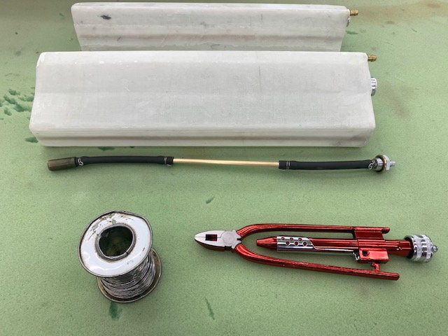
Pipe looks really nice with double rows of spot welds. It had some minor dents on the outer sleeve but they are of no factor in performance
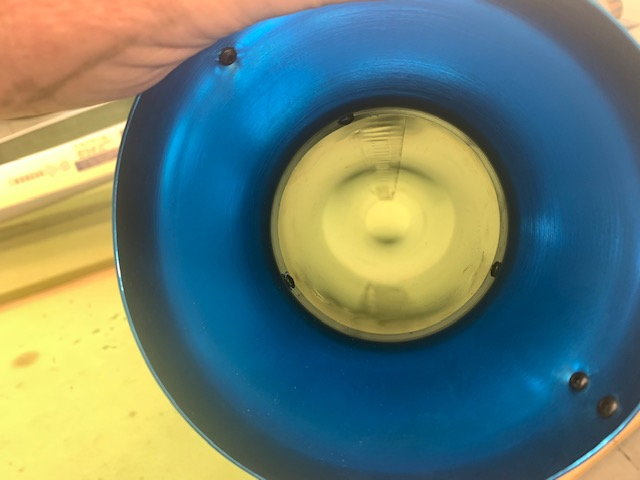
Inside tube is smooth and round

Pipe mounting tabs have very sharp corners. I cut my hand when unwrapping the pipe on the corner.
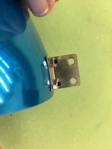
Fixed the corners with a dremel wheel
03-26-2021, 03:01 PM
#29
My Feedback: (2)
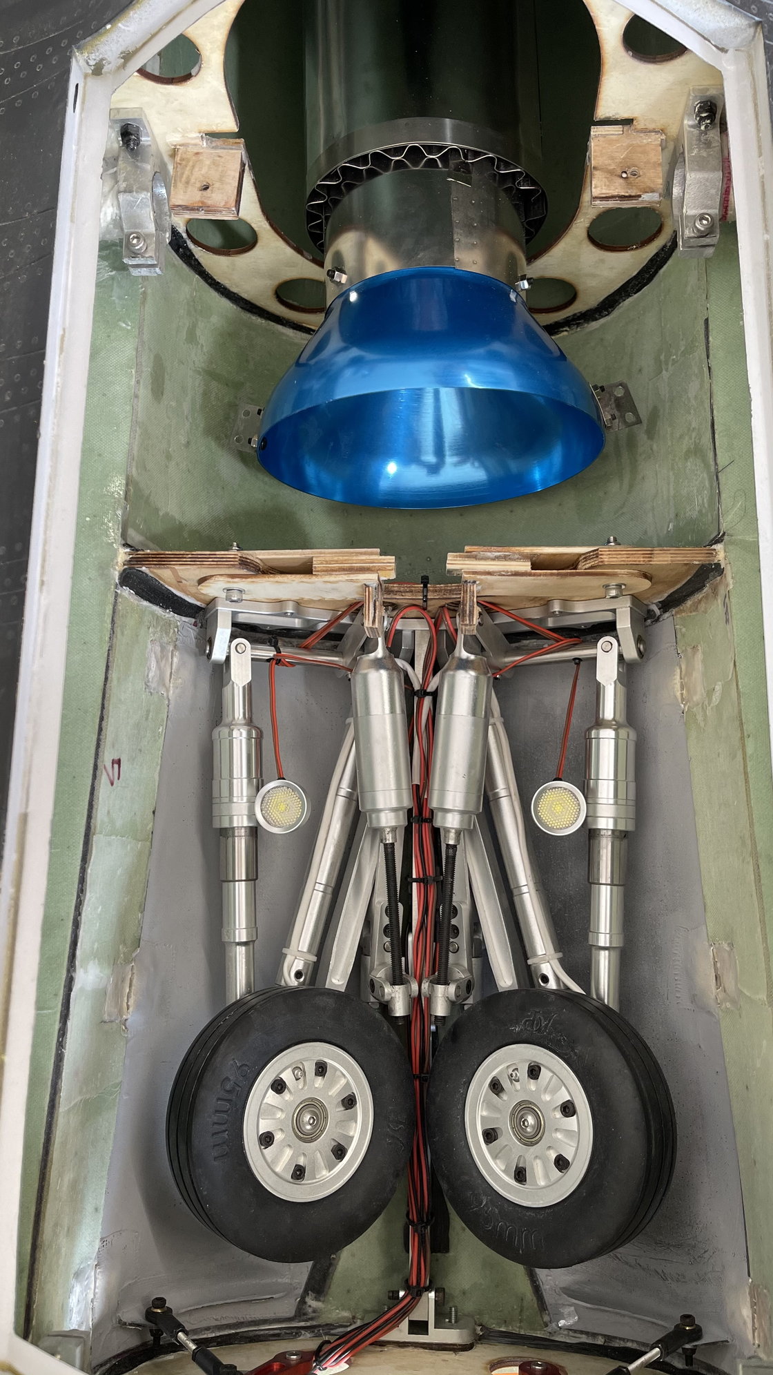
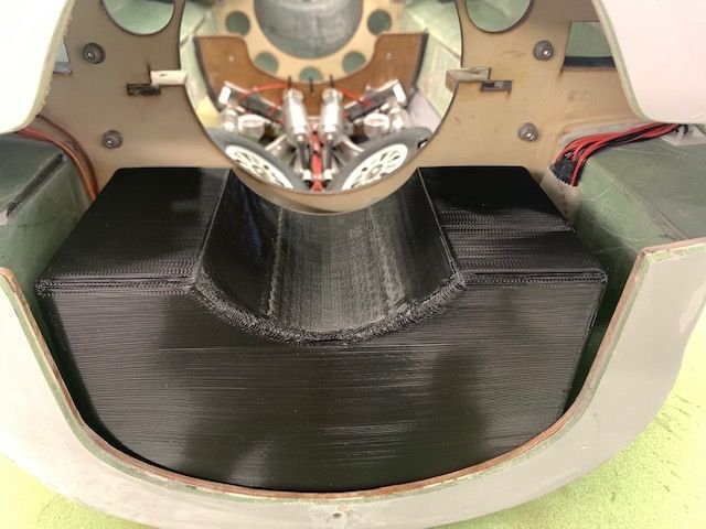
Saw that RC MAN mentioned about the concern around the former and fuse, we inspected it this morning, discussed it and determined it was fine, is it 110% perfect? no, but is enough not to be concerned about it? yes. Its all going to depend how your flying the XL, I'm more like Ali the way he fly his, I won't be trying to hit 200mph, hard banks, flips and spins lol, so for MY type of preference of flying and the fact the main landing gear is in the fuse and not in the wing it really depending on how much stress and high wing loading your going to put on it. It's stiffer than it looks in the picture and remember both sides have 2 reinforcement carbon points on each side, the wing itself is not too heavy. So for all the reasons above not going to do anything, for me I will keep an eye on it and inspect it during every flight, it's easy to inspect with the top engine hatch removed. Picture looking down at turbine shows how much the pipe was moved aft from its original point, same with turbine. Maiden flight is scheduled for tomorrow morning for the # 1 XL so I'll be able to upload a video sometime tomorrow afternoon.

03-26-2021, 06:21 PM
#31

Saw that RC MAN mentioned about the concern around the former and fuse, we inspected it this morning, discussed it and determined it was fine, is it 110% perfect? no, but is enough not to be concerned about it? yes. Its all going to depend how your flying the XL, I'm more like Ali the way he fly his, I won't be trying to hit 200mph, hard banks, flips and spins lol, so for MY type of preference of flying and the fact the main landing gear is in the fuse and not in the wing it really depending on how much stress and high wing loading your going to put on it. It's stiffer than it looks in the picture and remember both sides have 2 reinforcement carbon points on each side, the wing itself is not too heavy. So for all the reasons above not going to do anything, for me I will keep an eye on it and inspect it during every flight, it's easy to inspect with the top engine hatch removed. Picture looking down at turbine shows how much the pipe was moved aft from its original point, same with turbine. Maiden flight is scheduled for tomorrow morning for the # 1 XL so I'll be able to upload a video sometime tomorrow afternoon.
It looks like it is just secured by that wrap of carbon cloth. It does not appear to have any mechanical attachment to the bulkhead. That doesn't look like it can take very much wing bending load at all. It really needs something like another clamp block at the outboard end mechanically tied into the bulkhead to transfer the wing bending loads into the bulkhead..
Paul
 03-27-2021, 04:49 AM
#33
Thread Starter
My Feedback: (20)
RC_MAN the jet requires 5 standard size servos for flight controls and one mini (not micro) for steering. Torque is not specified in the build guide. I'm using 630 in flight controls and 355 in steering.
https://www.promodeler.com/DS630BLHV
https://www.promodeler.com/DS355CLHV
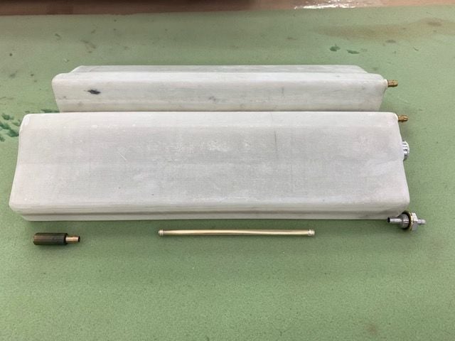
Here is the pipe.
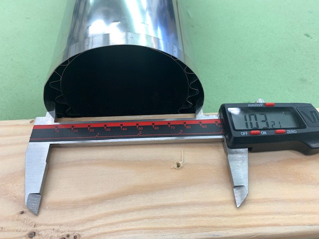
Outside diameter is 103mm

Inside diameter is 86m

Bell is 140mm
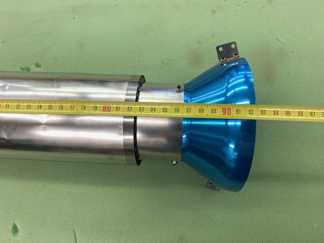
Length of pipe is 86.5cm and 92.5cm with bell
https://www.promodeler.com/DS630BLHV
https://www.promodeler.com/DS355CLHV
Here is the pipe.
Outside diameter is 103mm
Inside diameter is 86m
Bell is 140mm
Length of pipe is 86.5cm and 92.5cm with bell
03-27-2021, 05:08 AM
#34
Thread Starter
My Feedback: (20)
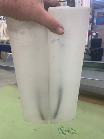
First draft 3D print fuel tank
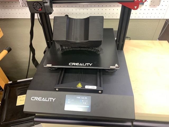
Printer finished sometime last night with the first draft of the forward fuel tank. I don't know how to use CAD stuff but my buddy Keith can send me STL files and I am just getting dangerous enough to get something off the printer.

Just off the printer with supports still attached. This first draft tank was made just for testing and only has 2 shell thickness. It is good enough for test fitting and making any mods needed.
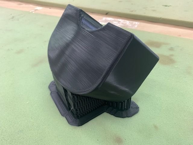
Keith suggested printing the final version in two parts to allow some internal structure for extra strength on the front and rear faces and then joining similar to a conventional tank. Final version will be printed with a translucent PETG. Estimated volume is 55-60oz.
Printer finished sometime last night with the first draft of the forward fuel tank. I don't know how to use CAD stuff but my buddy Keith can send me STL files and I am just getting dangerous enough to get something off the printer.
Just off the printer with supports still attached. This first draft tank was made just for testing and only has 2 shell thickness. It is good enough for test fitting and making any mods needed.
Keith suggested printing the final version in two parts to allow some internal structure for extra strength on the front and rear faces and then joining similar to a conventional tank. Final version will be printed with a translucent PETG. Estimated volume is 55-60oz.


The following users liked this post:
Viper1GJ (03-27-2021)
03-27-2021, 11:21 AM
#37
Thread Starter
My Feedback: (20)
What is supporting the outer end of the wing joiner tube?
It looks like it is just secured by that wrap of carbon cloth. It does not appear to have any mechanical attachment to the bulkhead. That doesn't look like it can take very much wing bending load at all. It really needs something like another clamp block at the outboard end mechanically tied into the bulkhead to transfer the wing bending loads into the bulkhead..Paul
It looks like it is just secured by that wrap of carbon cloth. It does not appear to have any mechanical attachment to the bulkhead. That doesn't look like it can take very much wing bending load at all. It really needs something like another clamp block at the outboard end mechanically tied into the bulkhead to transfer the wing bending loads into the bulkhead..Paul
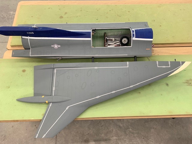
Wing tubes on right wing. Looks like to me that most of the lift and G load into the fuse will be supported by the rear wing tube and a smaller amount by the front tube. Hopefully some of the aero guys can discuss this for me.

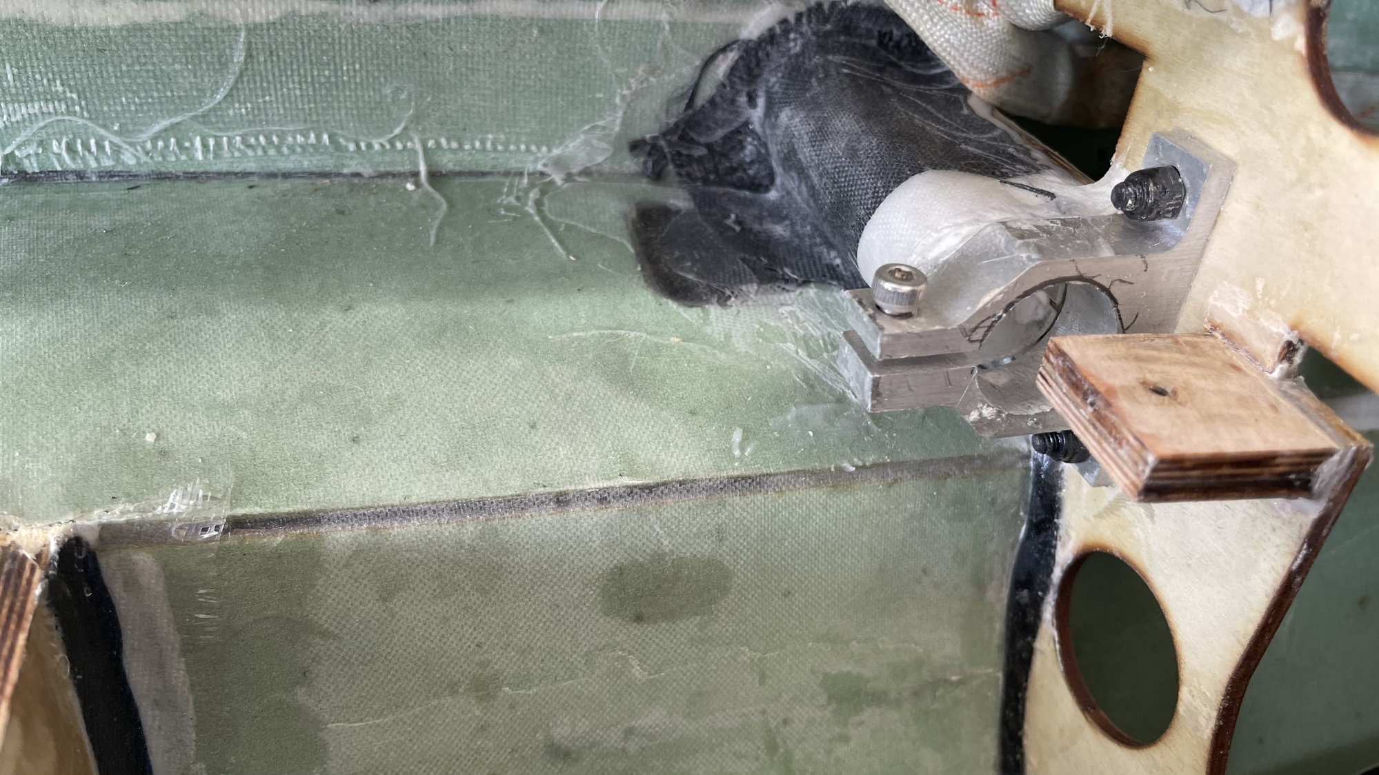
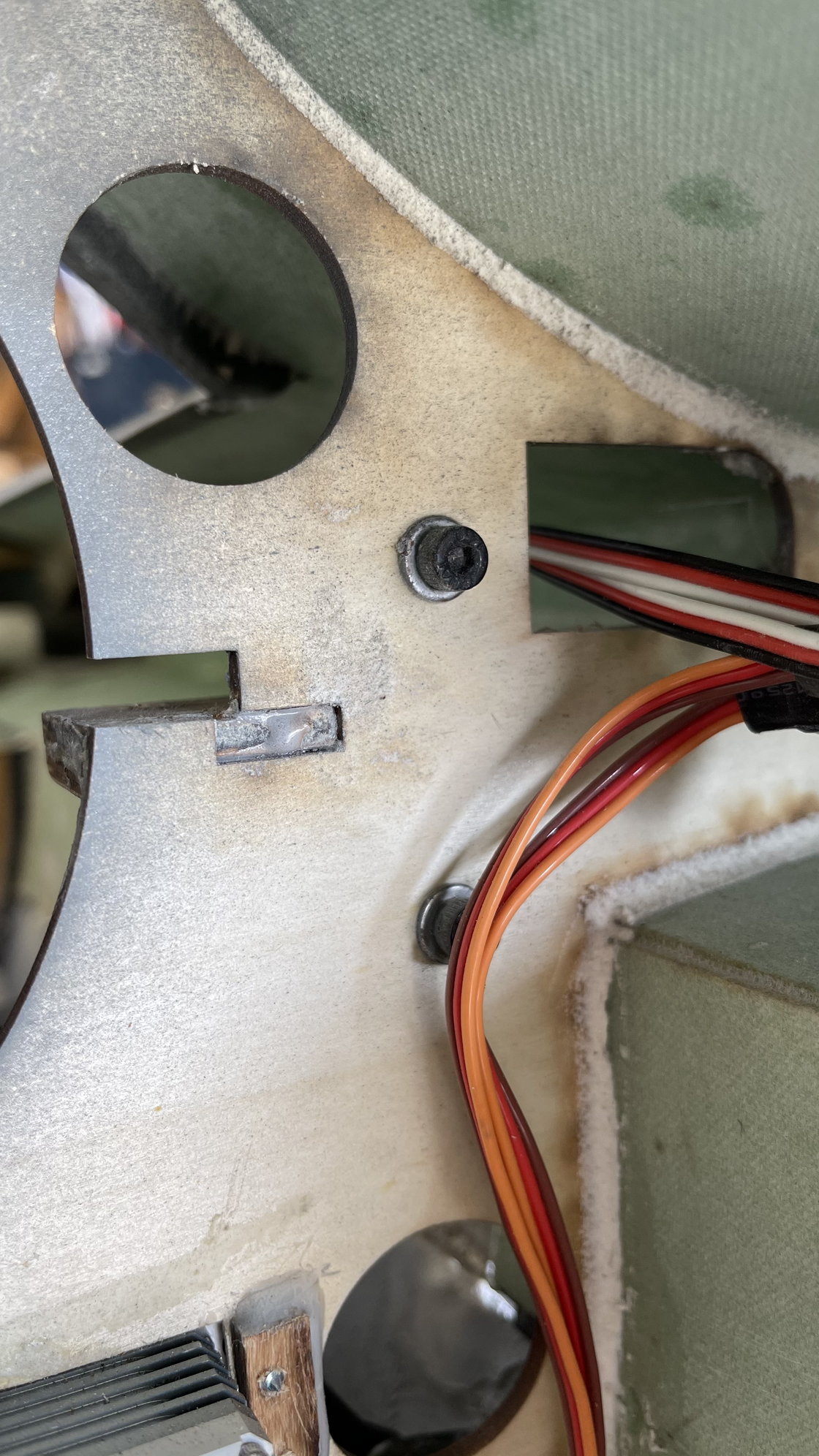
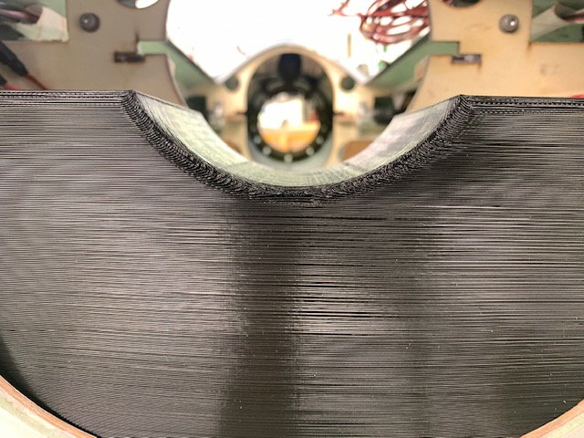
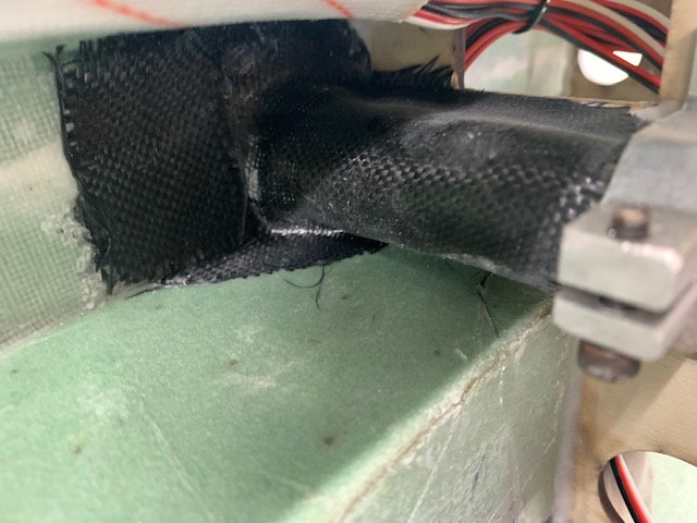
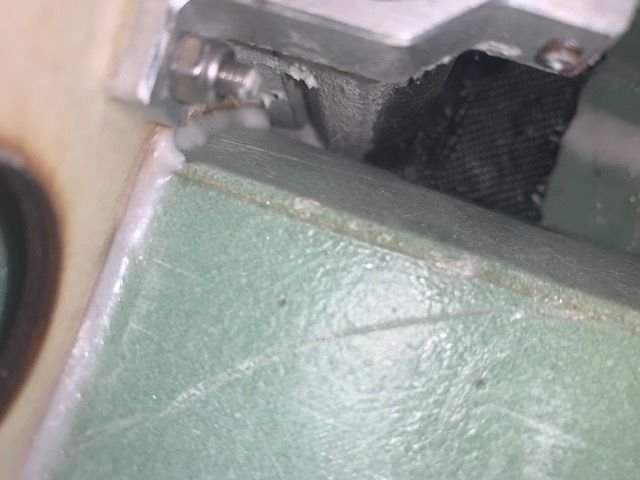
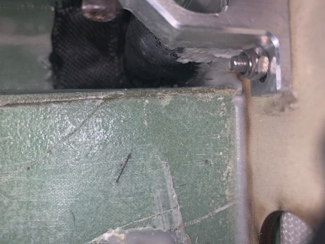
Here is the rear wing tube former at the rear of the turbine hatch viewed from the rear. You can see where the wing tube clamps are bolted to the former. In front of the former the tube and clamp are glued to the former and overlaid with some CF cloth. There appears to be about an 8mm plywood spacer strip between the fiberglass wing tube sleeve and the face of the former. It is glued to the former and there is some space between it and the fiberglass sleeve. Its hard to see except from the bottom of the wing tube sleeve.
There is no CF cloth on the back side of the former. The bond of the fiberglass tube sleeve to the former depends entirely on the quality of the joint between the spacer, the sleeve, and the face of the plywood. In the one I can see there is no glue there and the CF cloth does not wrap under the sleeve to the former so it is only secured by the CF wrap over the top which stops at the rectangular hole. To some degree the composite structure of the fuse around the former joint will help but there is nothing else on the outside edge of the former holding the tube in place except for the CF wrap. So there is not much supporting the outer end of the with tube sleeve.

The former is 3mm china 5 ply so the bond between the outside ply and the rest of the plywood is what is holding the tube to the former and spreading the load to the former.
Front left tube clamp view from turbine bay looking forward. All the CF cloth is on rear side of the former.
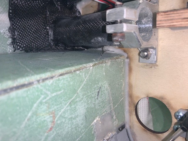
Bottom of front left tube clamp viewed from turbine bay looking forward. The CF wrap does not go to the former on the bottom of the sleeve.
Front left tube former view from front of former looking to left. There is no CF cloth on the front side of the tube joint or overlapping through the rectangular hole.

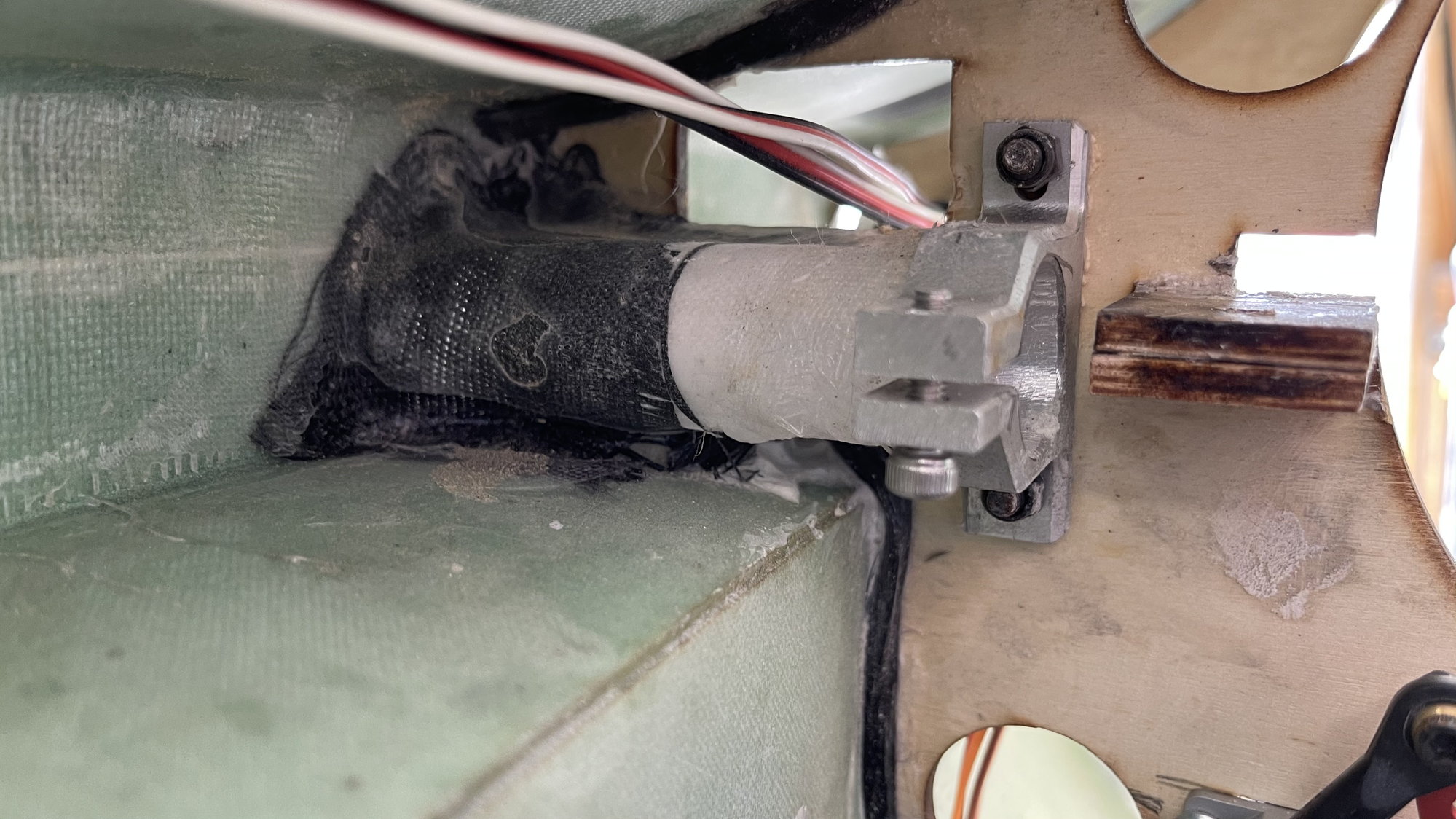
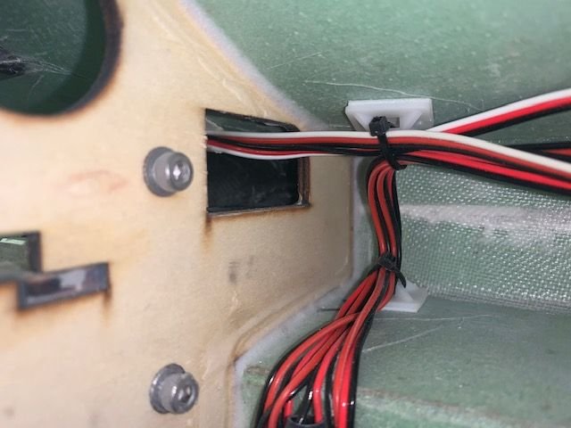
Aft left wing tube viewed from front of former looking left from inside turbine bay. All the CF cloth is on the front side of the former. No overlap thru the rectangular hole.

Aft left wing tube former view from just behind the former looking left from the pipe hole. No CF cloth on aft side of former.
Last edited by Viper1GJ; 03-27-2021 at 11:28 AM.
03-27-2021, 11:59 AM
#38
Thread Starter
My Feedback: (20)
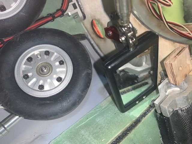
Inspection mirror under the wing clamps.
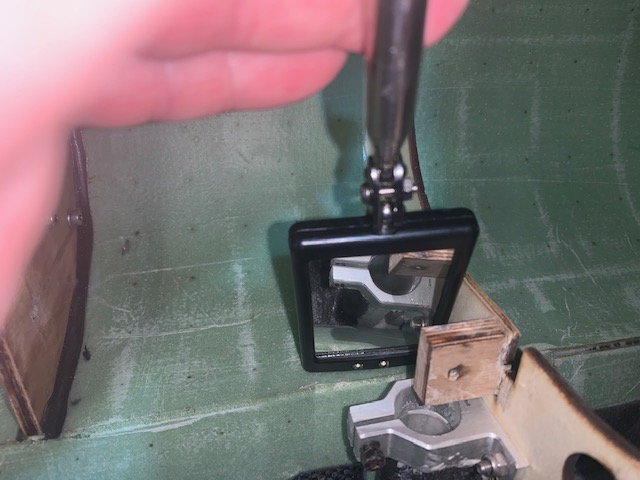
Left rear tube. This one needs to hold lots of the load. No epoxy between spacer and sleeve.
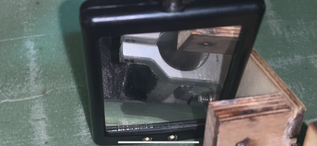
Left rear blown up. You can see the gap between the sleeve and the spacer. the bolt and nut are on the wing tube clamp surface
Right front
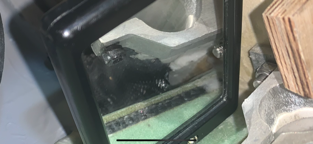
Right front same problem but the CF is wrapped under it a little better but it does not contact the wood.
Right front again.
Left front
Even though my flying style mostly is smooth with slower high AOA stuff, I will feel better with beefing up the wing tube joints. After inspecting the bottom of the wing tube joints, I am thinking abonut making a simple mod that will help a little. I will inject Six10 epoxy as much as possible between the sleeves and the spacer to fill the gap and then wrap some CF cloth (fiberglass if the CF will not lay down ok) from underneath the sleeves to over the top and through the rectangular hole and down the other side of the formers. I may try laying in some CF tow in the lower corners of the formers if I can get to it. This will make sure the other side of the former is tied to the wing tube sleeve. Suggestions appreciated.
Thanks
Gary
Left rear tube. This one needs to hold lots of the load. No epoxy between spacer and sleeve.
Left rear blown up. You can see the gap between the sleeve and the spacer. the bolt and nut are on the wing tube clamp surface
Right front
Right front same problem but the CF is wrapped under it a little better but it does not contact the wood.
Right front again.
Left front
Even though my flying style mostly is smooth with slower high AOA stuff, I will feel better with beefing up the wing tube joints. After inspecting the bottom of the wing tube joints, I am thinking abonut making a simple mod that will help a little. I will inject Six10 epoxy as much as possible between the sleeves and the spacer to fill the gap and then wrap some CF cloth (fiberglass if the CF will not lay down ok) from underneath the sleeves to over the top and through the rectangular hole and down the other side of the formers. I may try laying in some CF tow in the lower corners of the formers if I can get to it. This will make sure the other side of the former is tied to the wing tube sleeve. Suggestions appreciated.
Thanks
Gary
 03-27-2021, 02:35 PM
#41
My Feedback: (2)
Some videos from today, I beef up the wing tube joints but we had no issues today, I assume over time it could be another story, especially with full throttle flybys but I won't be doing that with this jet, that said the F-16XL very predicable, smooth, no surprises, I can fly extremely slow I flew Josh's XL today for a little bit and felt like most delta wing jet's I've flown. Takeoff's and landings are a non event. I think on the 3rd flight Josh flew for 7mins and the 2 main fuel tanks were 95% empty and still had another 30oz header tank and UAT completely full. 40-50% throttle for most of the flight with a 2 full power verticals. No CG corrections needed. Overall we are pleased, I think once the wing tube joints are beefed up and minor improvements it will be a great jet, it has a great presence in the air that's for sure. 50 degree temps with a slight quarter 5-7mph wind. I look forward to flying my XL hopefully very soon.
Last edited by F900; 03-27-2021 at 02:48 PM.
The following users liked this post:
Viper1GJ (03-27-2021)

The following users liked this post:
yeahbaby (03-27-2021)
03-27-2021, 03:26 PM
#44
Thread Starter
My Feedback: (20)
I really don't think any parts would be of use. It's just the wing tube sleeves need to be firmly secured to the formers. Mine seem to have some gaps when viewed from the bottom. I think I can fill and patch with epoxy and CF cloth or the Kevlar cord as mentioned above and it will be fine. I would recommend a more secure system in future production.
The thing I need quickly would be a decal set for the fuse so I can repaint the cream color to grey. I'm really looking forward to flying the XL. Looks like it will be a great jet!
Thanks for keeping in touch and for your help,
Gary
03-27-2021, 03:34 PM
#45
Thread Starter
My Feedback: (20)
Fuel tank tubes
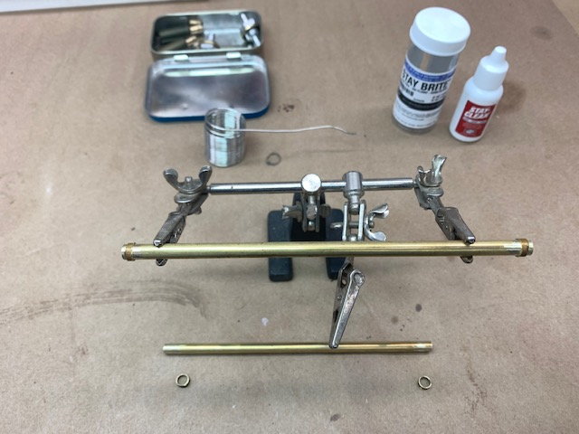
Soldered some homemade barbs on to the 3/16" ID brass tubes
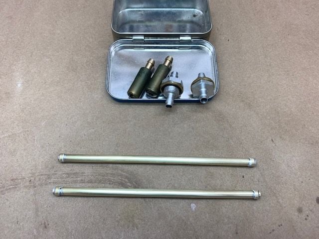
Ready to assemble
Tank parts laid out for Viton tubing measuremnets
3/16" ID VIton flexible tubing for the clunk lines
Clunks installed
Soldered some homemade barbs on to the 3/16" ID brass tubes
Ready to assemble
Tank parts laid out for Viton tubing measuremnets
3/16" ID VIton flexible tubing for the clunk lines
Clunks installed
03-27-2021, 03:50 PM
#47
Thread Starter
My Feedback: (20)
Discussed changes to the fuel tank today with Keith. It will be flat across the top. This will allow a Velcro hold down strap to go across the top and not interfere with air flow to the turbine. It will be 4mm less wide to better fit through the former. There will be a relief recess at the bottom to clear the bottom fuse bolt. Also it will be printed in two halves to allow for printing some internal structure to make the front and back sides stiffer. There will still be plenty of volume for fuel. Joshua says he only needed about 35 oz for reserve and this will still have more.
Last edited by Viper1GJ; 03-27-2021 at 04:07 PM.
03-27-2021, 05:44 PM
#48
My Feedback: (2)
Since I am using a 190 and the CG was right on I'm just going to use the same 32oz fuel tank, this should give me easy 7mins flight time, although I wish I has the skills your friend has for making custom fuel tanks. A smaller 32oz tank like your would be really nice. Happy to pay him if hes interested 
03-27-2021, 06:36 PM
#49
Gary,
Your inspection confirmed my suspicion based on your first post about the wing joiner. If that were me, I would not fly it without significant reinforcement at the outer end of the tube. As shown, I would class it as very unsafe.
Ideally the factory would install an outer 1/8" ply rib that was mechanically interlocked with the bulkheads which would also support the outer end of the wing joiner tube, thereby providing an outboard mechanical up/ down load-bearing capability to complement and react the wing bending loads against the existing inner clamp block.
As that cannot be easily retro fitted, maybe consider adding a hard-wood support block above and below the tube (full-length) that completely fills in the area between the tube and the upper and lower fuselage skins, and then glassing that in with additional carbon. Also, add another mini-bulkhead on the opposite side of the tube to the existing one to help tie the upper and lower fuselage skins together.
Paul
03-27-2021, 07:07 PM
#50
Paul ,
you are over thinking this wing mount. It's definitely Stronger then what you think. The carbon is puting the load into the airframe along with it being glued to the bulkhead. I put 3 flights on mine today and inspect them definitely no signs of stress and there was no wing flex in high g pulls. Saying it's unsafe to fly untill fixed is a bold statement with out seeing the jet in person.
you are over thinking this wing mount. It's definitely Stronger then what you think. The carbon is puting the load into the airframe along with it being glued to the bulkhead. I put 3 flights on mine today and inspect them definitely no signs of stress and there was no wing flex in high g pulls. Saying it's unsafe to fly untill fixed is a bold statement with out seeing the jet in person.

