


SIG Four-Star 60 Build
 04-24-2019, 04:01 AM
#126

Thread Starter
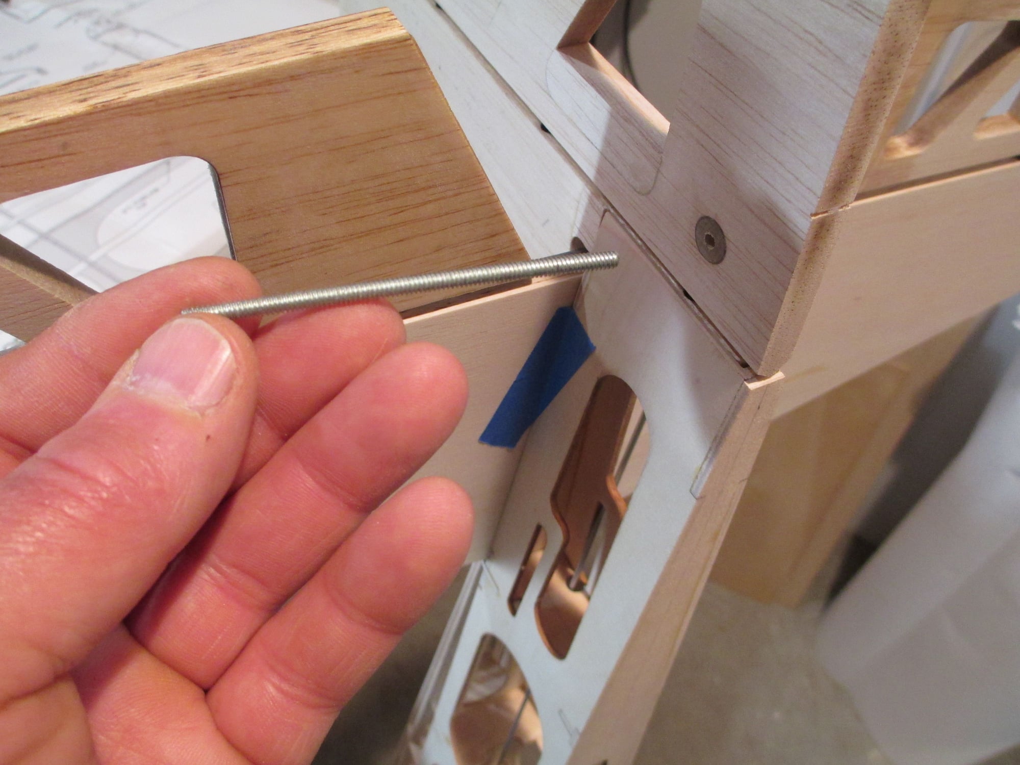
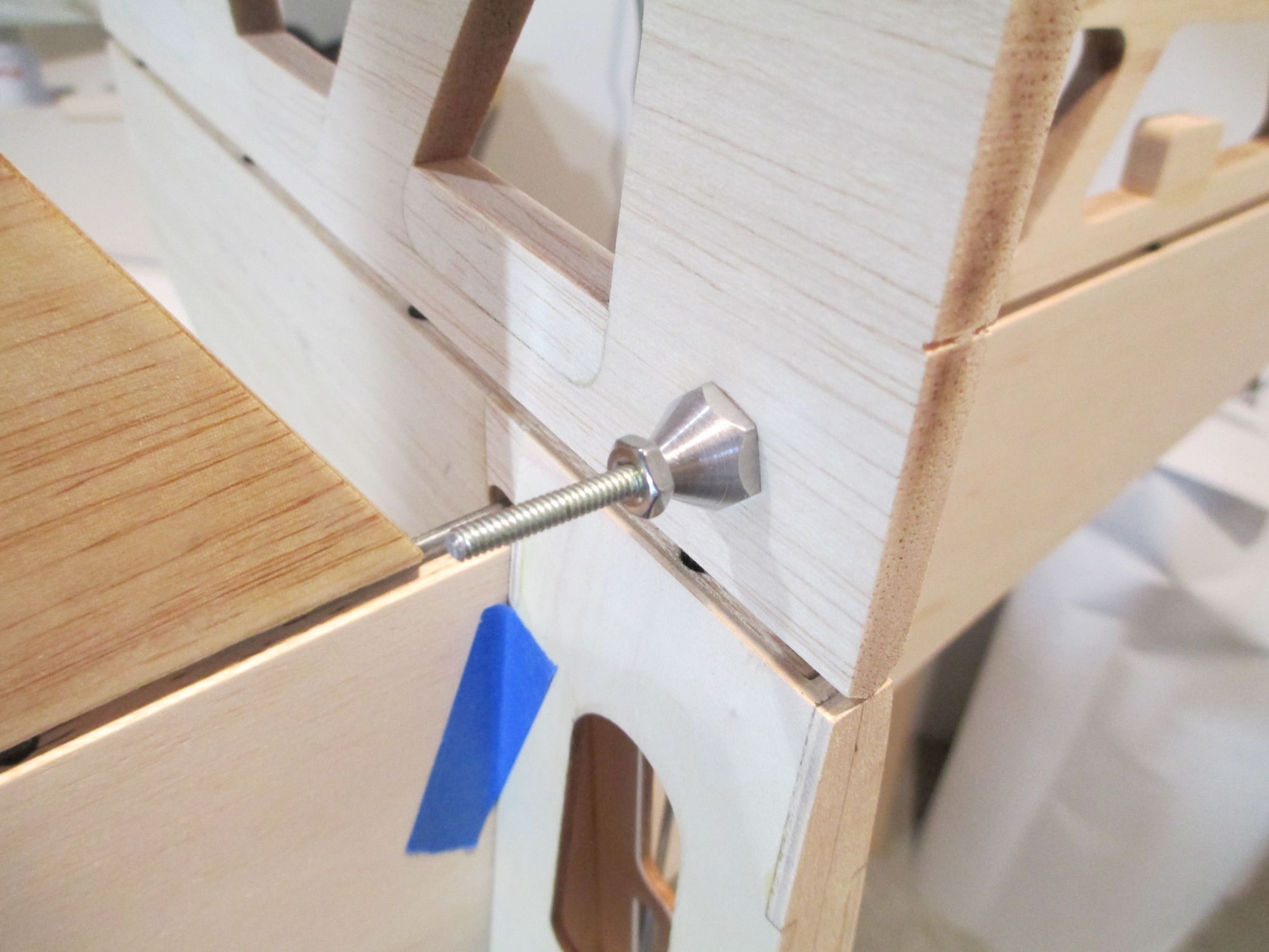
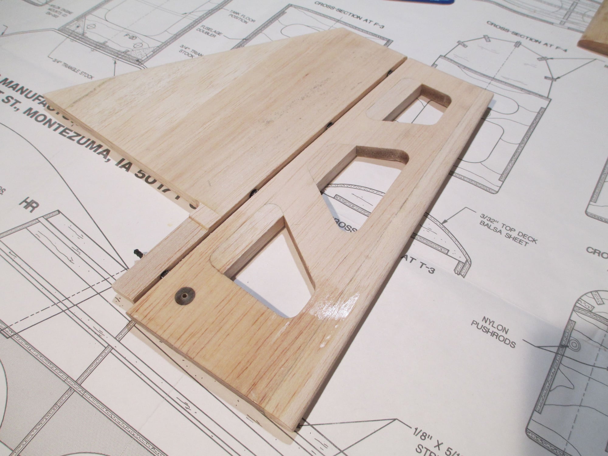
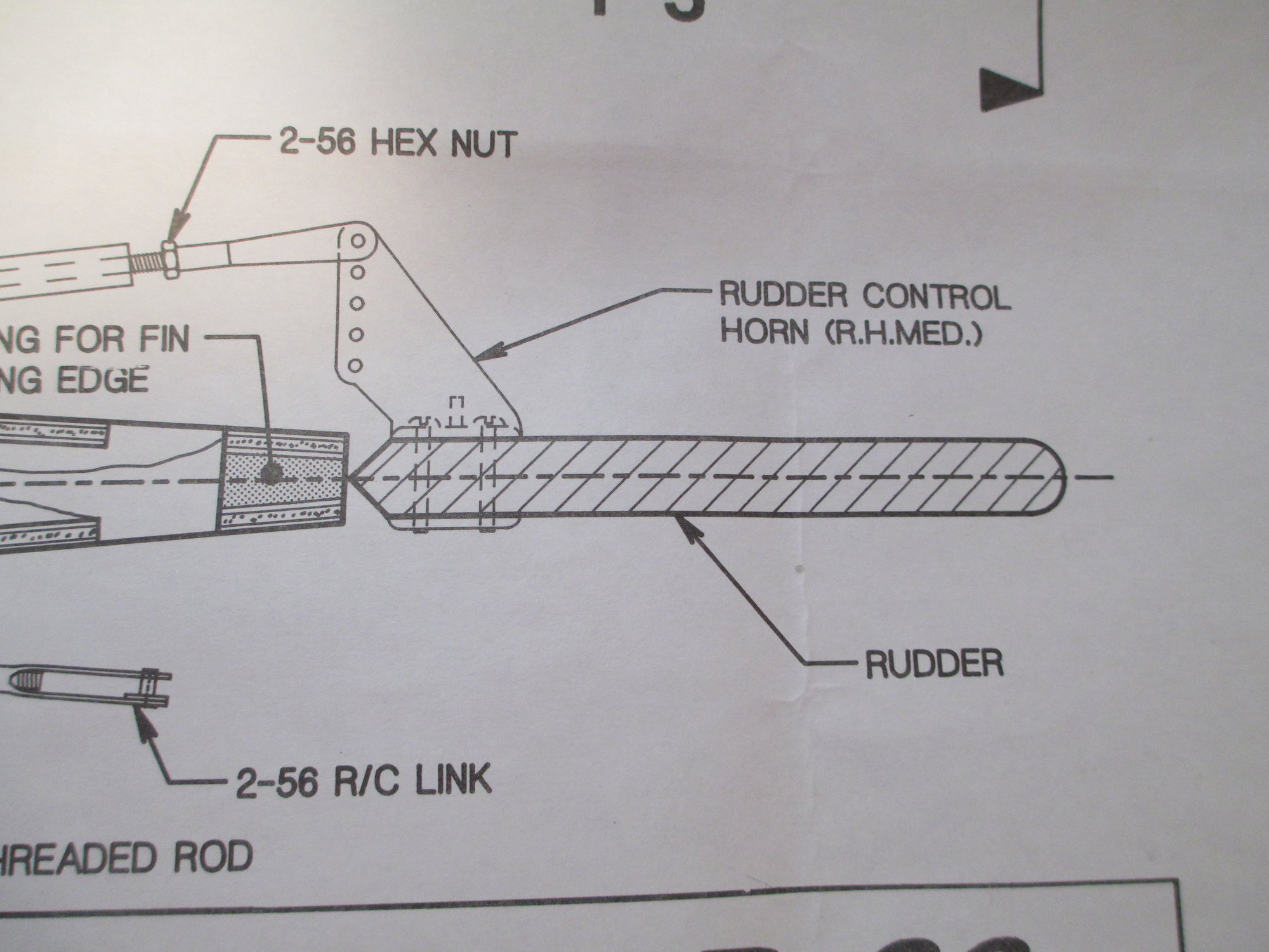
Time to get the pull-pull for the rudder completed. Notice the hard point is installed in the rudder, this will be the location of the horn. 6-32 threaded rod cut to length is inserted through the hard point...
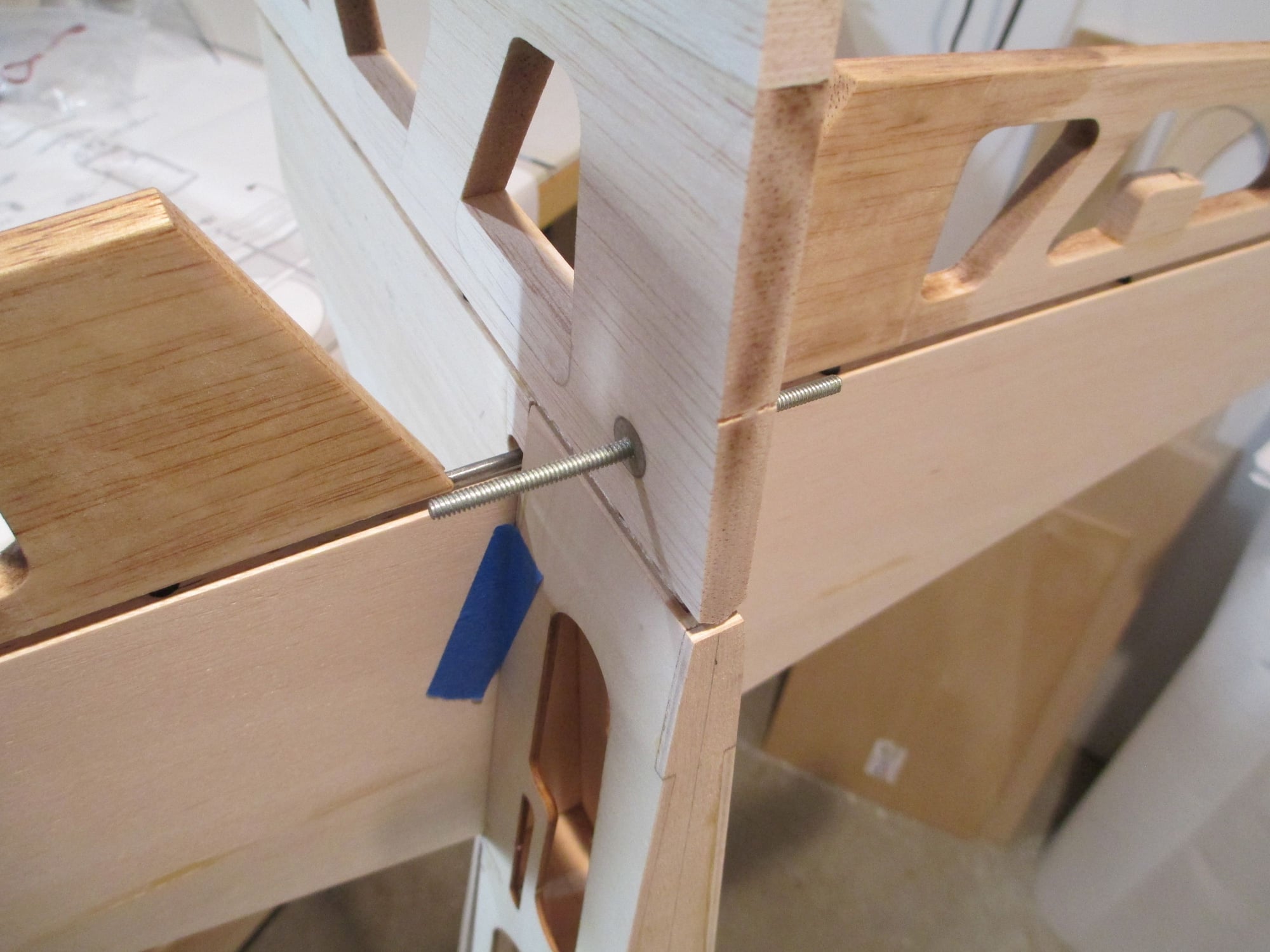
The threaded rod is centered.
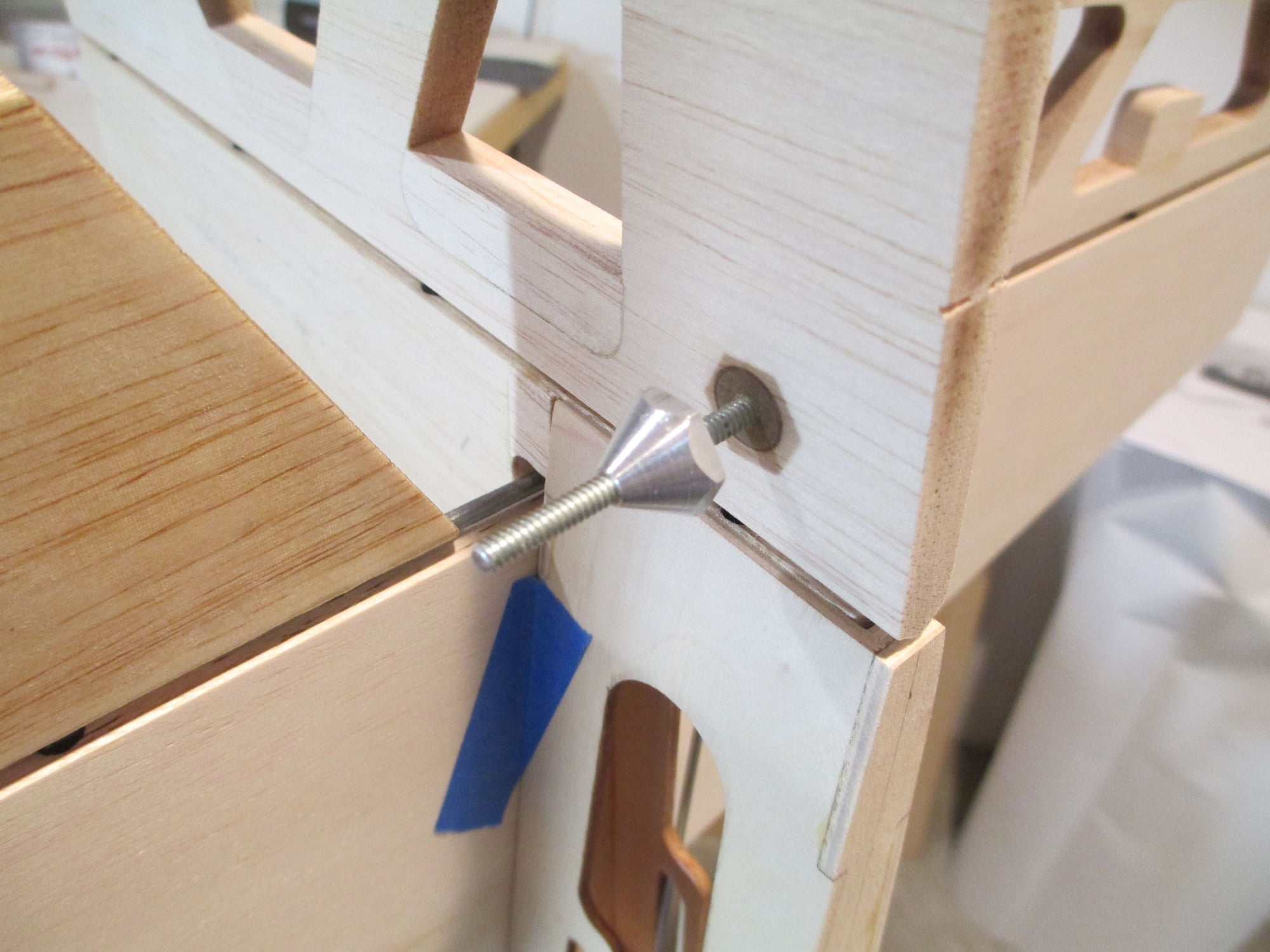
The conical nuts are then threaded on each end.
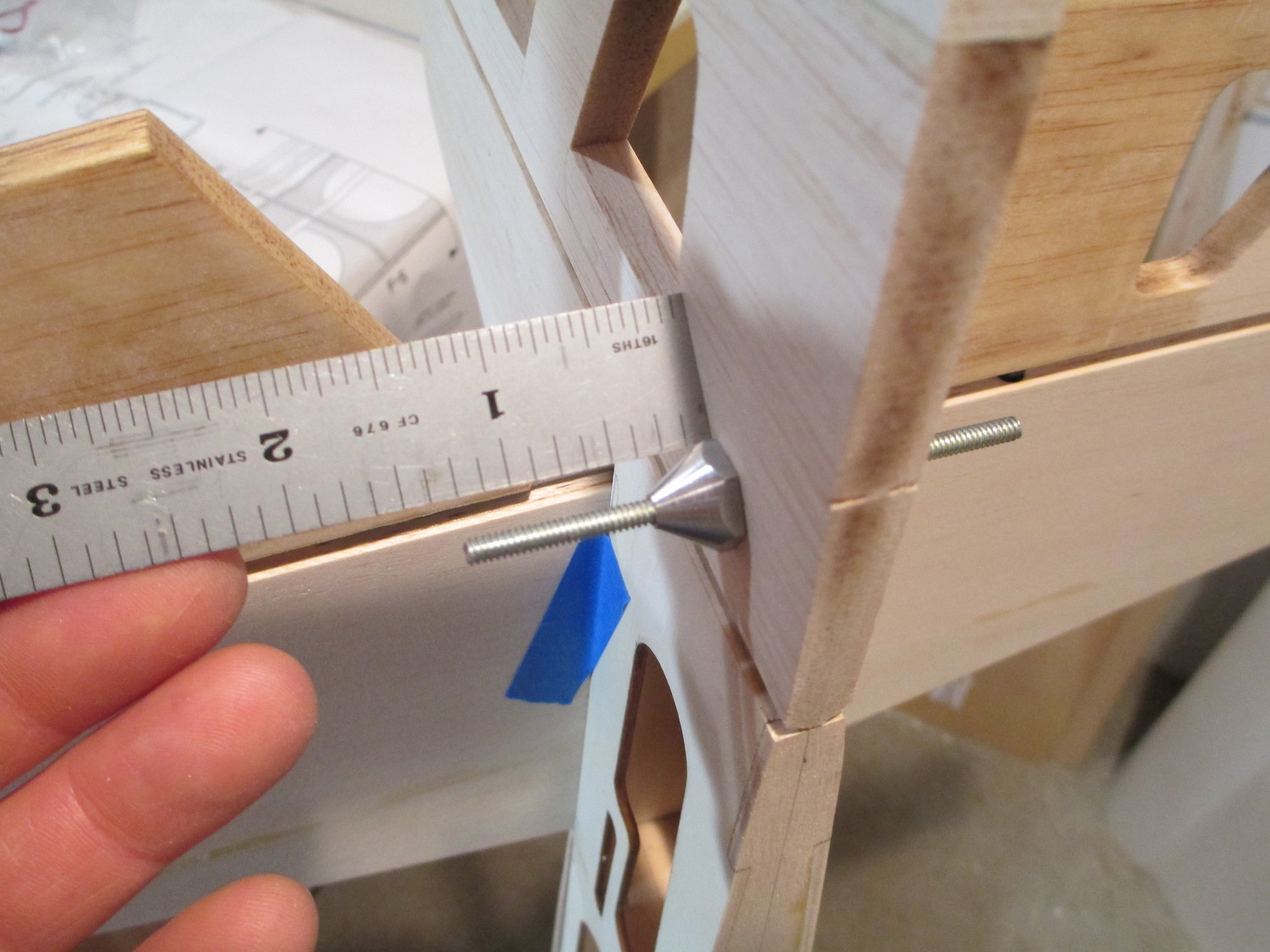
Just making sure that the length didn't move.
6-32 nuts are installed next, think of these as lock nuts ensuring the conical nut don't loosen.
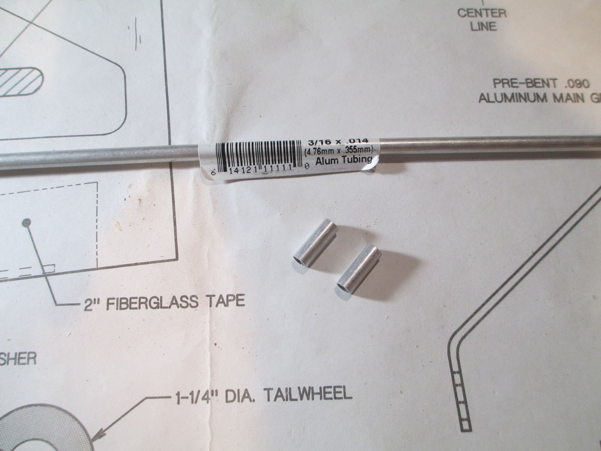
Not wanting to see the threaded rod exposed, I decided to cover them by slipping these cut off lengths of 3/16" aluminum tubing over the rods.
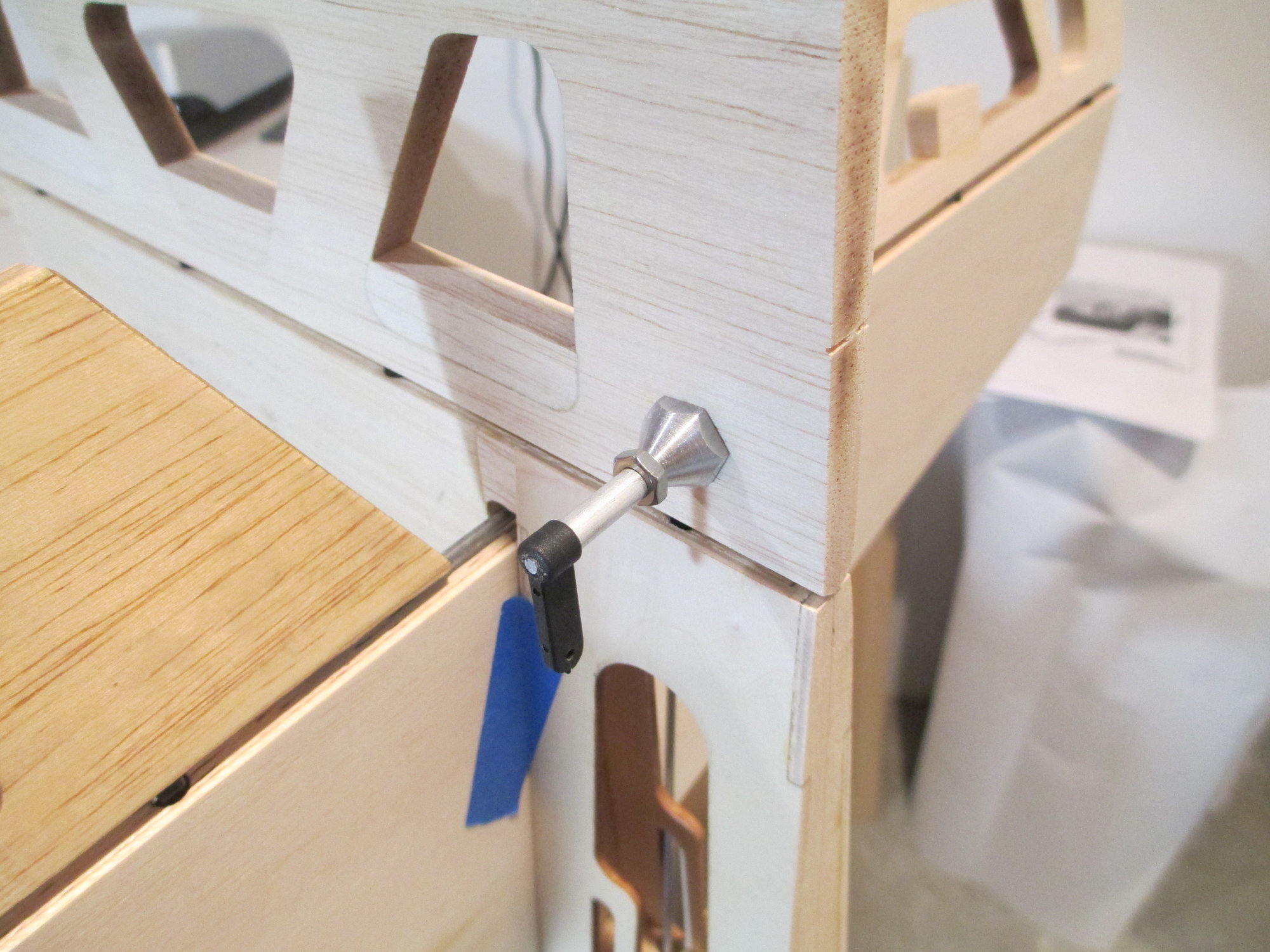
All that's left is to thread on the nylon horns...
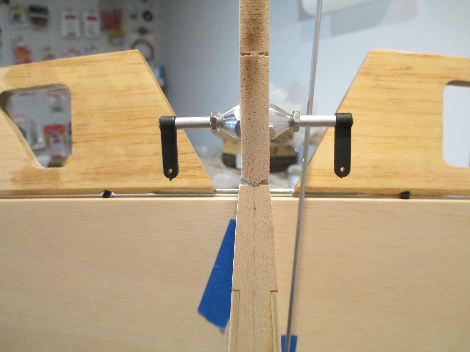
This is what it should look like completed.
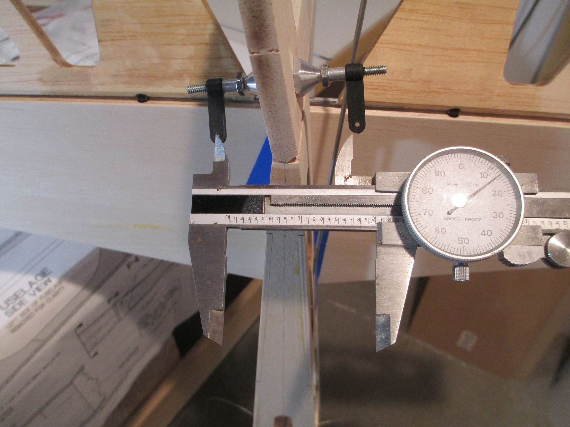
Just a few words on pull-pull wire geometry. In order to get the most efficient operating pull-pull set-up, the length of the horn spread and the bellcrank spread should be as close as possible. They (the bellcrank and horns) should make a perfect rectangle once the wires are installed. Of course there are other ways the pull-pull system can be set-up, but this is the best and most efficient way for this application.
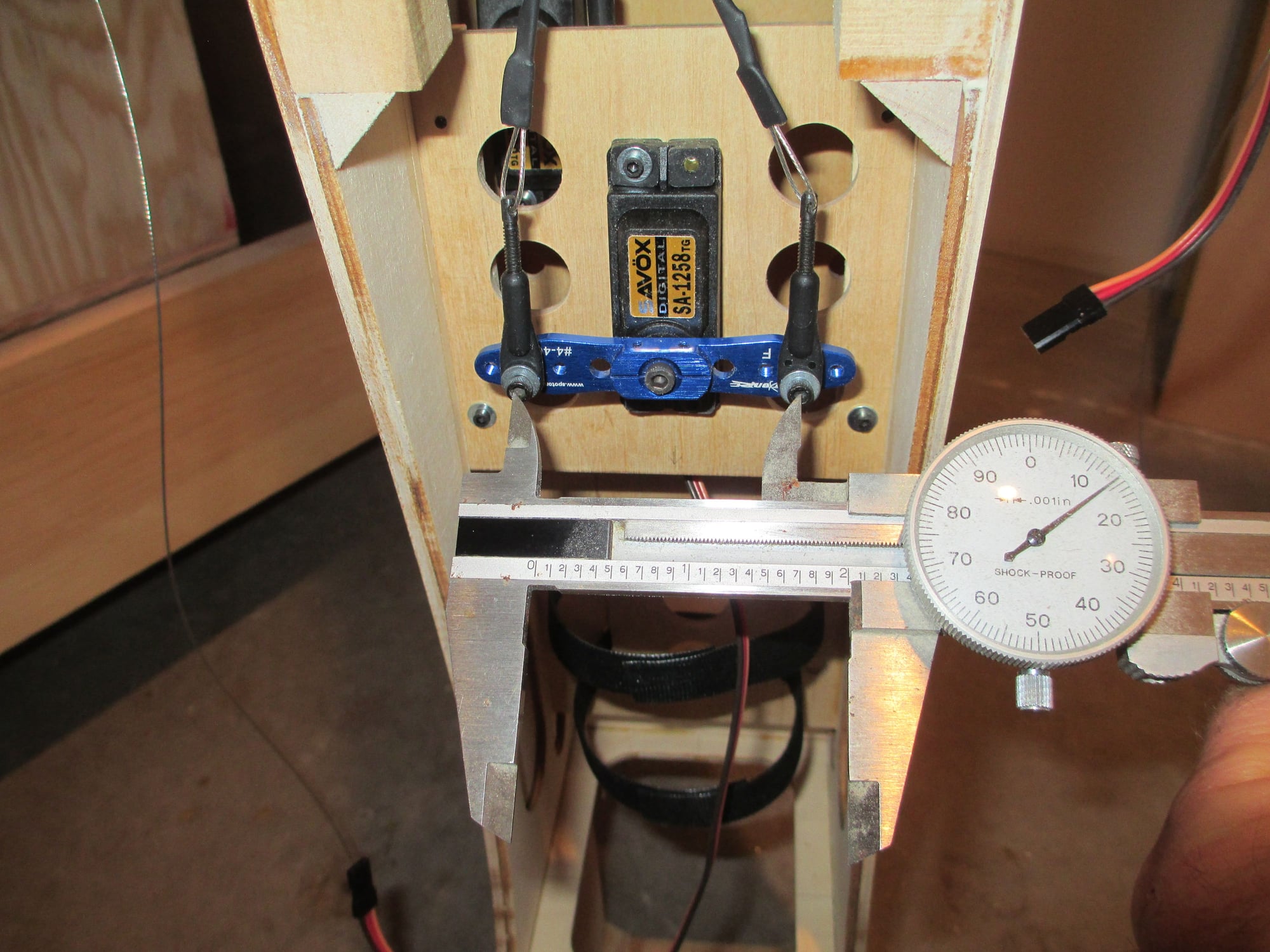
Checking the bellcrank spread.
 04-24-2019, 09:15 AM
#128
Thread Starter
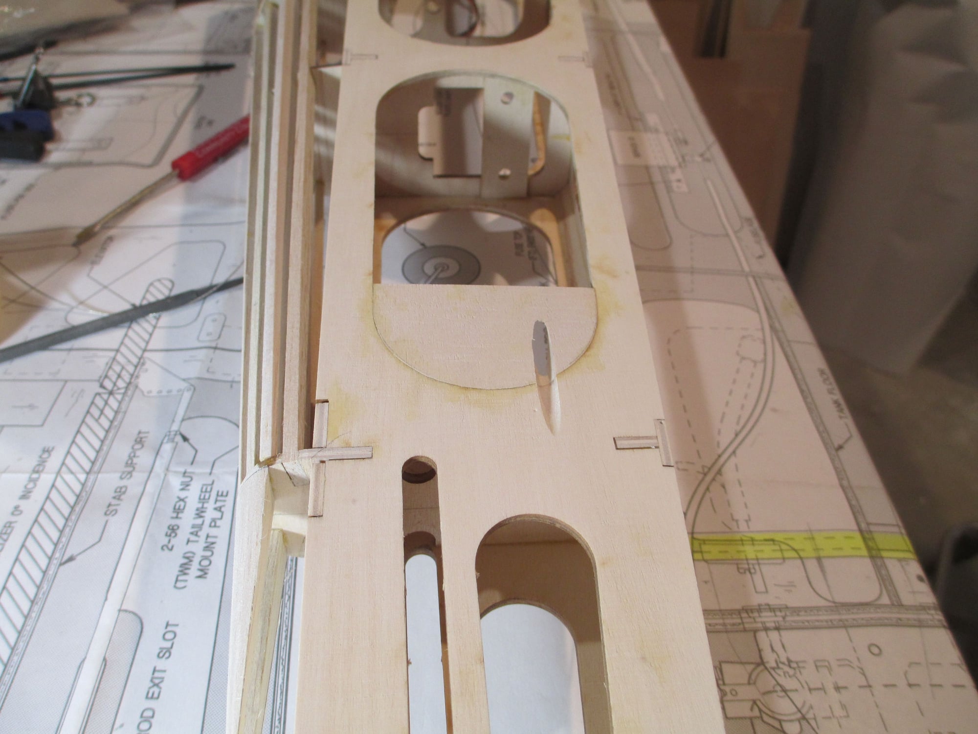
With the pull-pull wire exit locations located, I added a small bit of ply to anchor the exit tubes.
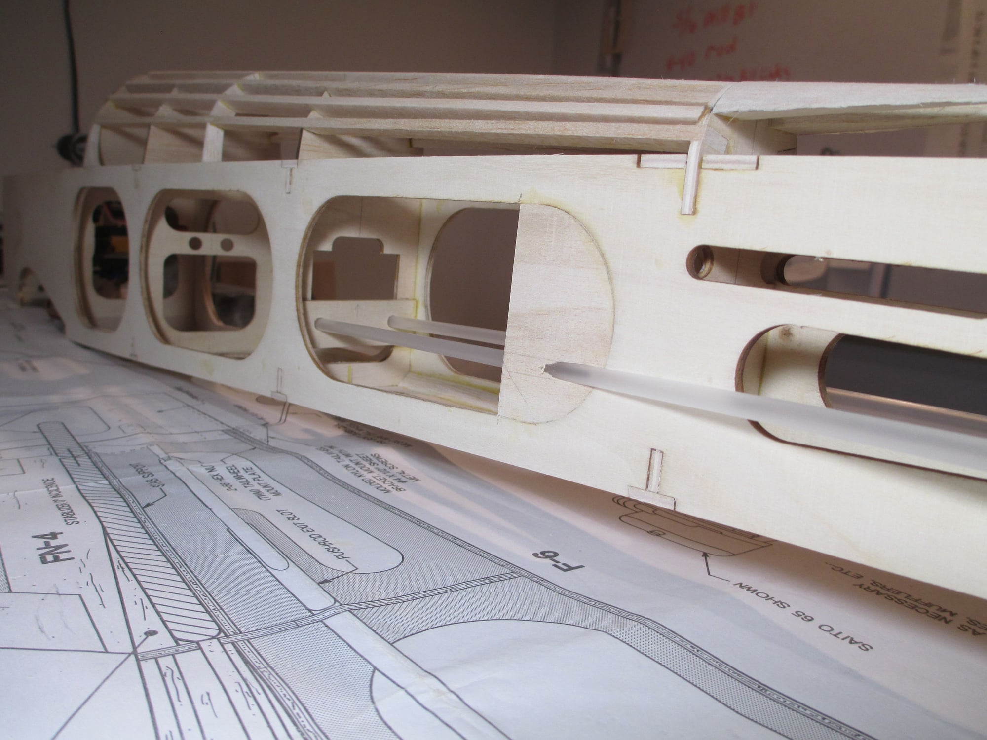
Plastic guide tubes were fitted and epoxied into place.
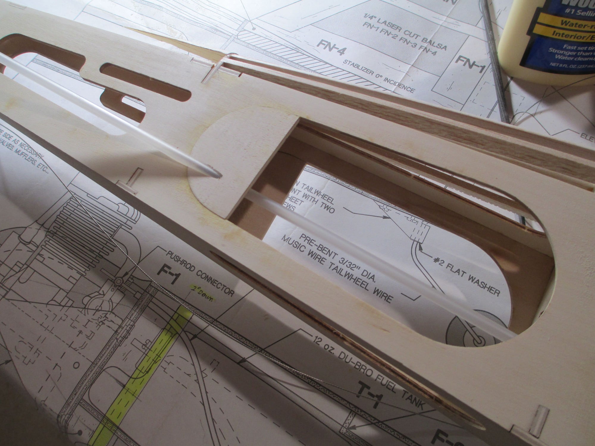
For now I let the tubes run proud from the sides of the fuselage, later they will be trimmed flush.
Last edited by VincentJ; 04-24-2019 at 09:18 AM.
04-25-2019, 03:10 PM
#129
Thread Starter
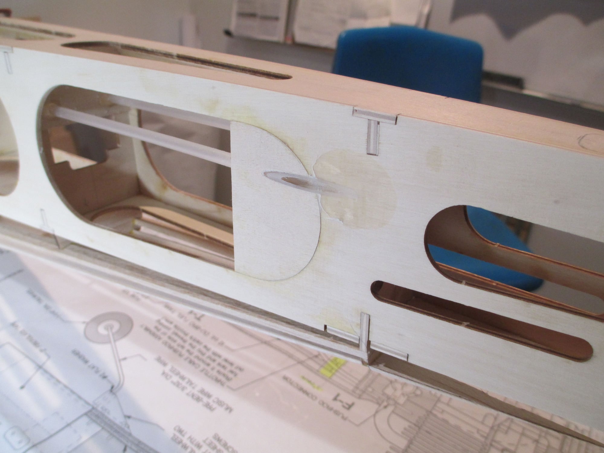
With the epoxy now cured, both nylon tubes were trimmed flush with the sides of the fuse.
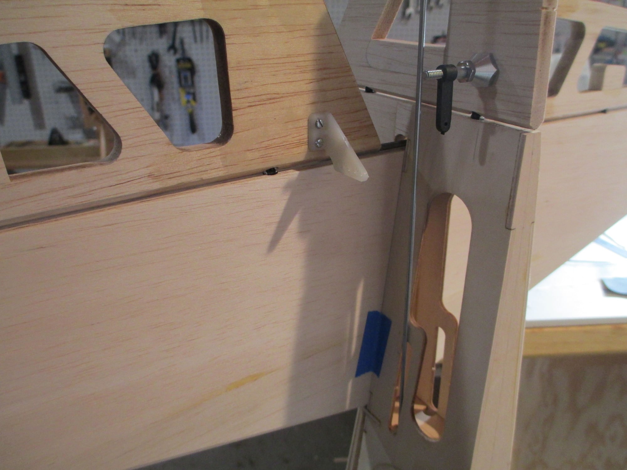
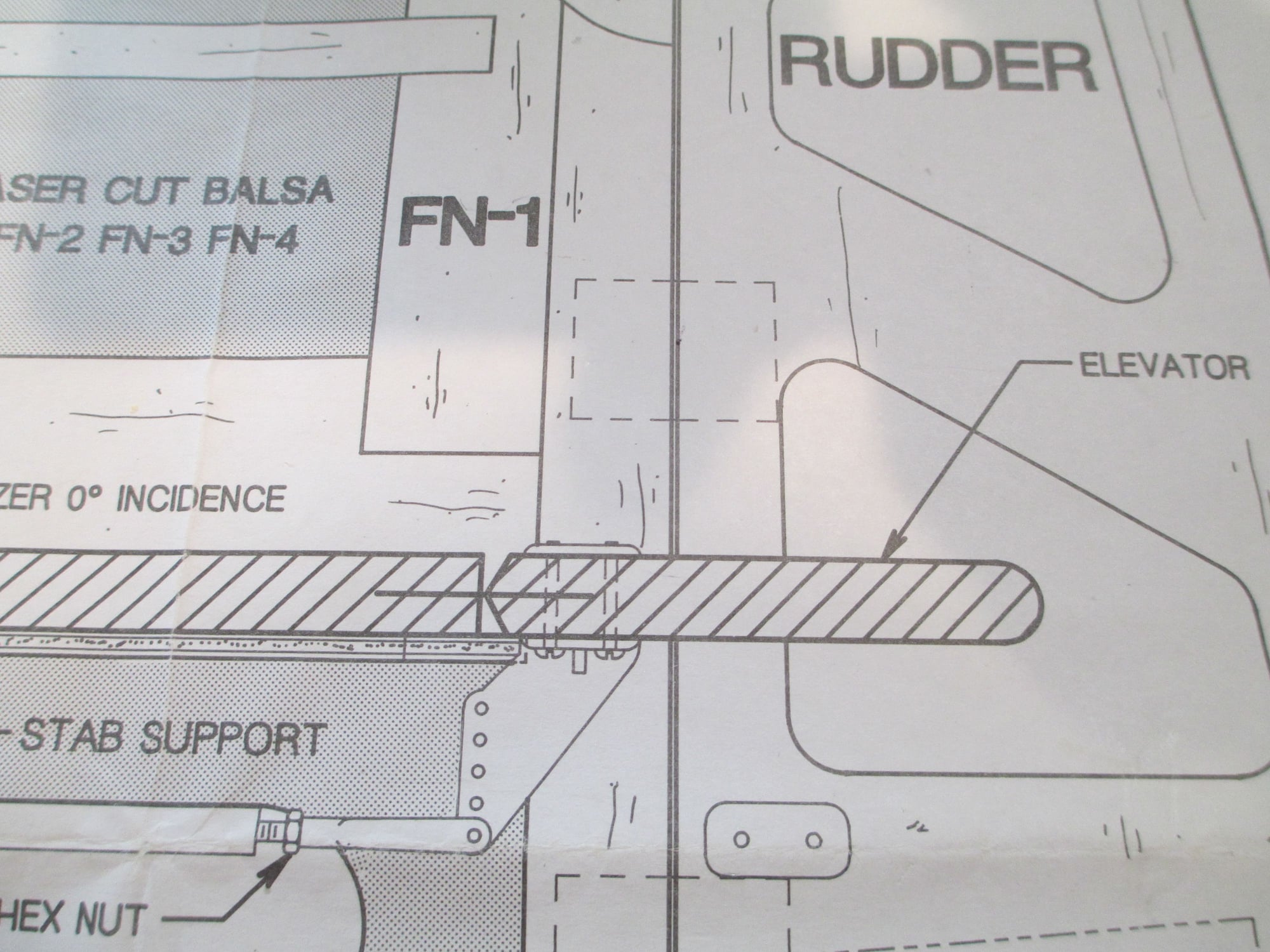
With the pull-pull set-up completed, time to get the elevator operational. I don't normally use this type of horn, but I was unable to use what I wanted because of the steel elevator joiner wire being smack in the place I needed to drill. So, after much deliberation, I decided on what you see here.
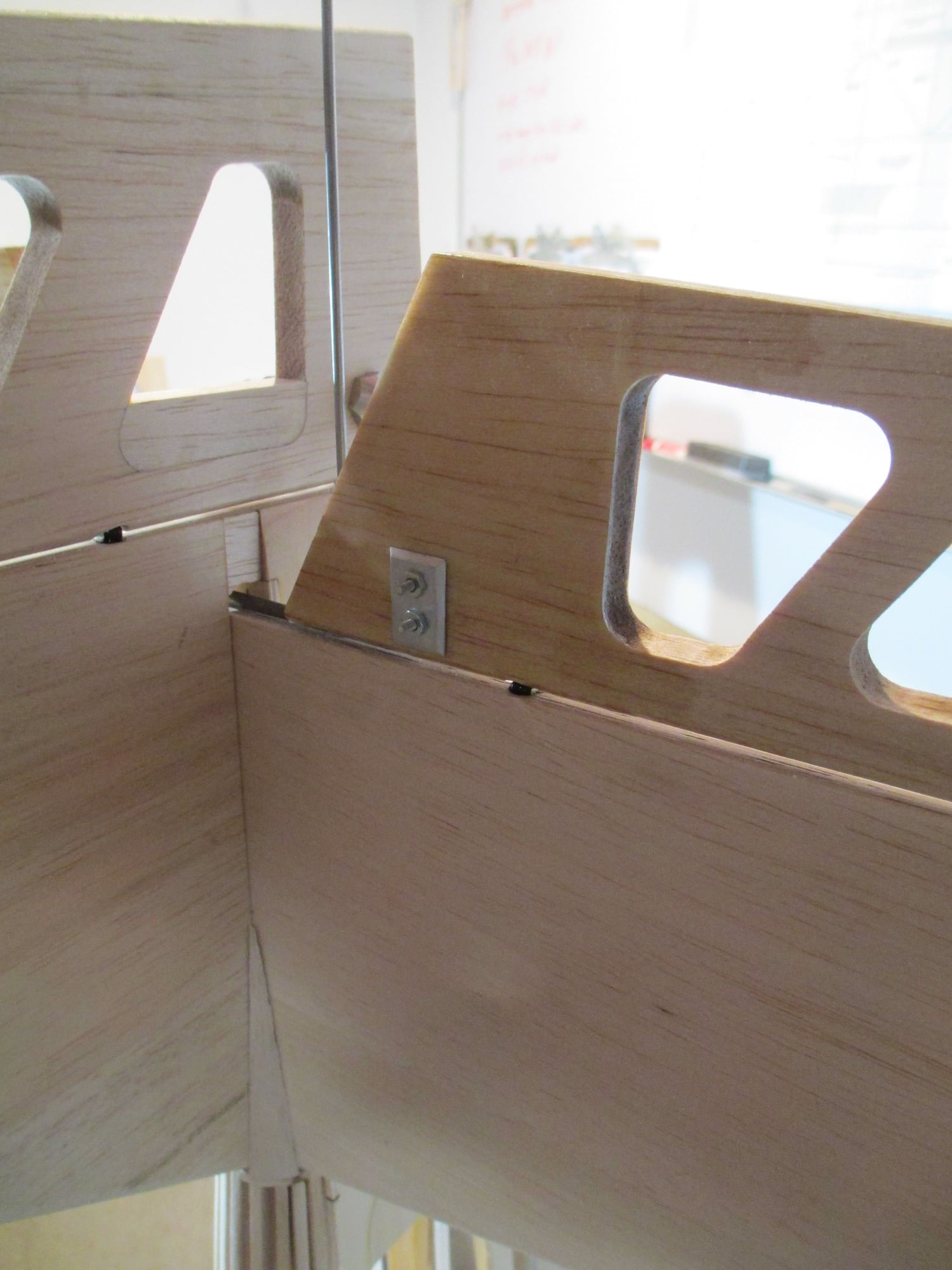
I made a custom plate to spread the load since I was unable to use a hard point. The area beneath the plate was glassed , so it should be fine. The 2-56 bolts will be shortened so they sit flush. If I get ambitious enough I may even make an aluminum horn to replace the nylon one...
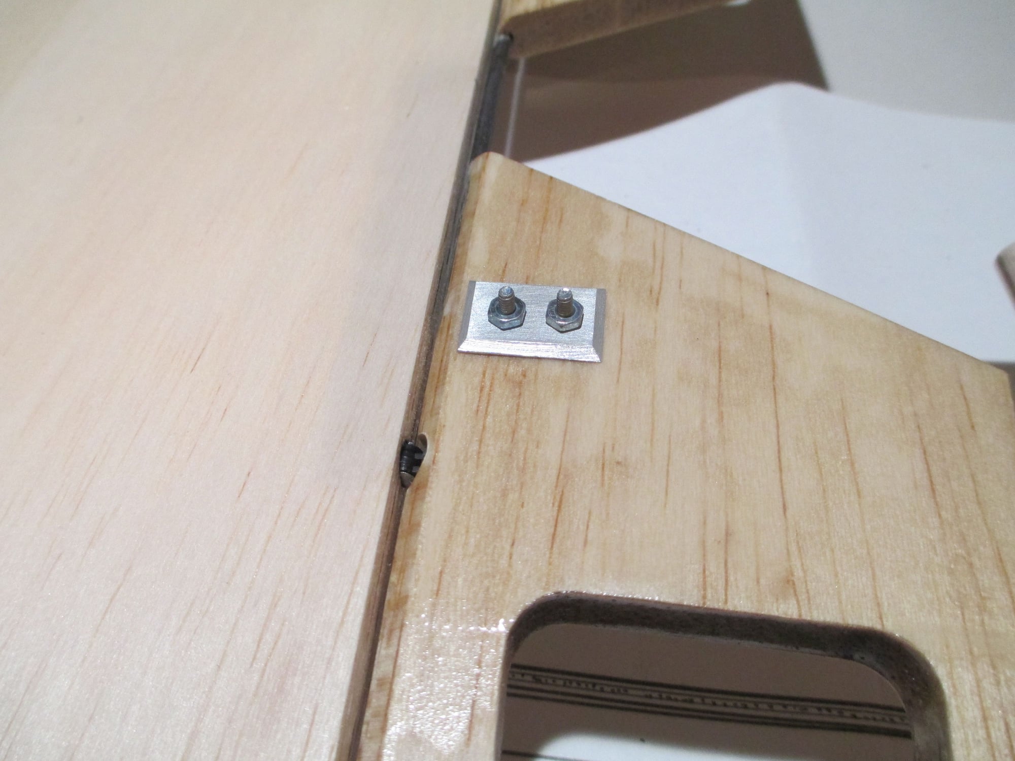
Close up of the plate. (It will get painted to match the covering)
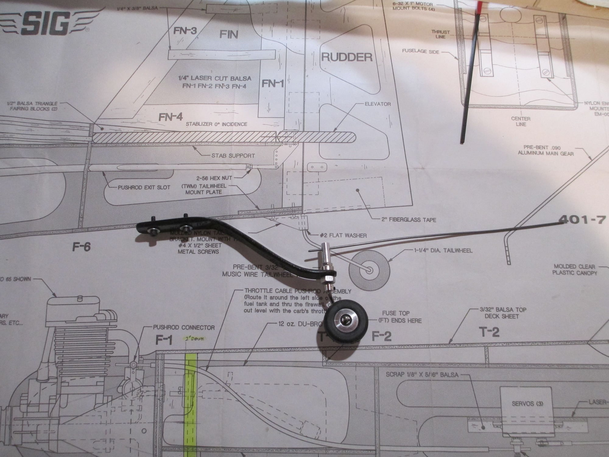
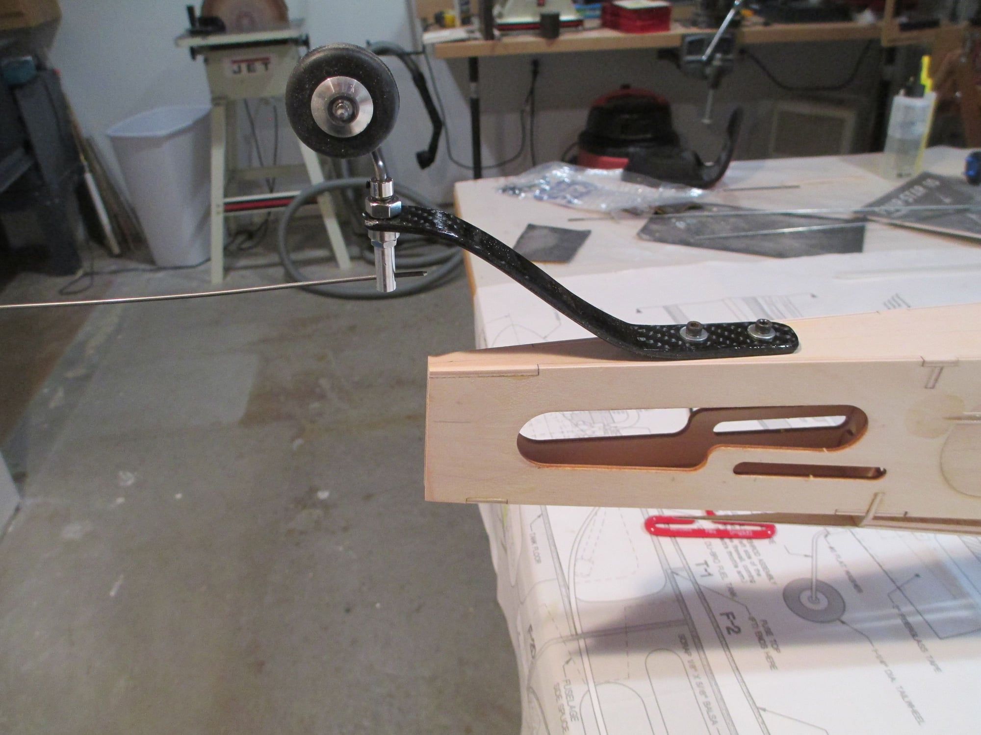
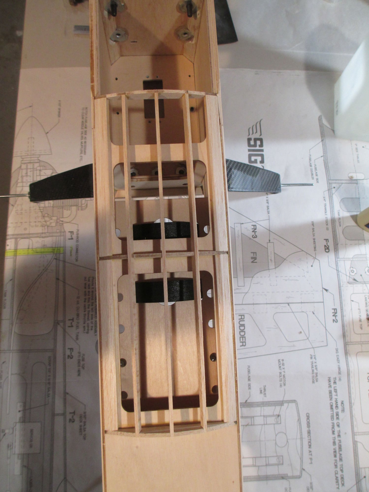
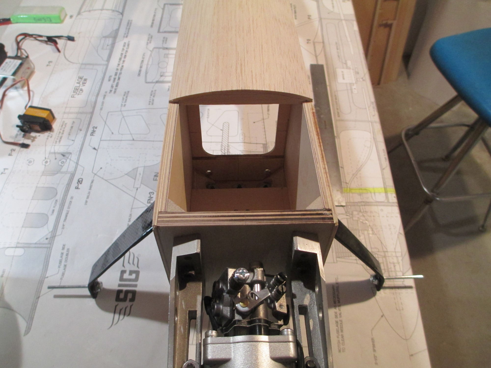
I decided on using a tiller bar to rotate the tail wheel. The tail wheel is 1-1/4", and the bracket is made from carbon fiber.
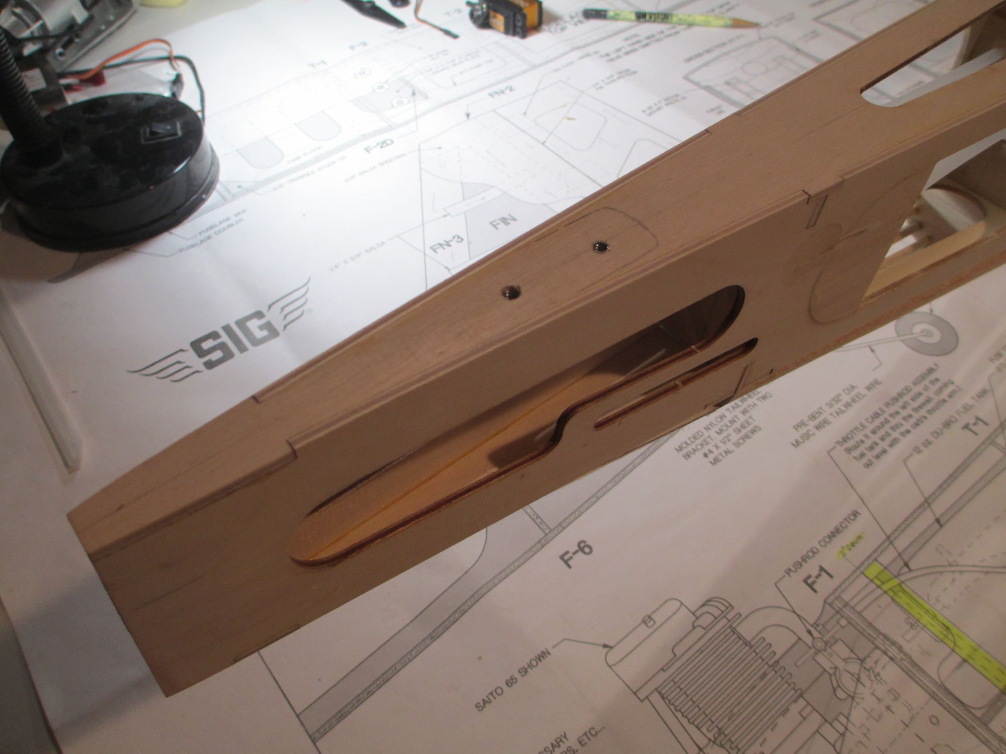
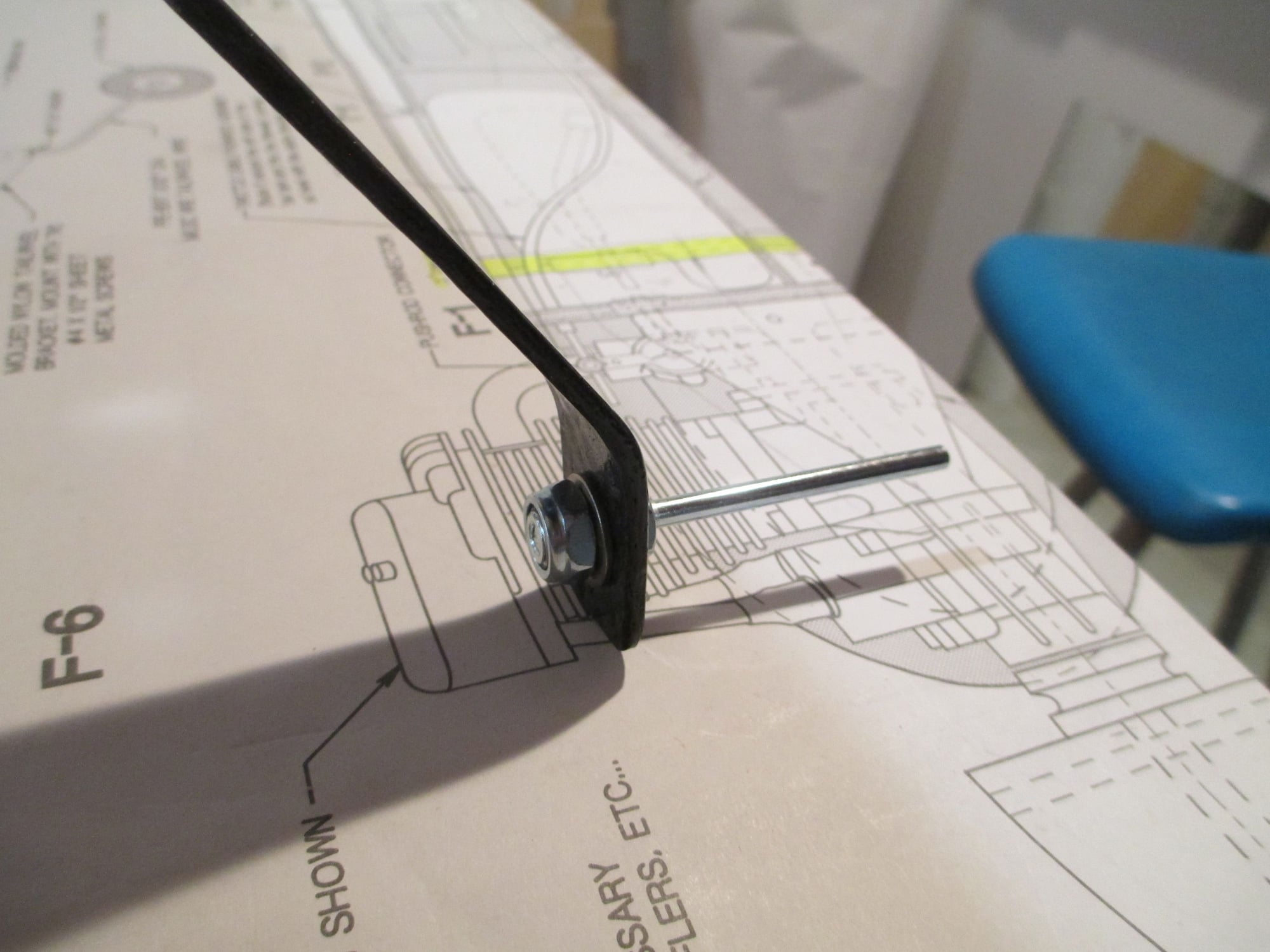
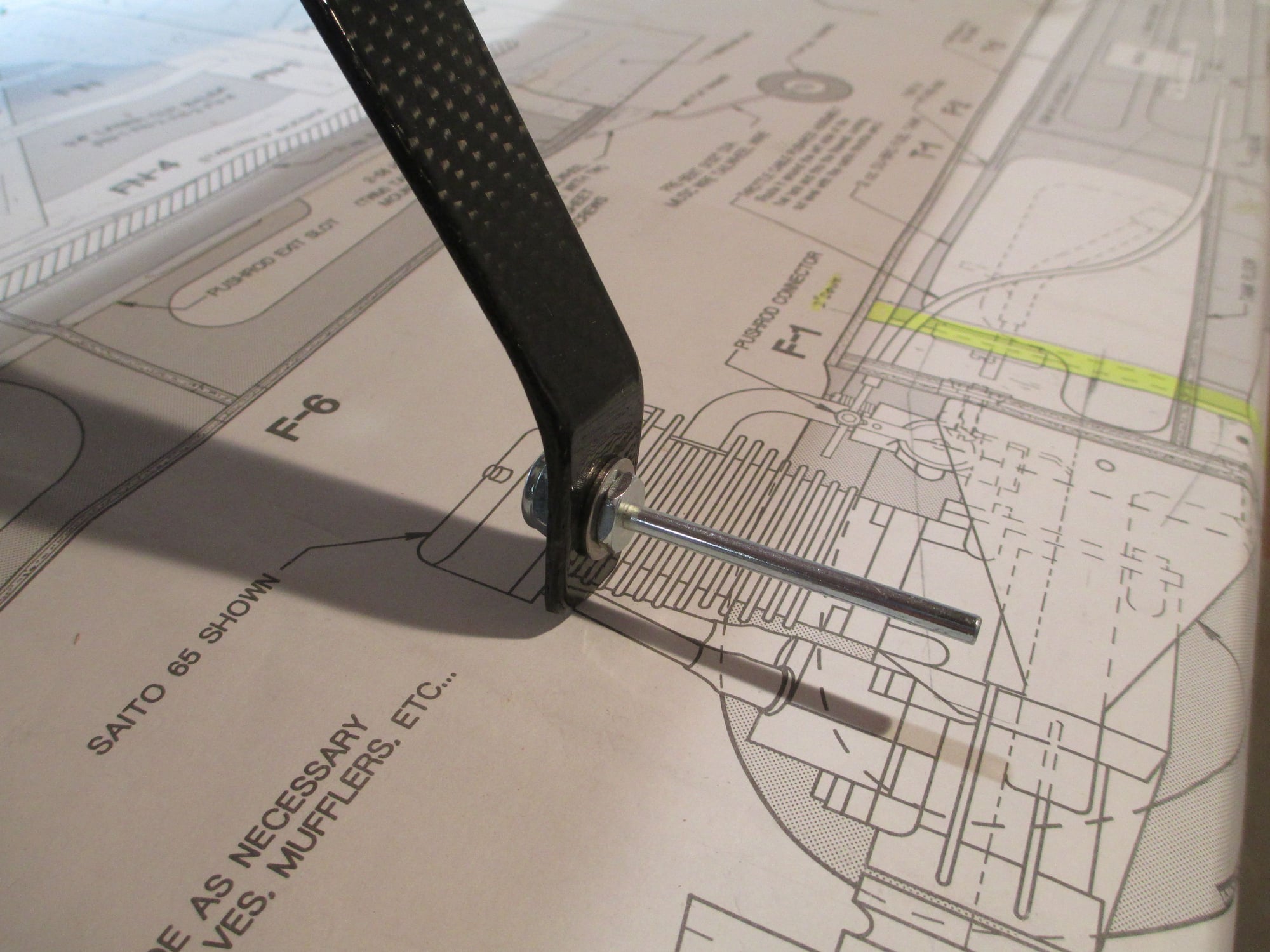
Since the bracket mounts farther back from the stock location, I made sure to reinforce the bottom with 1/8" birch ply. Two 6-32 cap head screws will secure the bracket in place.
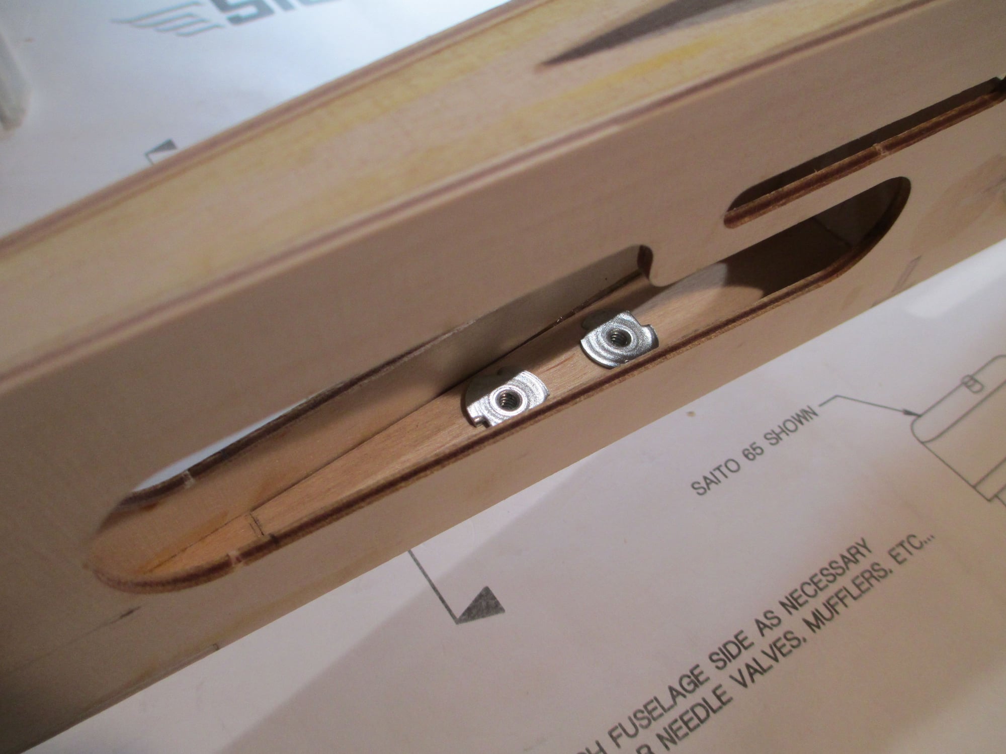
You can see in this shot the additional plywood added beneath the blind nuts.
Careful measurements were taken to ensure the tail wheel bracket is directly over the centerline of the fuse.
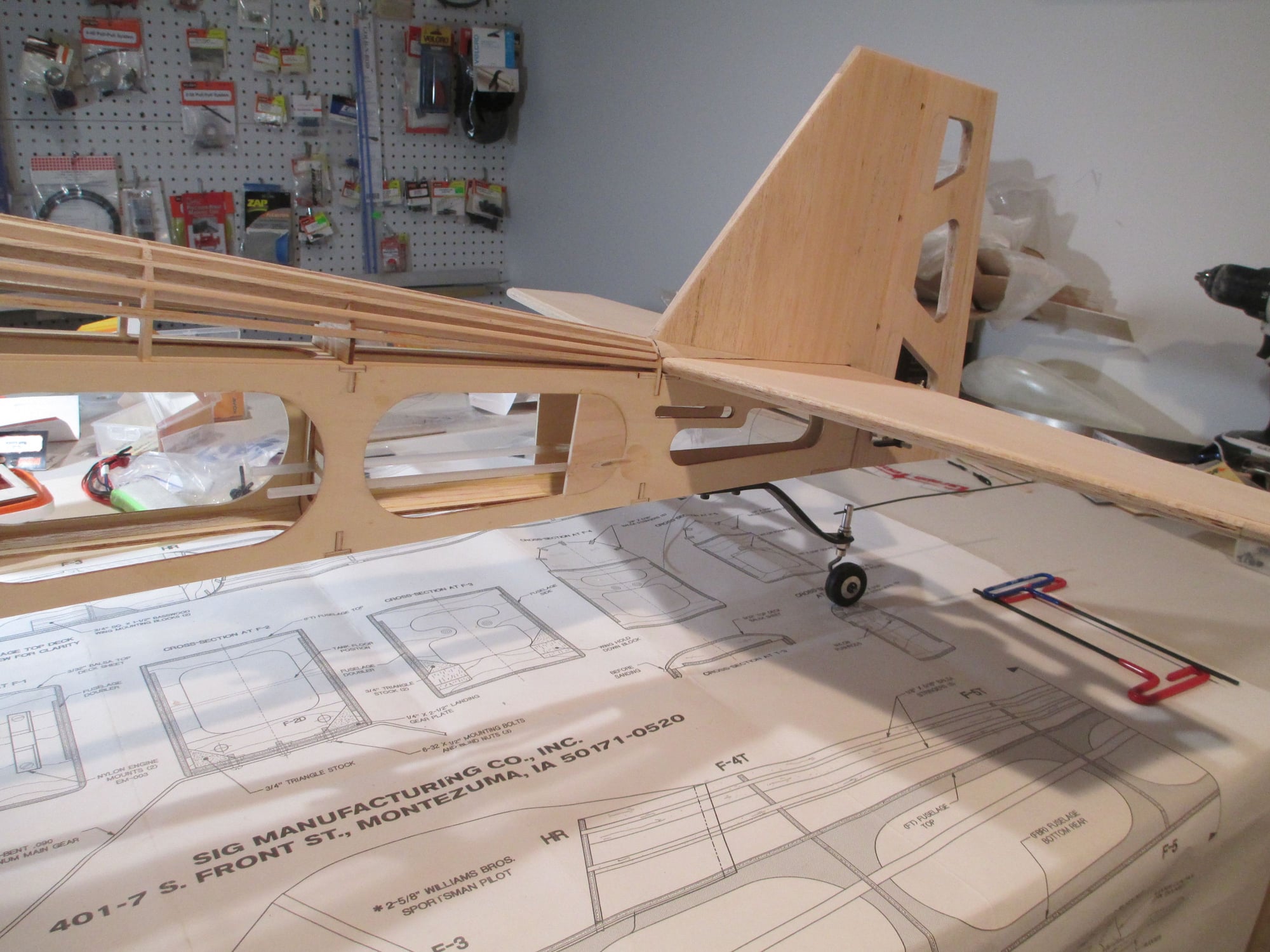
The tiller bar will be added later.
Axles were fitted to the CF landing gear.
Stainless washers were added on each side of the axle bolt to protect the CF. These axles will need to be shortened when I fit the wheel pants...another project to complete!
Last edited by VincentJ; 04-25-2019 at 03:18 PM.
04-26-2019, 03:13 AM
#130
Thread Starter
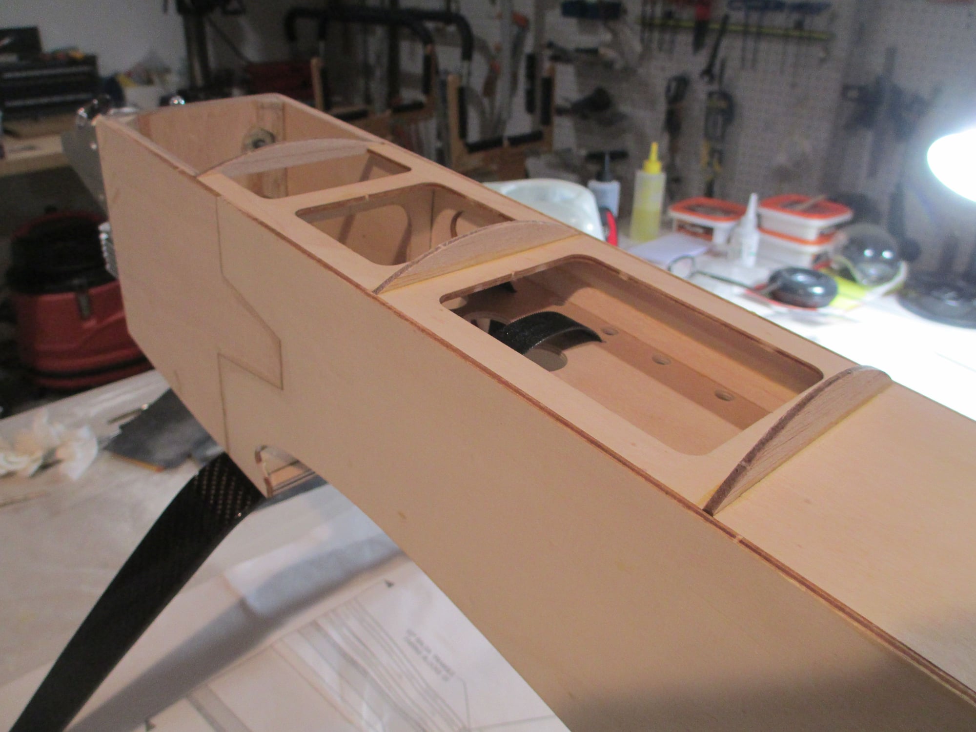
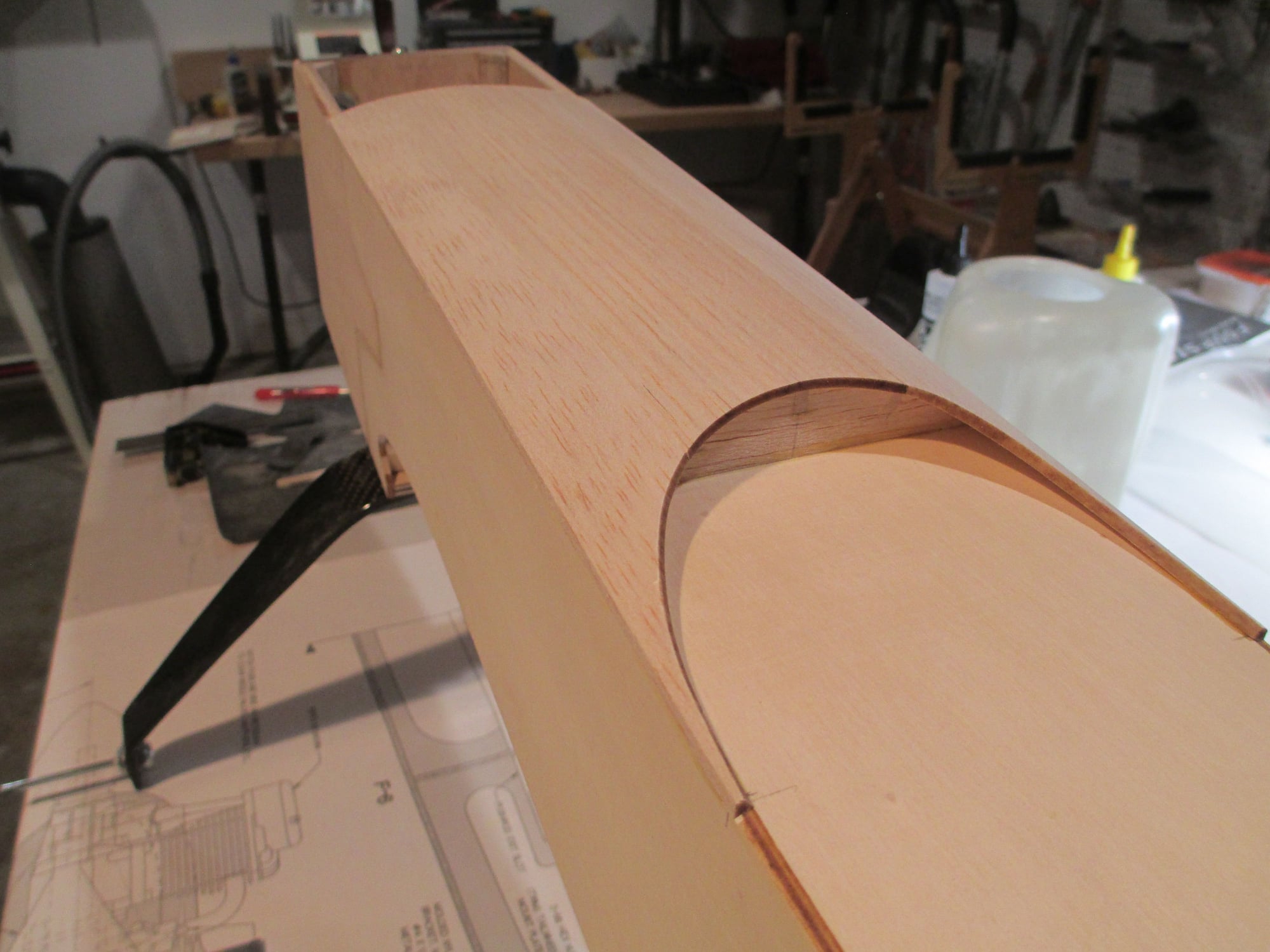
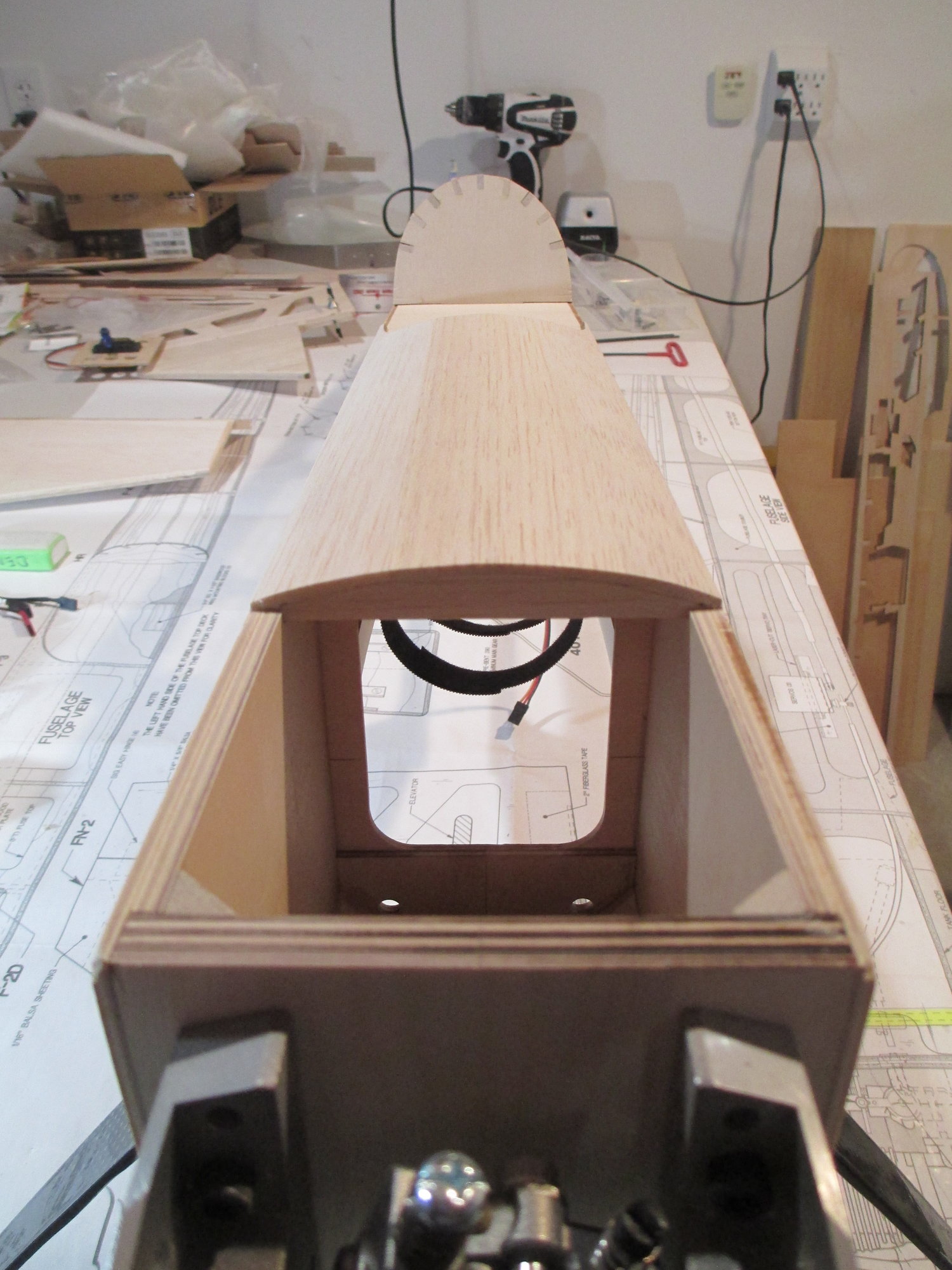
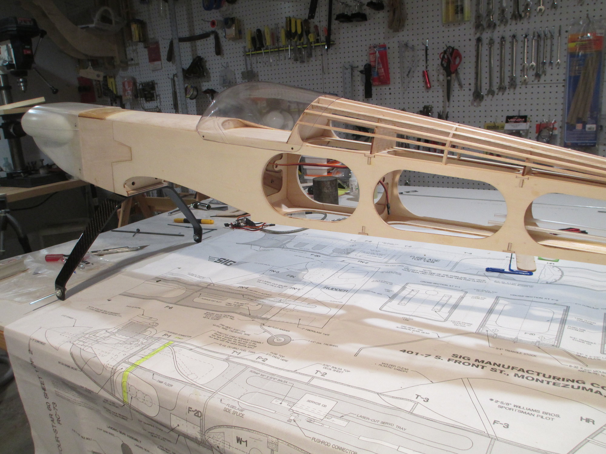
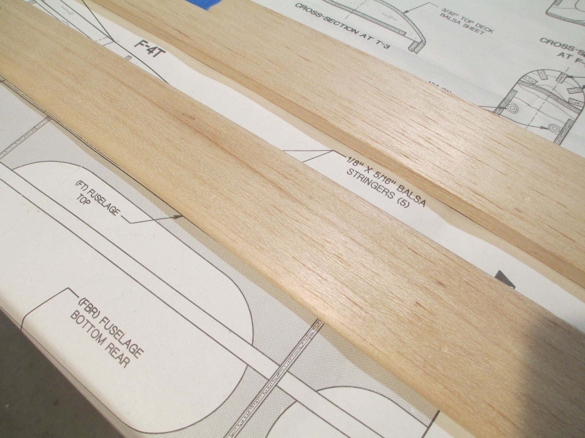
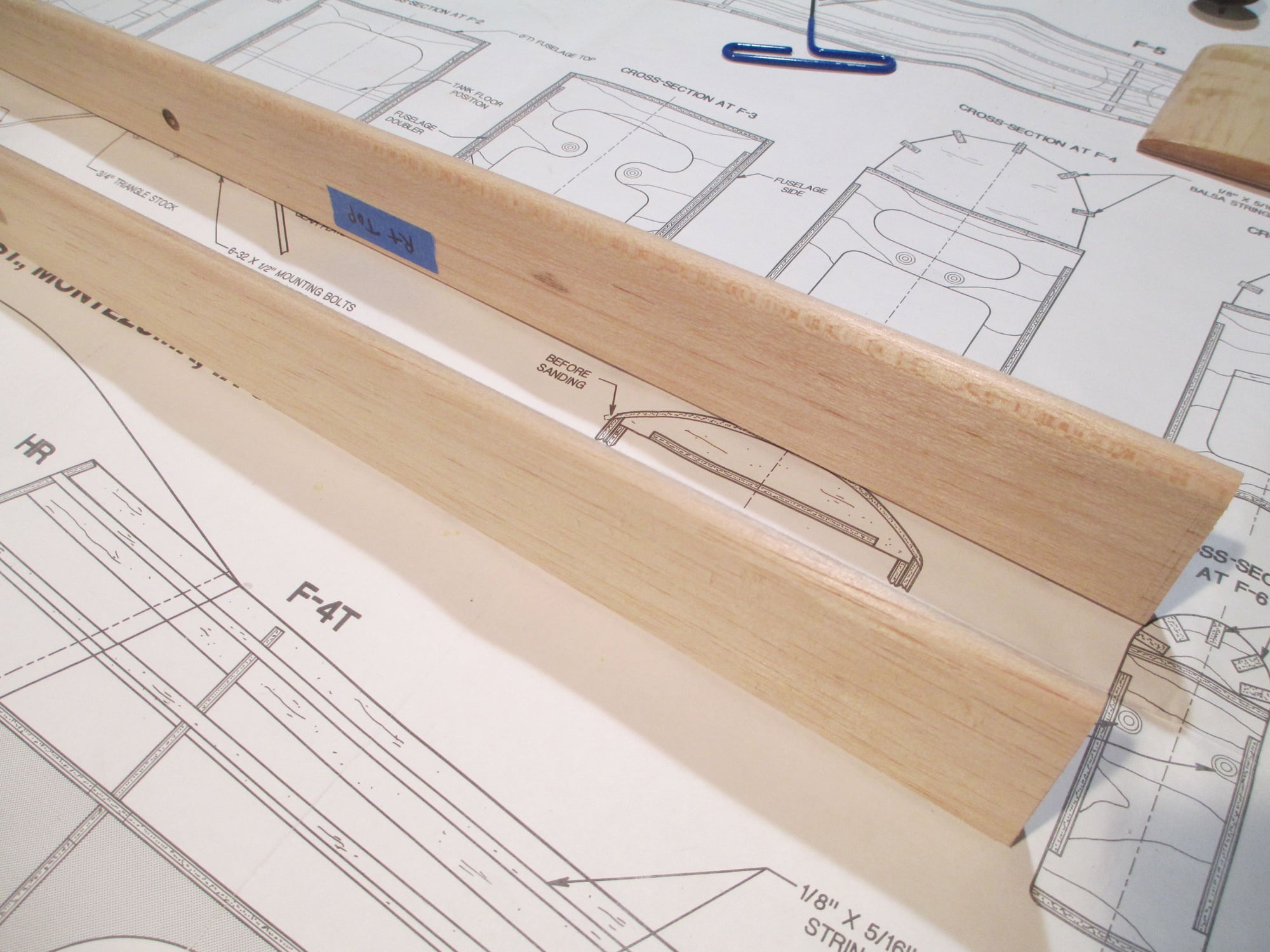
Really the last bit of construction/building for this plane. These are the Top Formers (T-1, T-2 and T-3) that support the top deck sheeting. The sheeting is to be glued right over these formers without any other support.
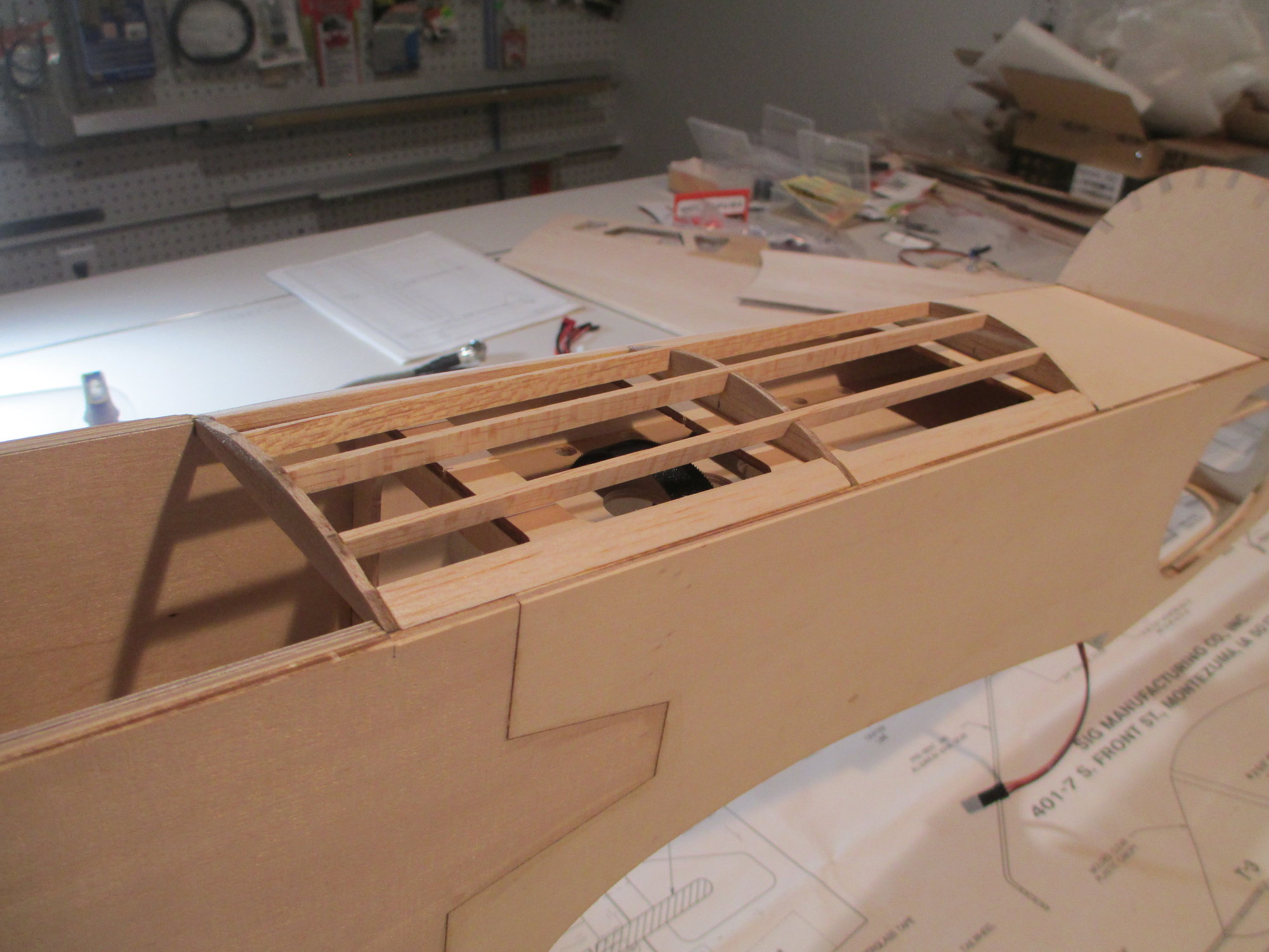
I wanted to add more support for the top deck sheeting, so these stringers were added.
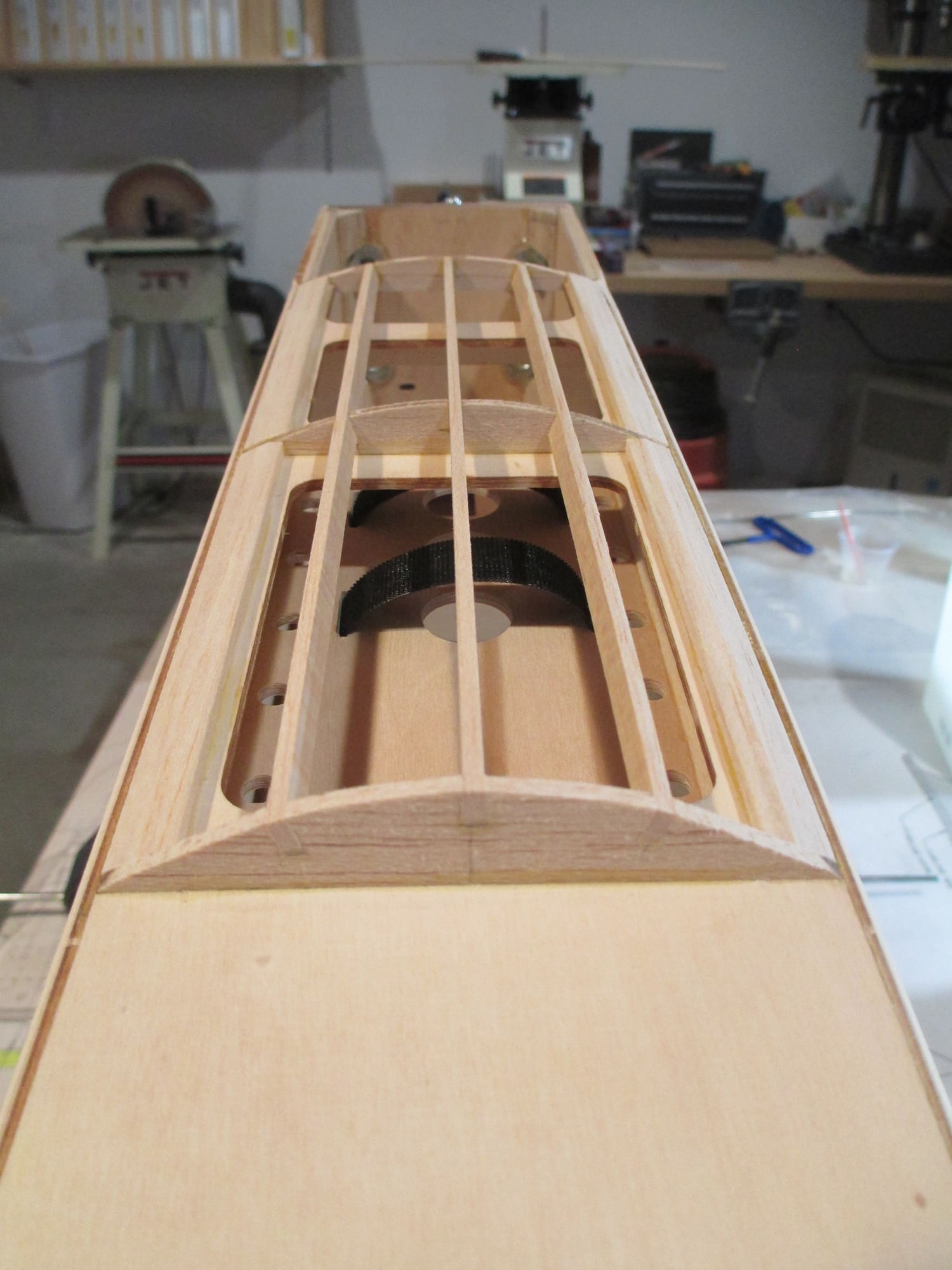
Ready to glue the sheeting in place now.
 04-26-2019, 05:05 AM
#132
Thread Starter
 04-26-2019, 09:30 AM
#133
Thread Starter
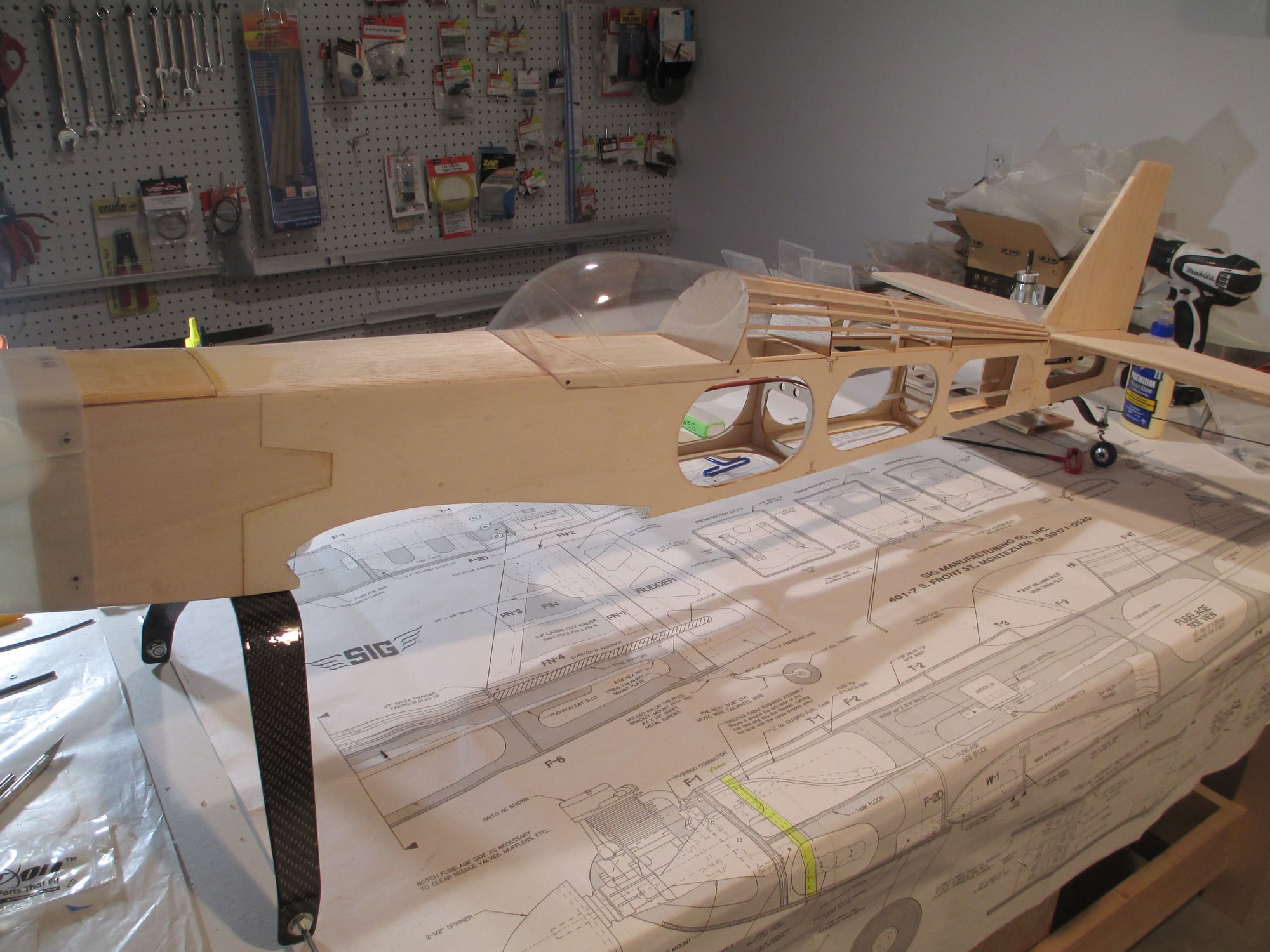
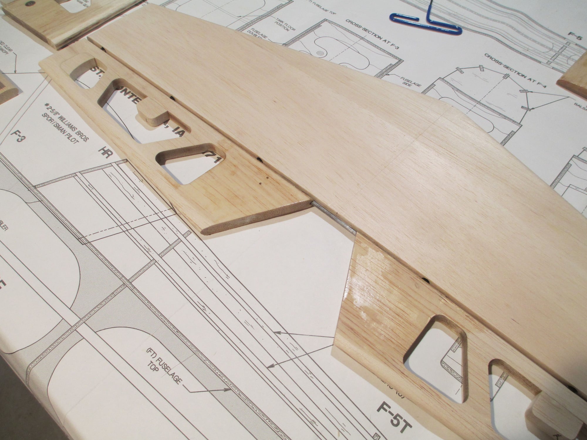
Top deck sheeting is done minus the sanding and shaping of course.
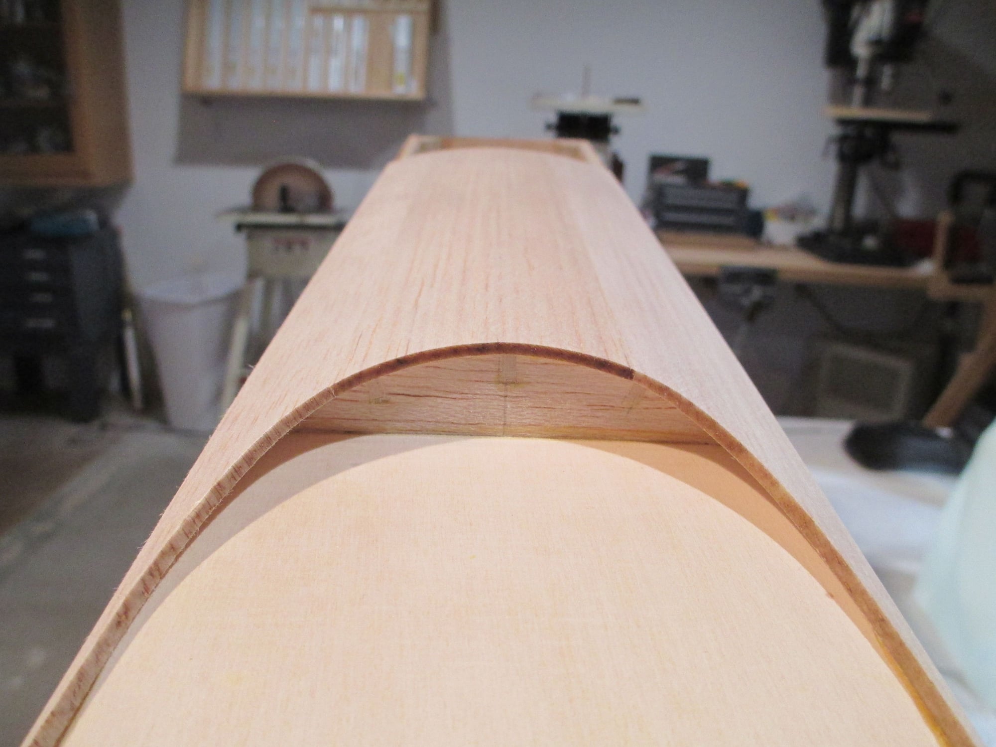
Adding the stringers really stiffened things up.
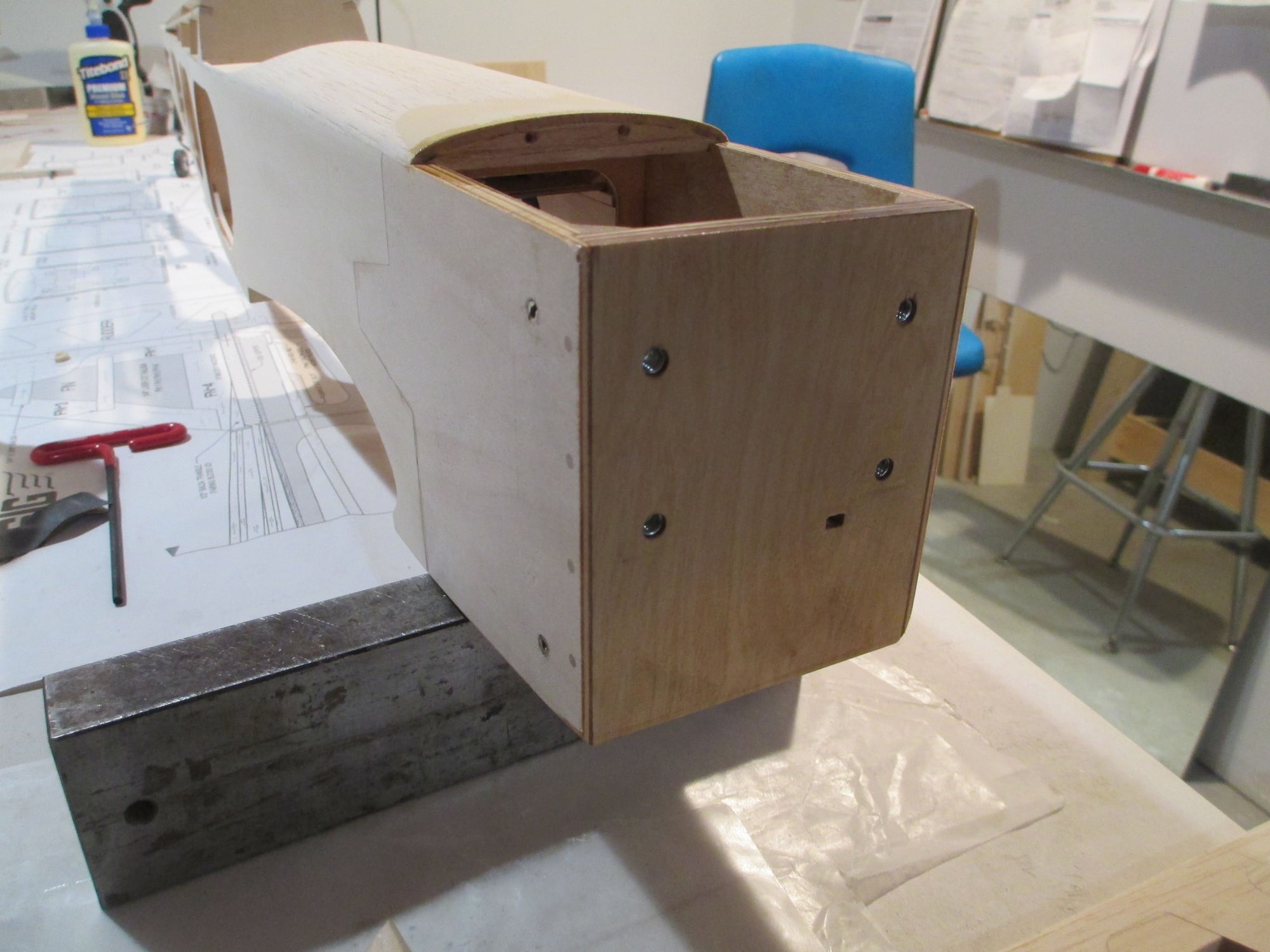
I didn't run the sheeting all the way to the firewall because I'm building a removable cover that will transition to the cowl and give me access to the throttle servo. Should be fun to build!
 04-27-2019, 11:49 AM
#134
Thread Starter
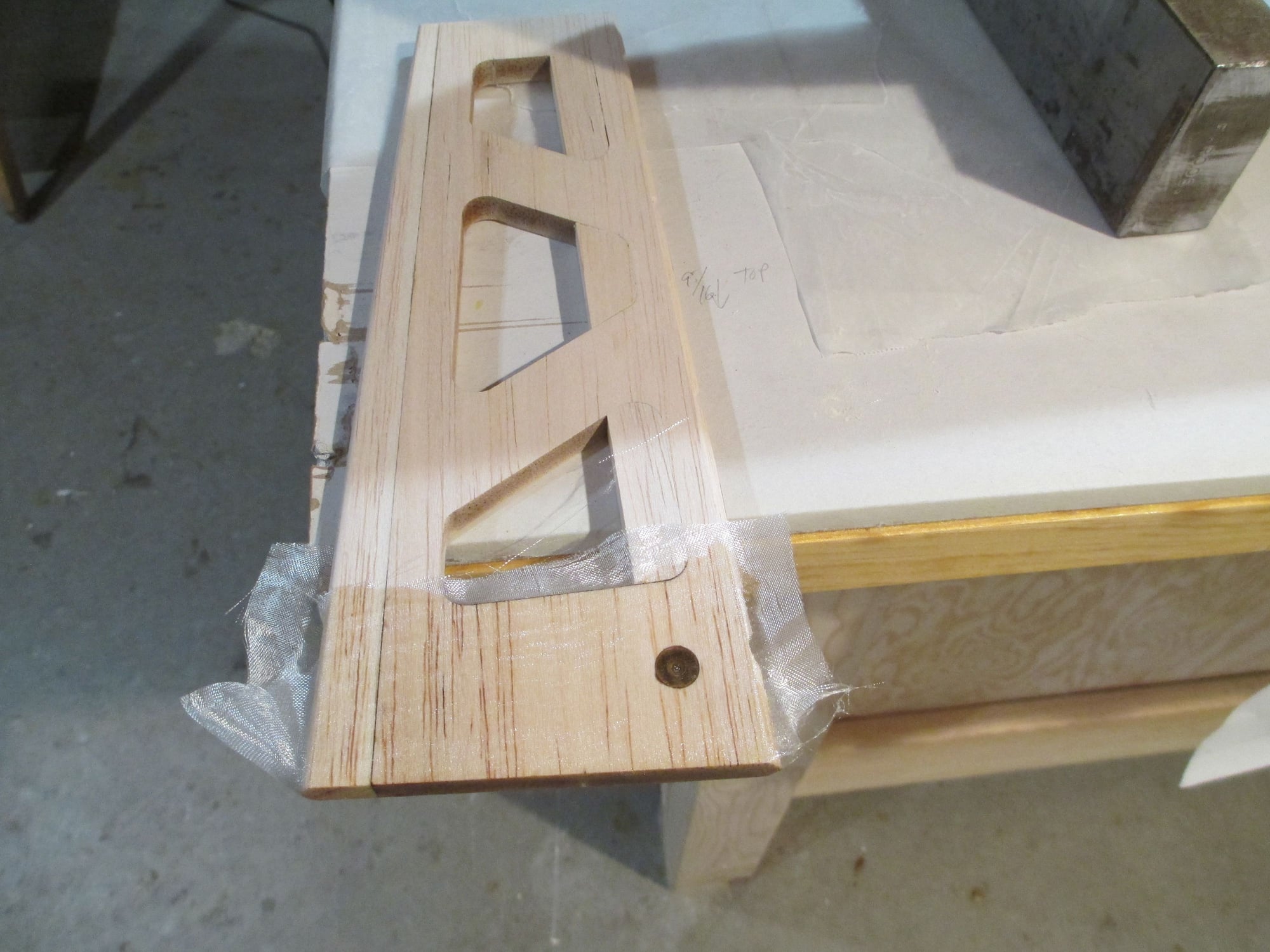
Here's what I came up with to have access to the throttle servo (and ignition box). I was going to hold it in place using magnets, but the simplicity of using dowels won out. I made it from very light 3/8" balsa, to which I epoxied 1/16" birch ply on the bottom for strength.
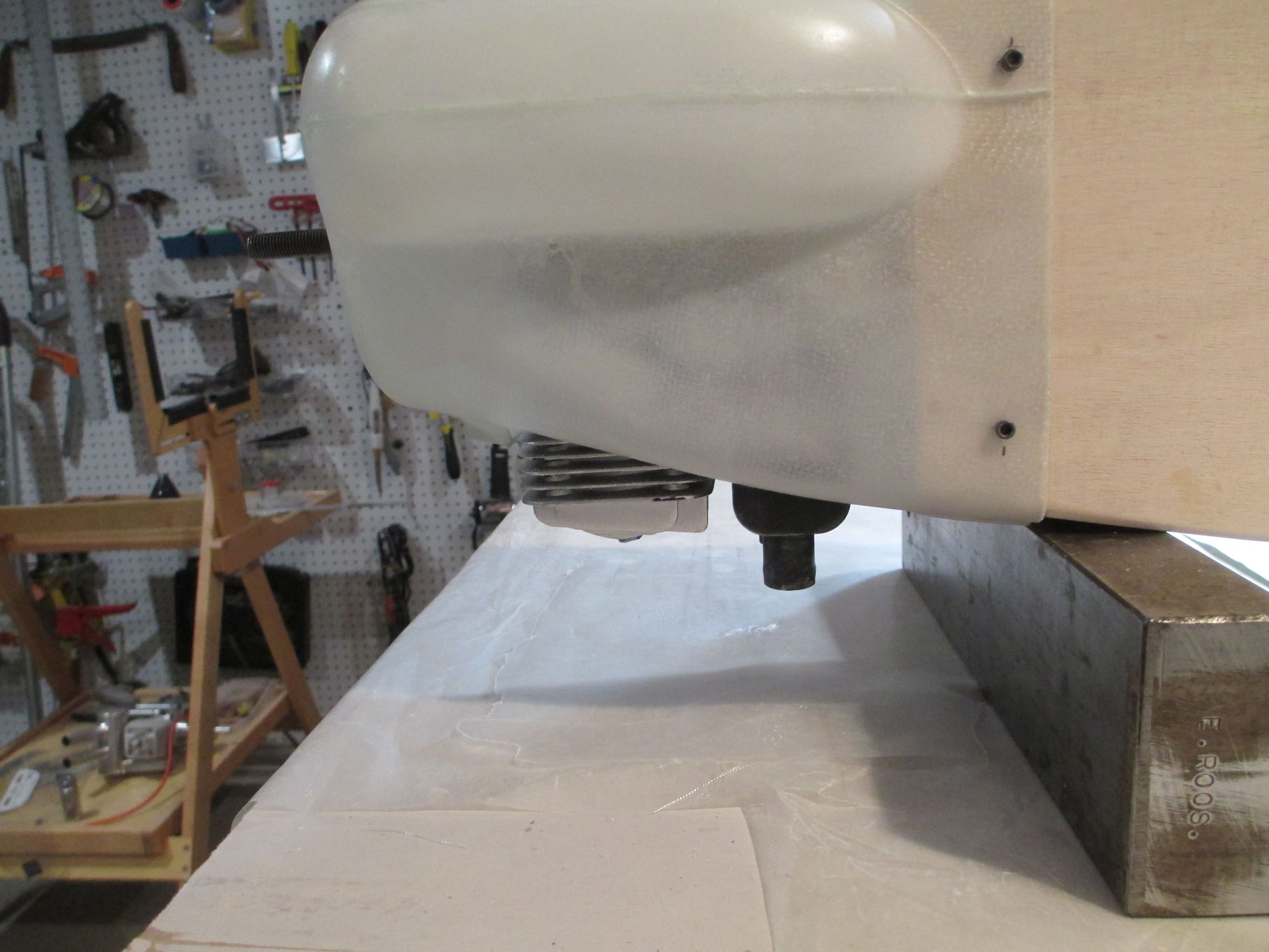
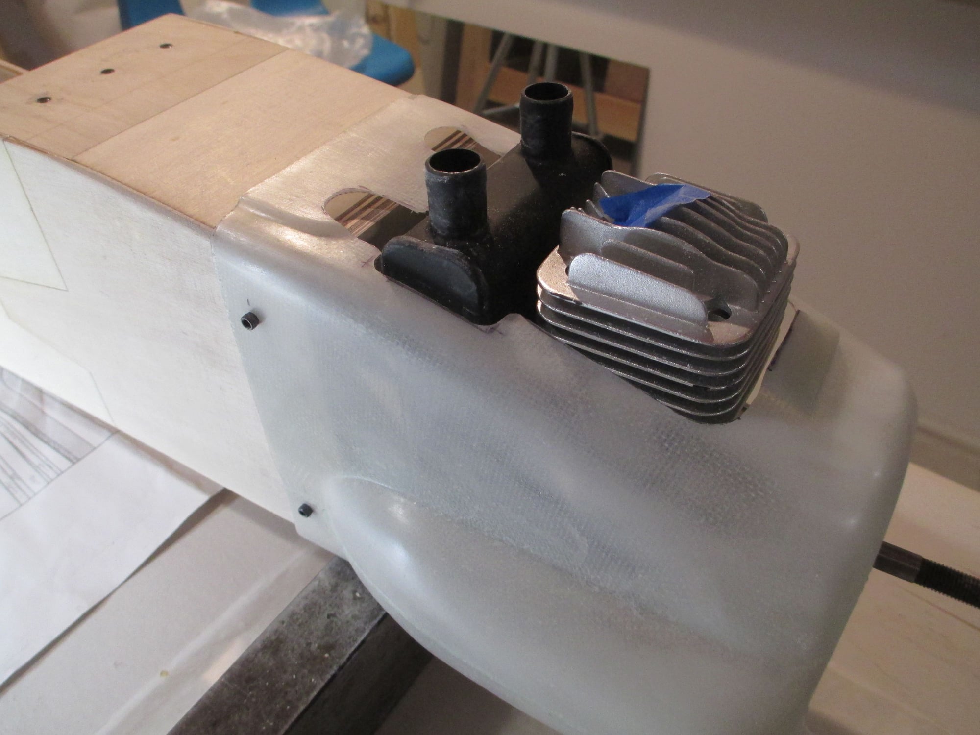
I also took the time to fit the cowl. The engine prop shaft exits dead center in the front opening as planned. It was a bugger though to get this cowl to fit properly. The problem I ran into was the top of the cowl is flat, while the top of the deck is curved. I had to transition is as best I could with out restructuring the whole deck. As much as I try not to use any filler in my builds, I did have to use a very small amount to get it to transition right.
All in all the cowl fits well. Keeping in mind that this plane was never designed to have one.
Four 4-40 cap head bolts hold the cowl in place, more on that in a minute...
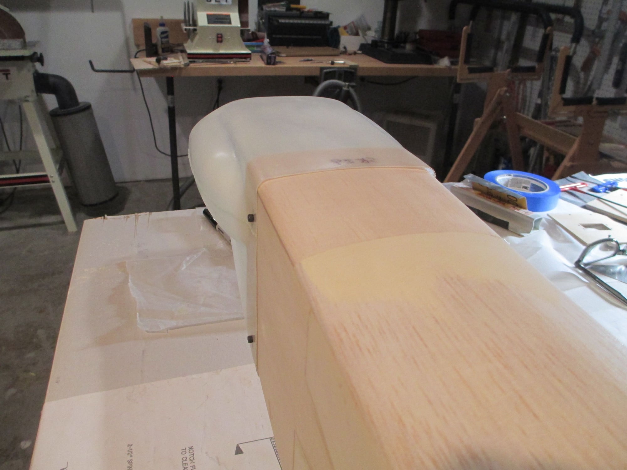
I tried to photograph the cowl on all different angles to show the fitment in case anyone is interested in putting one on theirs.
Top view.
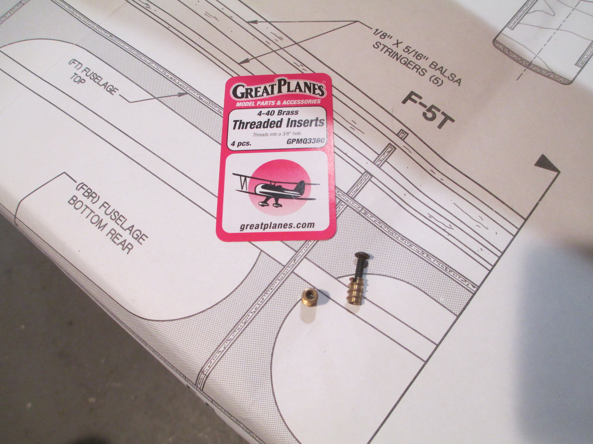
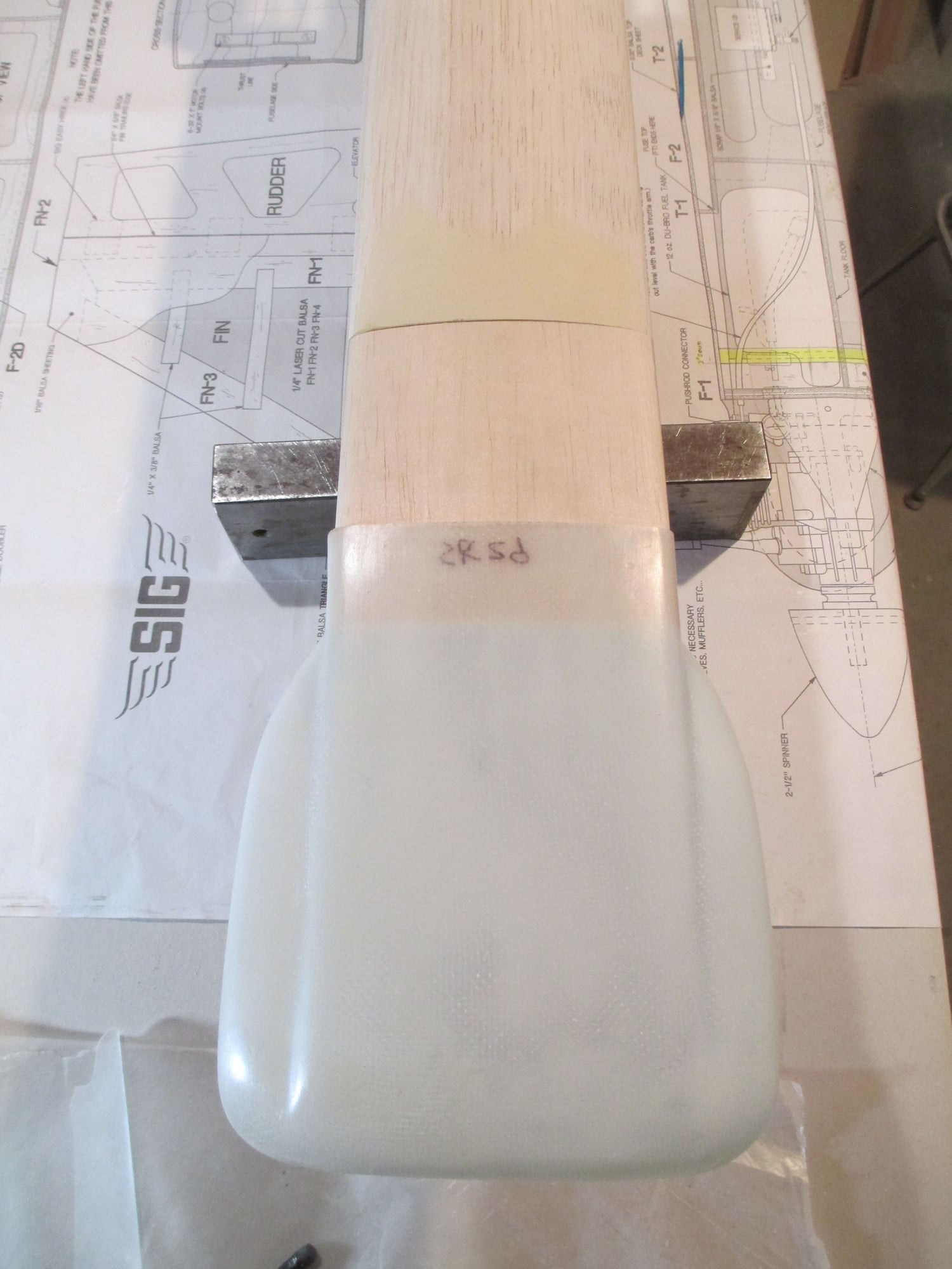
OK, here's what I used to secure the cowl to the fuselage. These are nothing new in the woodworking world, they have been used in many woodworking projects. Simply drill a hole and screw them in (I also used a bit of epoxy on the threads).
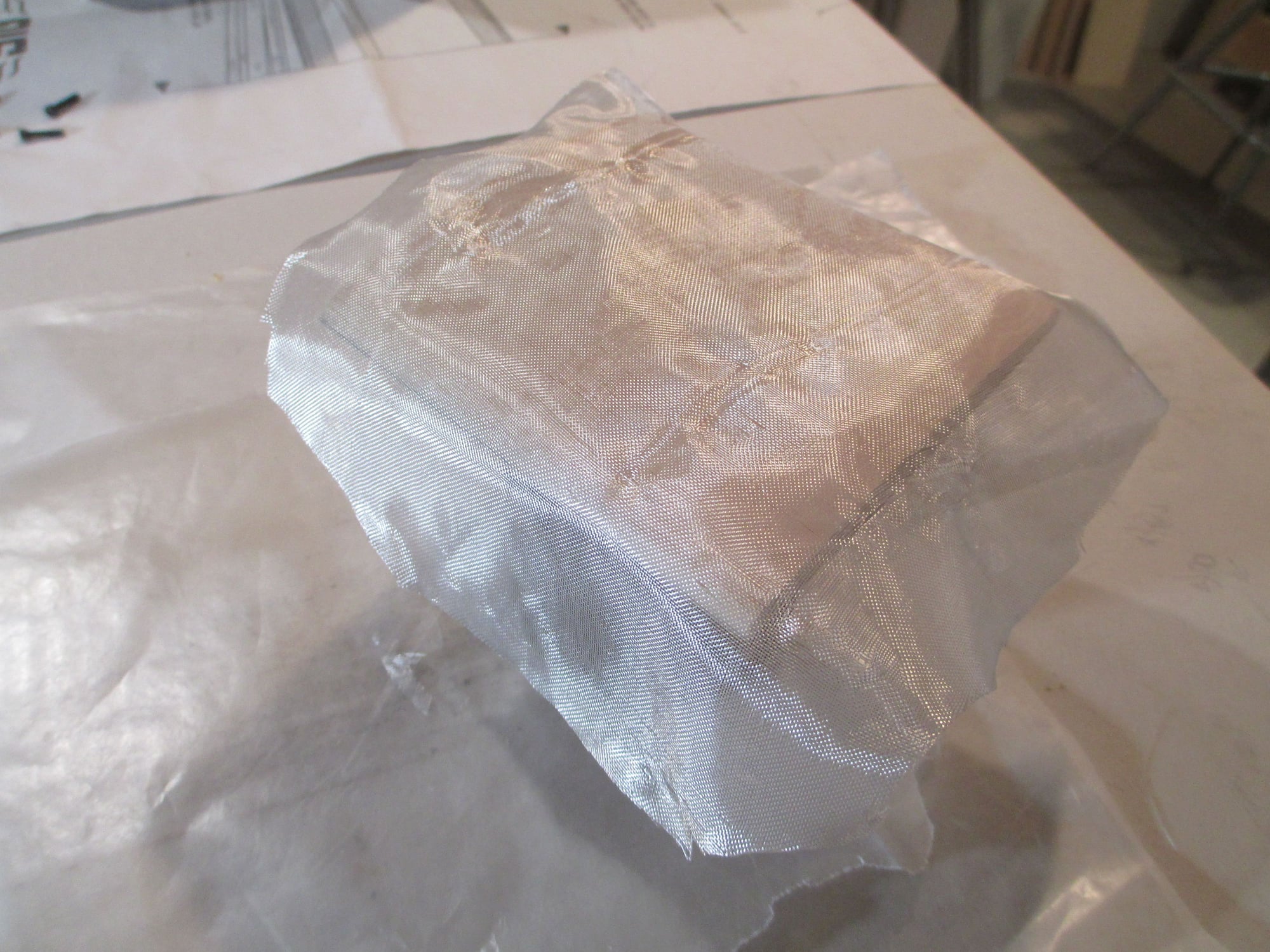
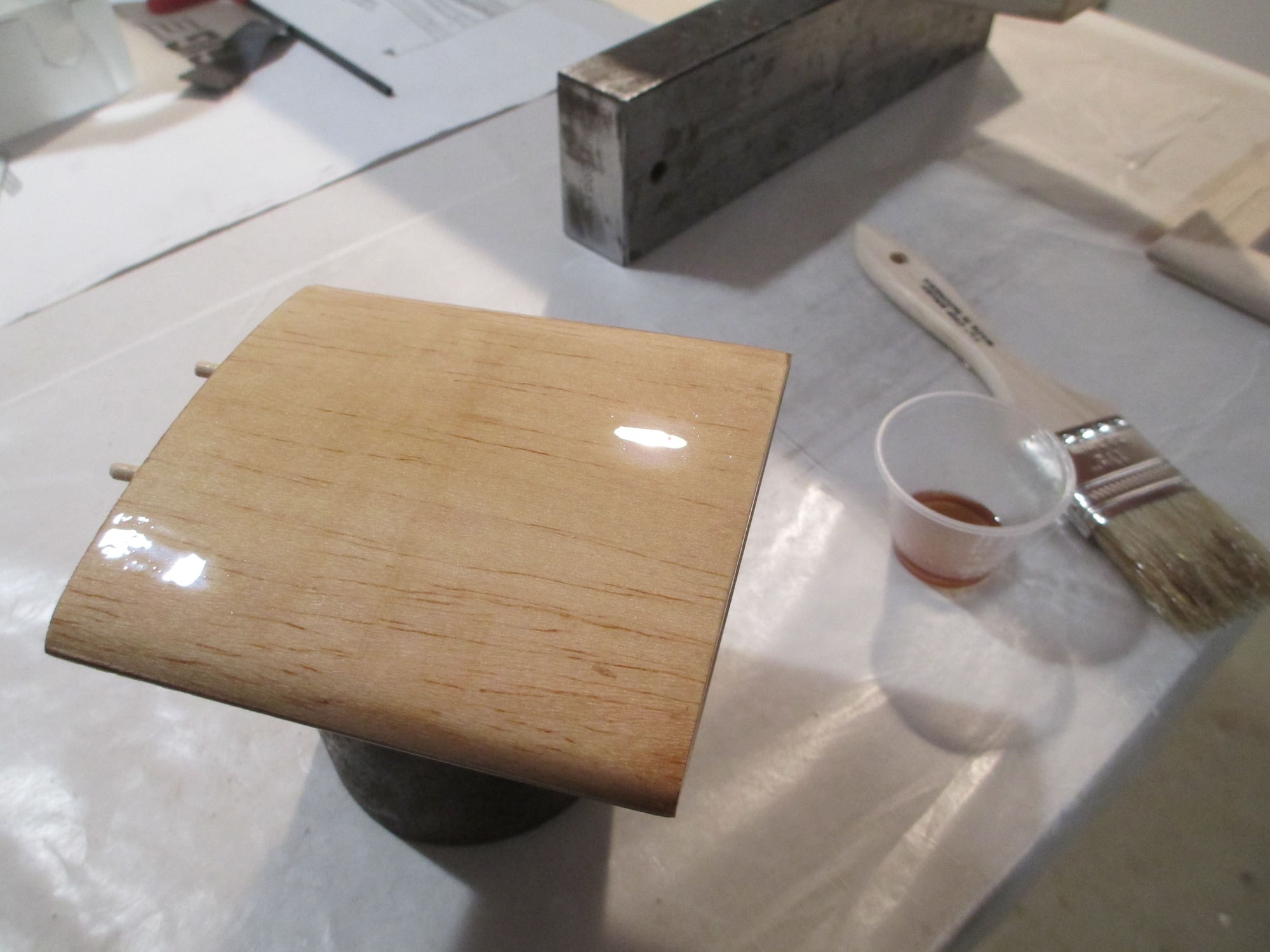
I decided to glass the newly made hatch. I'm using 1/2 ounce cloth.
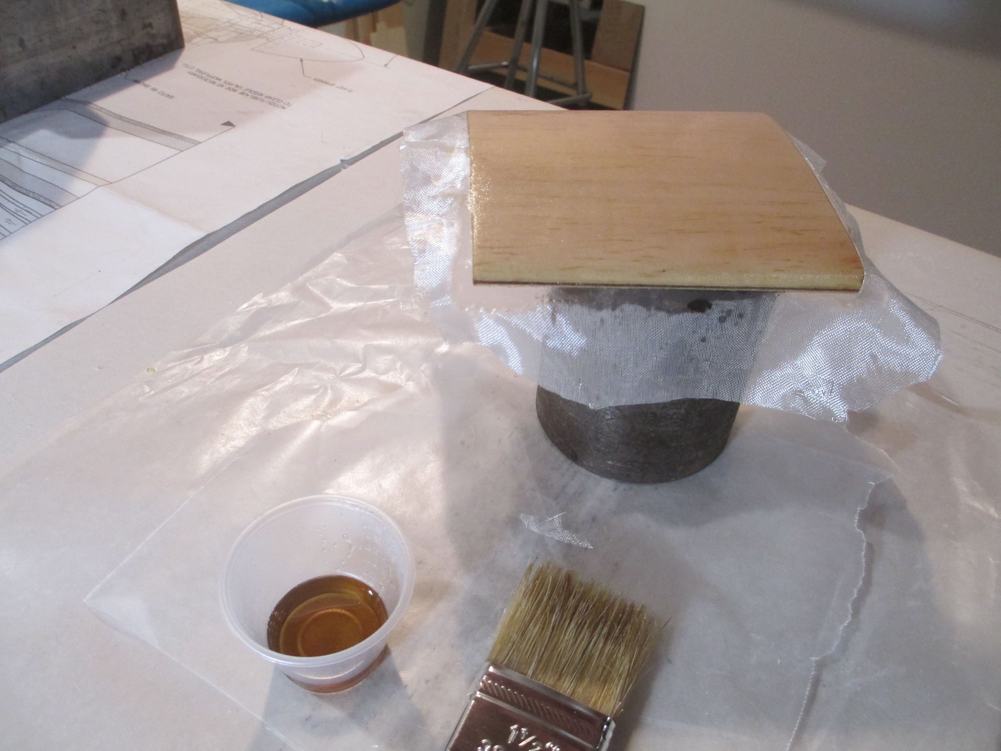
As I has explained before I cut my finishing resin with denatured alcohol and brushed it on.
When dry I will trim the cloth and give it it second (and final) coat.
Last edited by VincentJ; 04-27-2019 at 11:54 AM.
04-27-2019, 03:17 PM
#135
Thread Starter
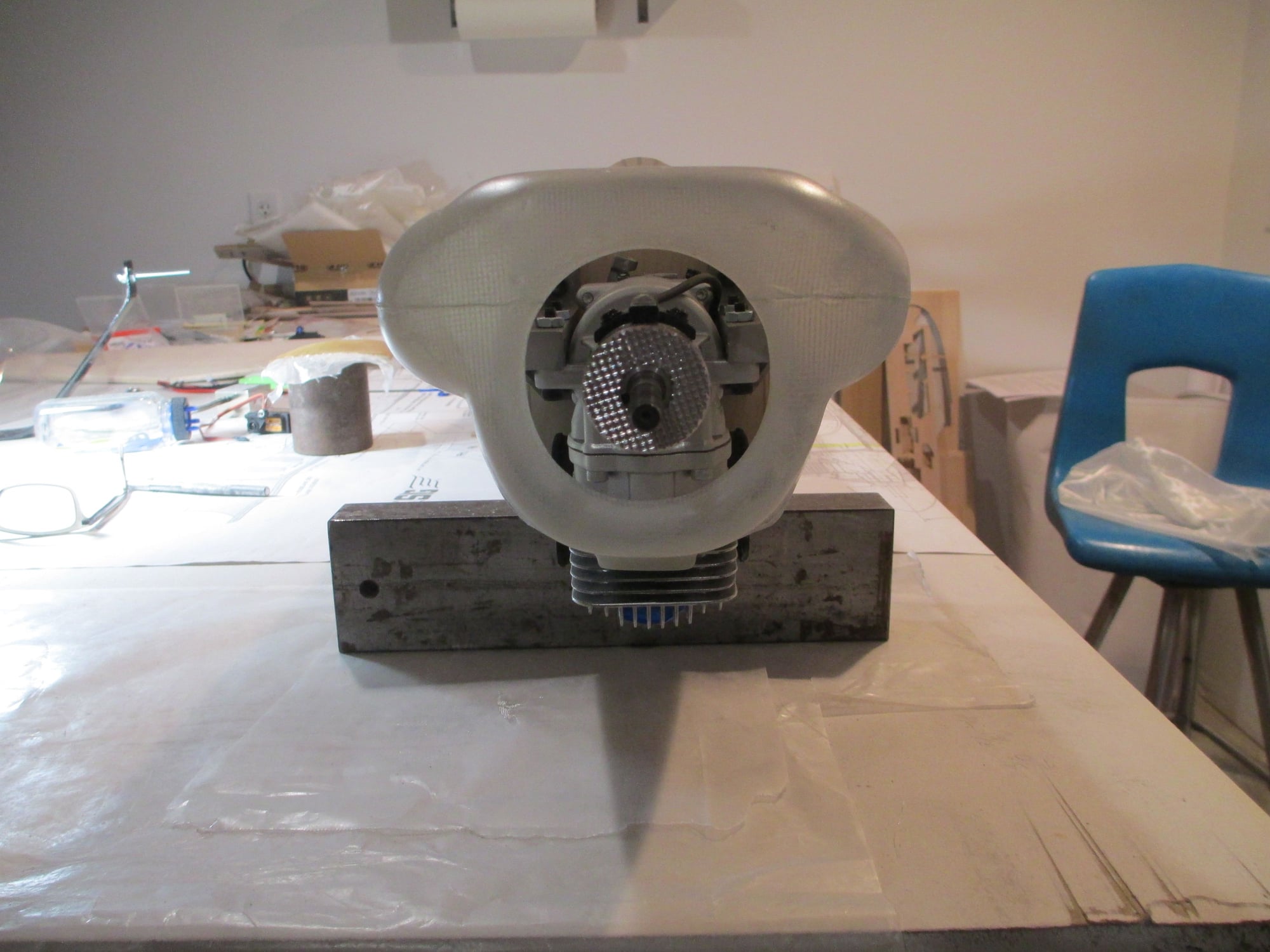
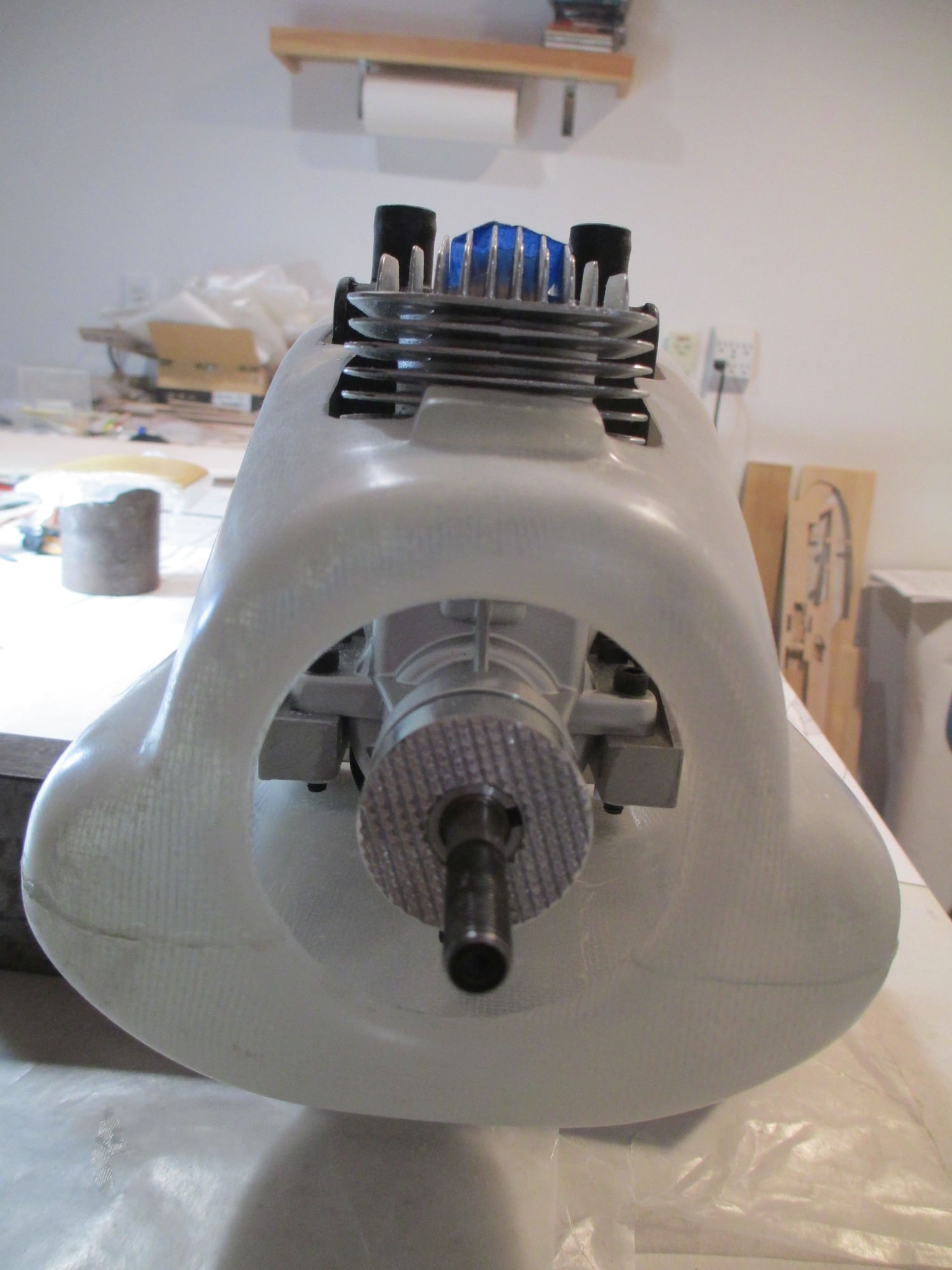
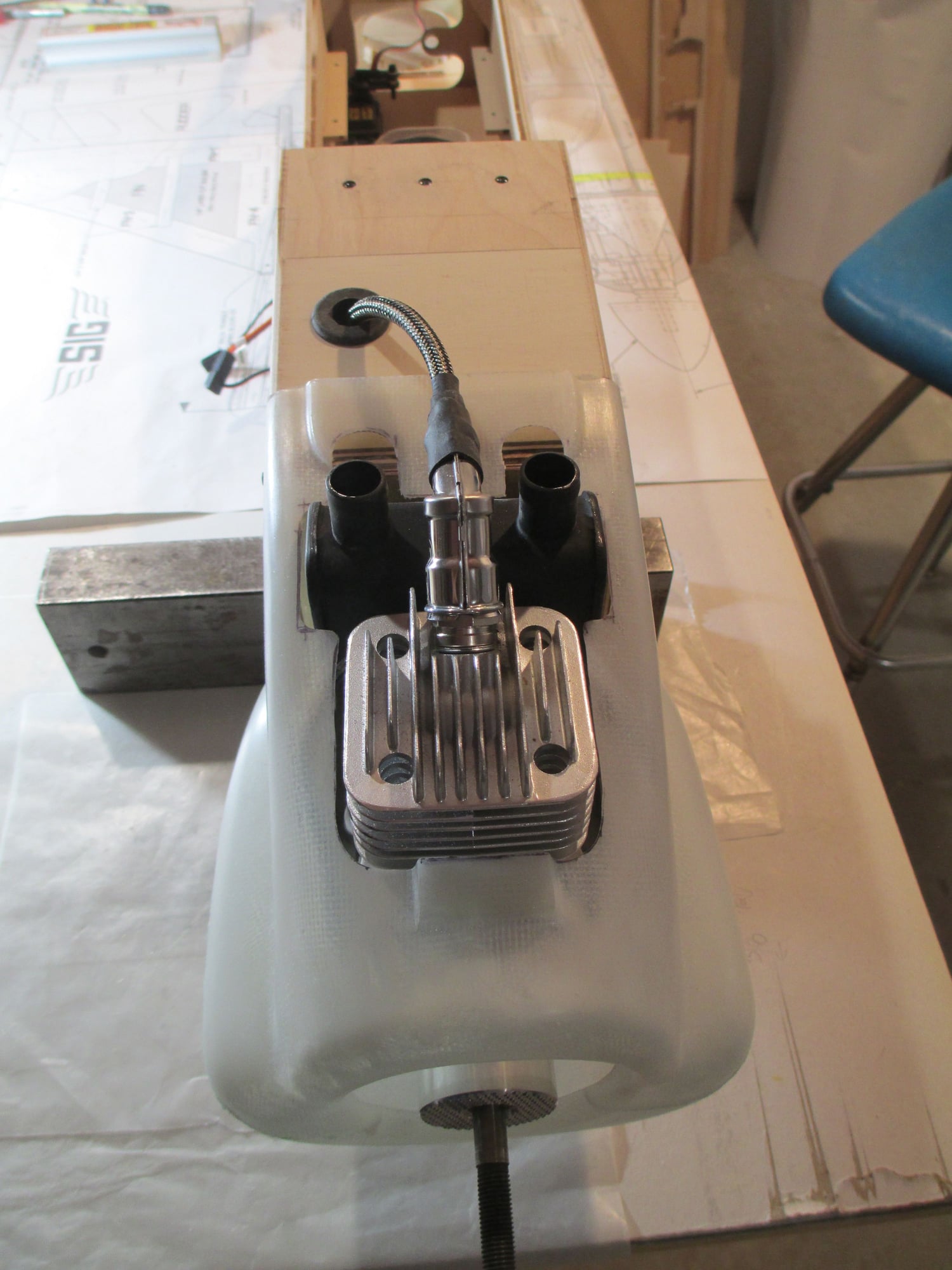
Prop shaft is right on center.
I really like how well the DLE-20RA engine fits.
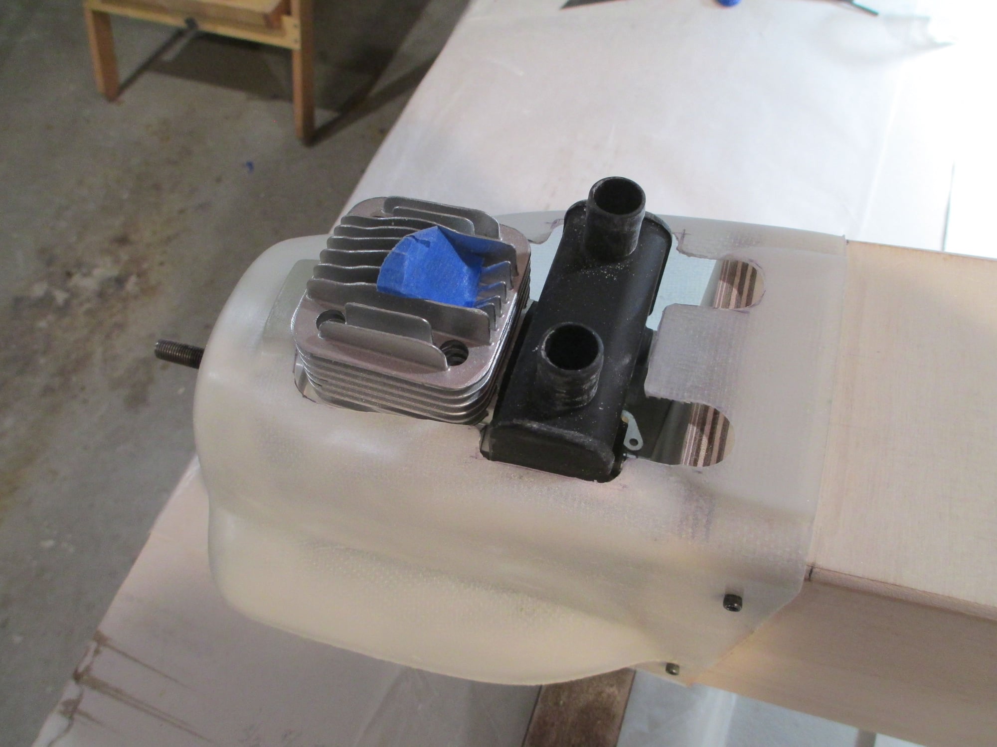
I was careful removing only what was necessary on the cowl.
I still need to make an opening for the spark plug wire to exit...
 04-28-2019, 01:16 AM
#136
Thread Starter
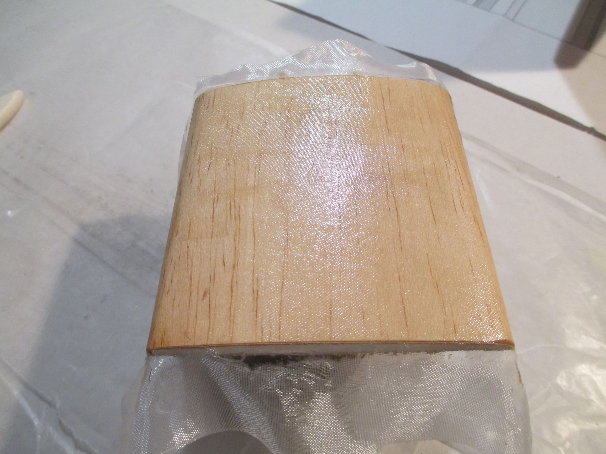
2nd coat of finishing resin applied.
Wrapped the bottom of the rudder in fiberglass cloth.
No cloth on the firewall, however I did apply finishing resin.
04-28-2019, 12:56 PM
#137
Thread Starter
Checked off another item off my punch list. I drilled the hole in the bottom of the fuselage to allow the spark plug wire to pass through.
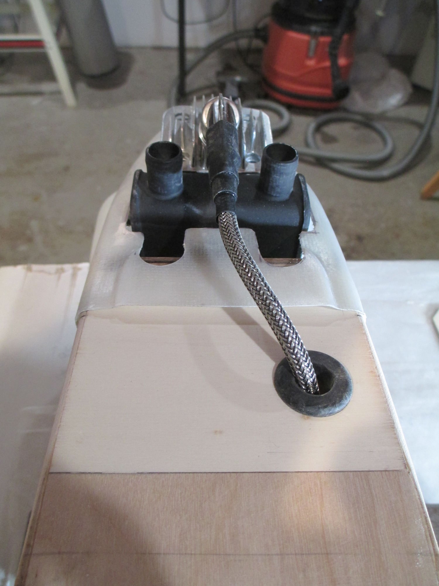
The hole is very large (about 3/4") to allow the spark plug connector to pass through. I don't know why manufacturers of these ignition boxes don't make a removable (plug-in) wire, similar to what the automotive industry has used for years. A much smaller opening would be needed and it would make for easier maintenance.
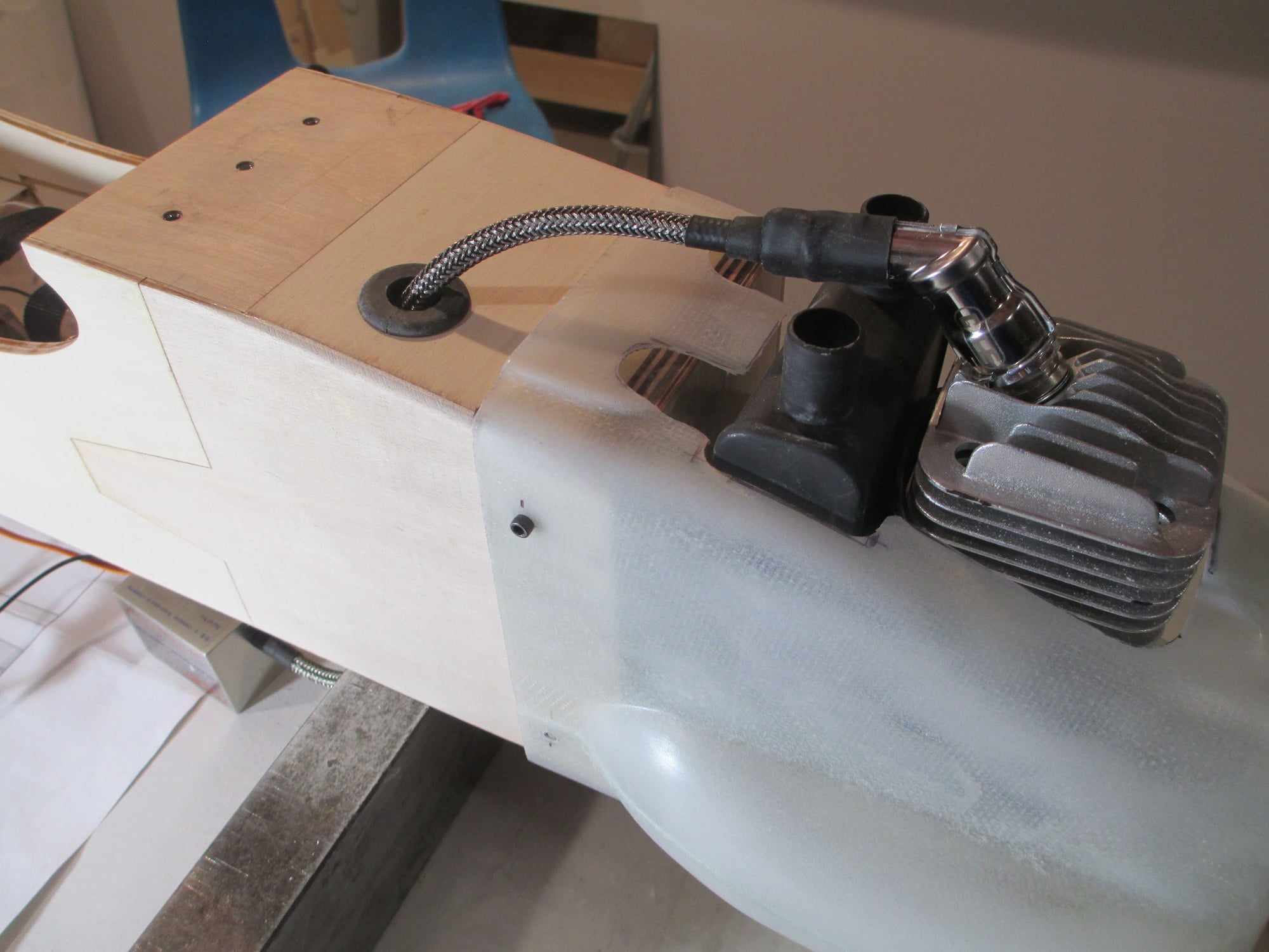
You may be wondering why I offset the hole which is by design and not by accident. I knew that in the front of the fuselage where I put the throttle servo would mean that I would have to offset the spark plug wire opening.
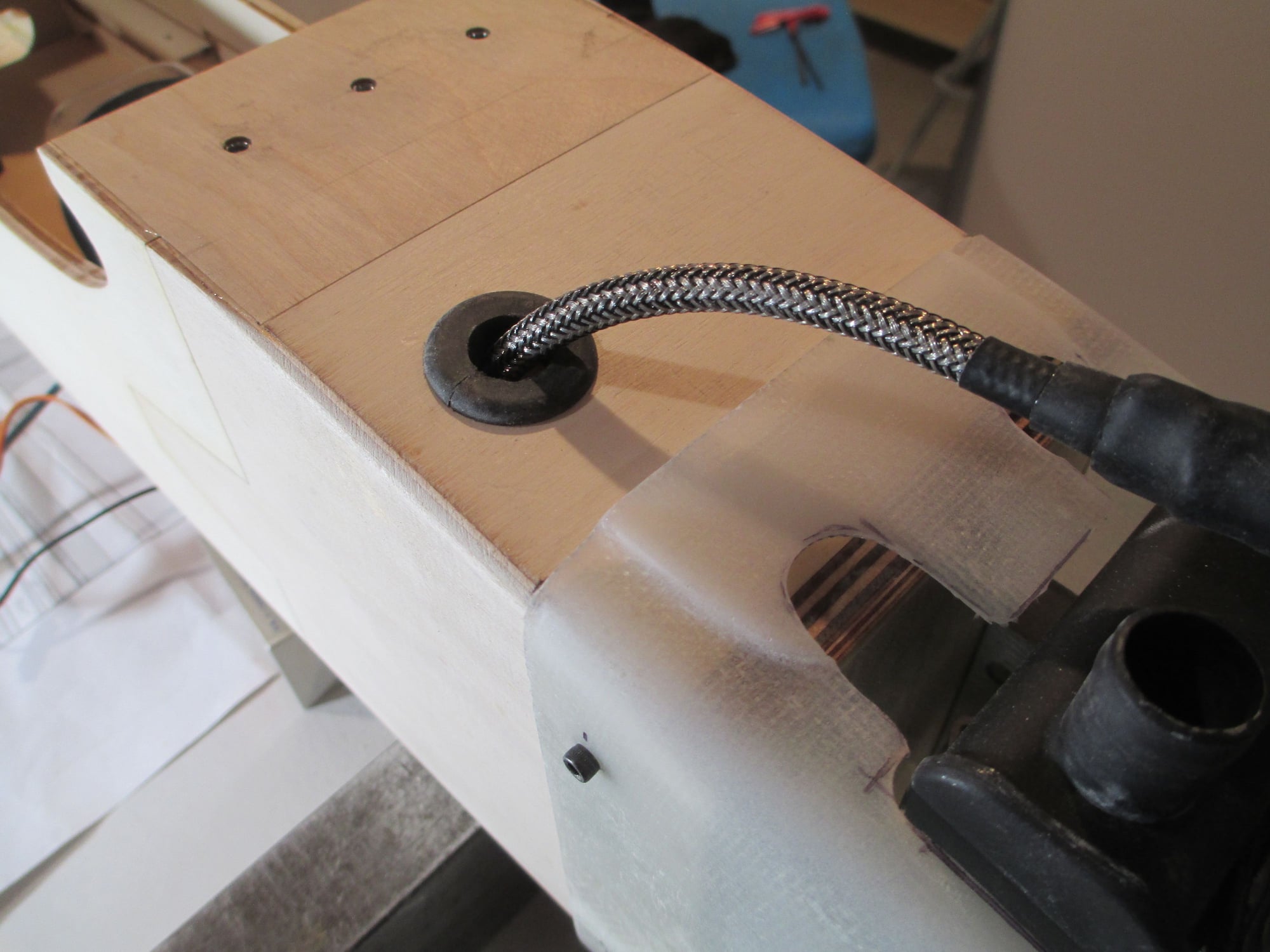
Gasser's make a lot of vibration, and vibration could mean trouble with wires that are passing through openings causing wires to chafe. Whenever possible I like to use a rubber grommet to stop the chafing. These rubber grommets can be purchased at your local hardware store and they come in a variety of sizes.
Last edited by VincentJ; 04-29-2019 at 05:31 AM.
05-01-2019, 03:14 PM
#138
Thread Starter
I never really liked the bulby shape of the stock Four Star's canopy, so I trimmed it down to something I think is more appealing... The four corners of the canopy are screwed down. The canopy will get glued once the plane is covered.
Last edited by VincentJ; 05-02-2019 at 12:44 AM.
05-02-2019, 03:32 AM
#139

Thanks for that tip on the threaded inserts. I�ve used them many times on woodworking projects. I used them when I made my wing building jig. I can easily change from a 36� to a 48� wing build. I saved the part number. Will have to order some.
Nice build, learning a few things, following along.
05-02-2019, 04:58 AM
#140
Thread Starter
Thanks for that tip on the threaded inserts. I�ve used them many times on woodworking projects. I used them when I made my wing building jig. I can easily change from a 36� to a 48� wing build. I saved the part number. Will have to order some.
Nice build, learning a few things, following along.
05-04-2019, 02:43 AM
#141
Thread Starter
Sanding/shaping has begun. I always try to give special attention sanding all the parts to achieving the right profile. It takes a while, but the effort pays off with good looks and good performance in the air.
Be sure while sanding to wear a sanding mask or some sort of respirator to keep the balsa dust out of your lungs. I wear a sanding mask and my Jet air filter beneath my build table is also on.
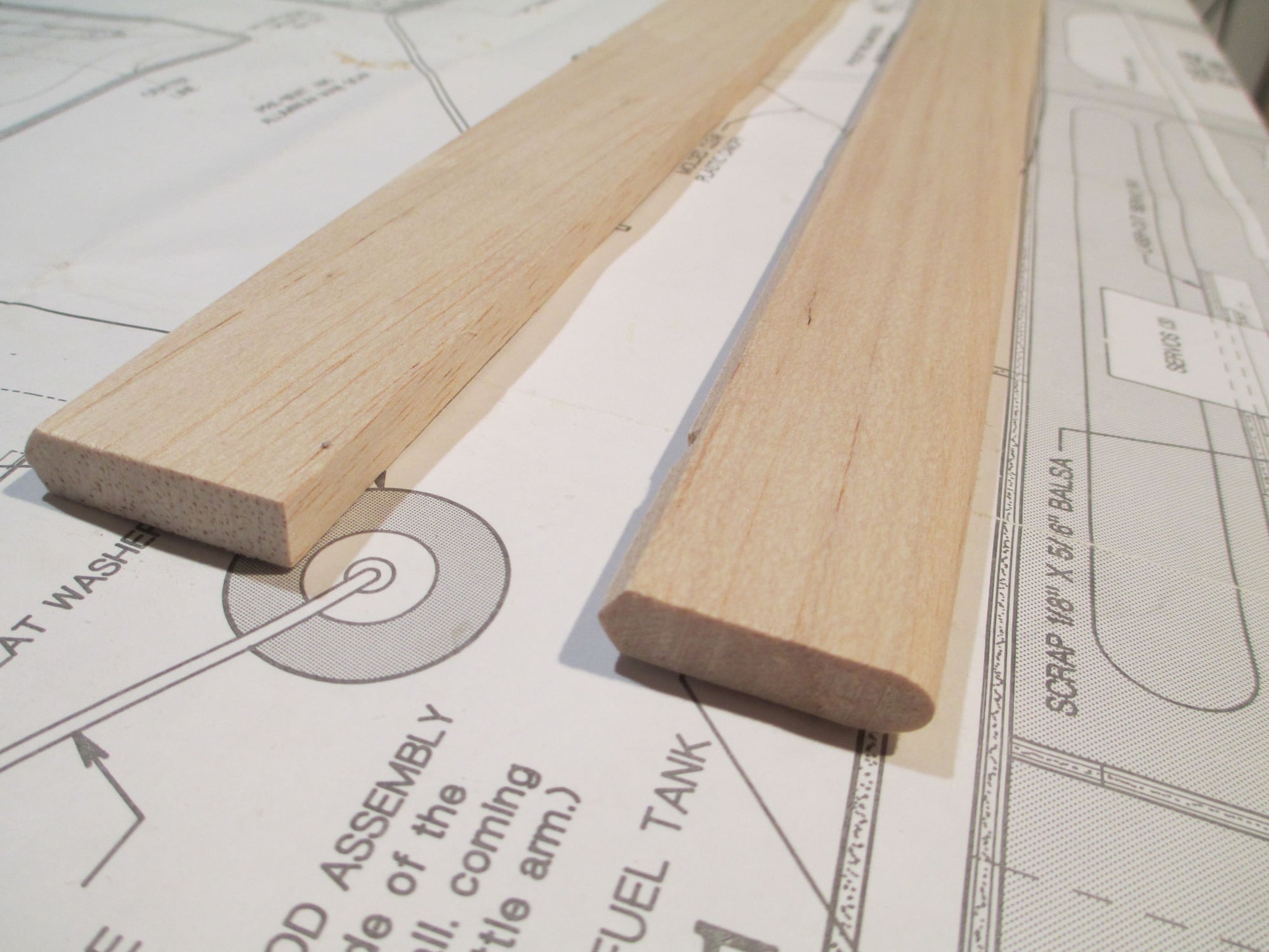
Before of left, after on right.
Top is before and the bottom is after.
Both are now shaped. This gets rid of the "boxy" look that they had. Its important that your profile is consistent from left to right.
Elevators and stabilizer have also been shaped...
as well as the rudder and fin.
Be sure while sanding to wear a sanding mask or some sort of respirator to keep the balsa dust out of your lungs. I wear a sanding mask and my Jet air filter beneath my build table is also on.
Before of left, after on right.
Top is before and the bottom is after.
Both are now shaped. This gets rid of the "boxy" look that they had. Its important that your profile is consistent from left to right.
Elevators and stabilizer have also been shaped...
as well as the rudder and fin.
Last edited by VincentJ; 05-04-2019 at 02:48 AM.
 05-05-2019, 06:23 AM
#143
Thread Starter
Last edited by VincentJ; 05-05-2019 at 06:29 AM.
05-05-2019, 06:36 AM
#144
Thread Starter
The "to do" list is getting shorter! Other than the obvious sanding, every thing has been constructed/fitted with the exception of three items before the covering can begin. First, the rudder's nylon exit tube needs to be installed, second, the wheel pants need to be installed and finally, all fiberglass parts as well as the firewall need to be spray painted...
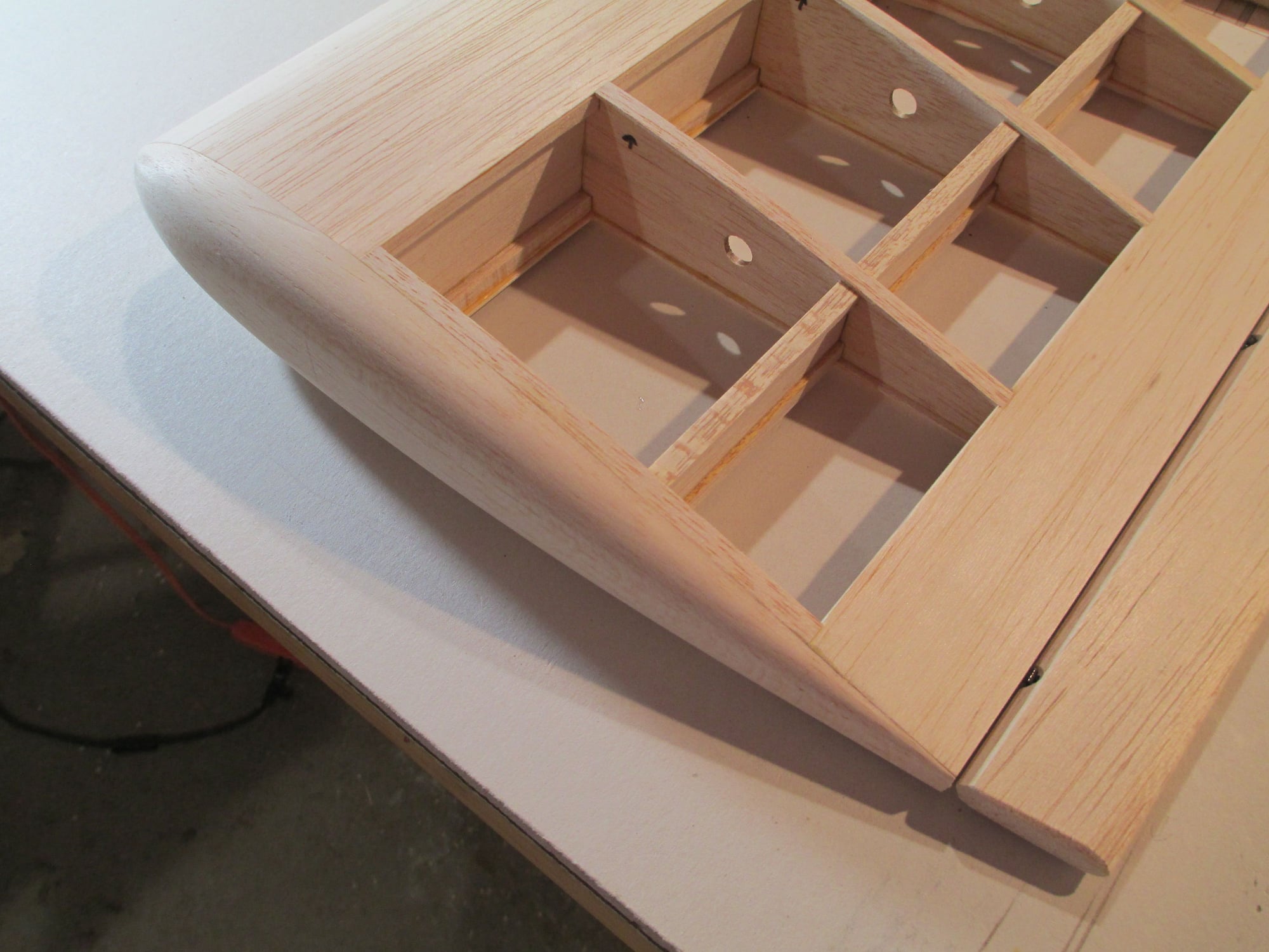
Both wing tips have been shaped and glued to the last wing rib.
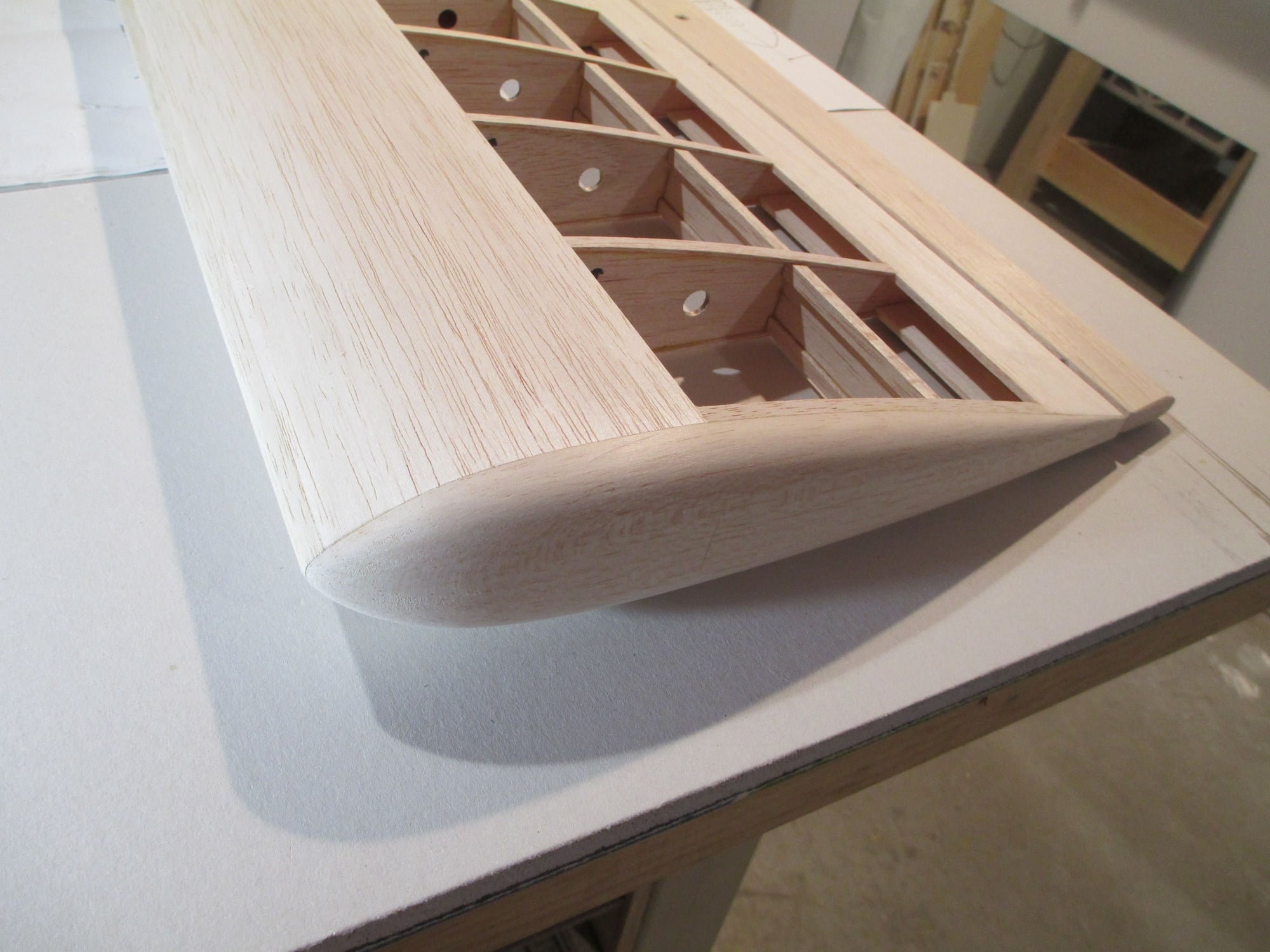
It's easy to shape one wing tip, but a bit more difficult to make the next one the same size and shape as the first.
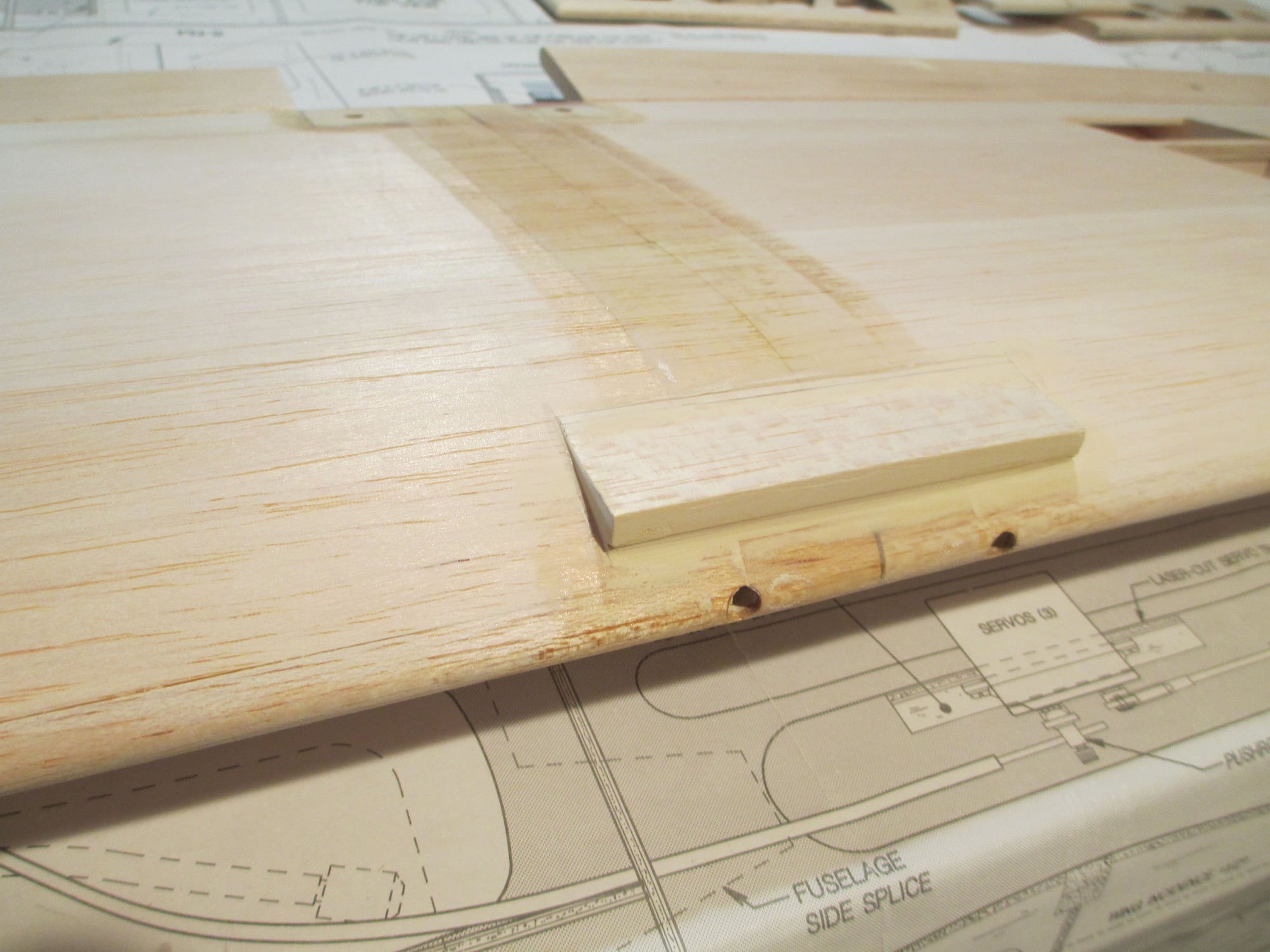
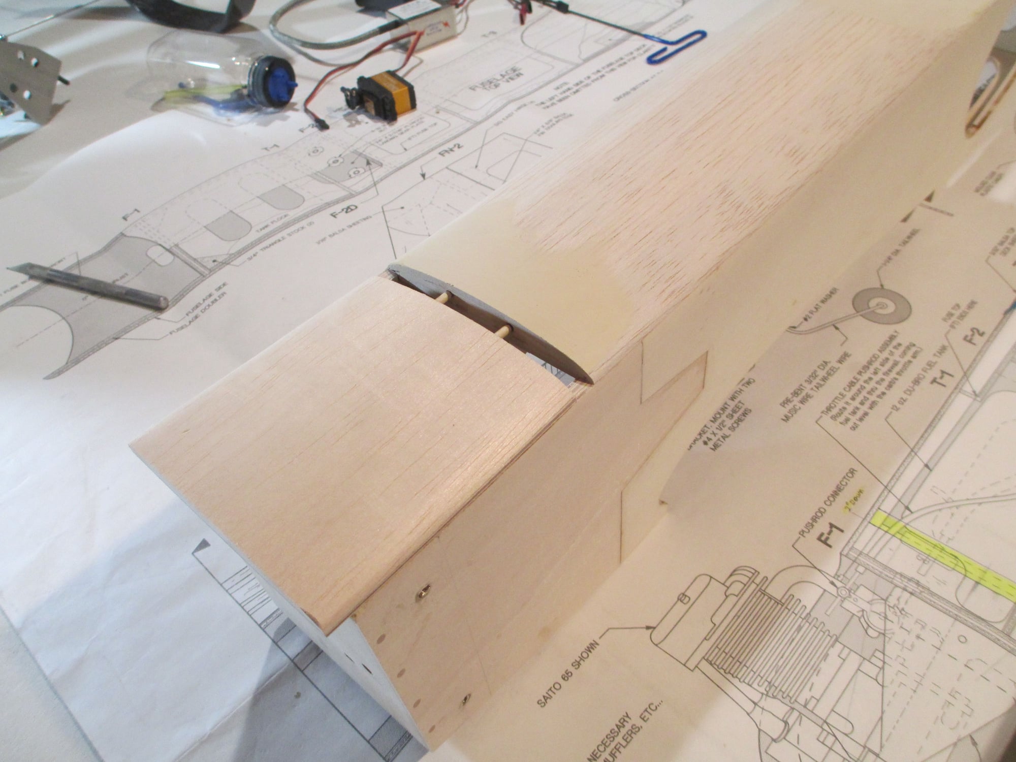
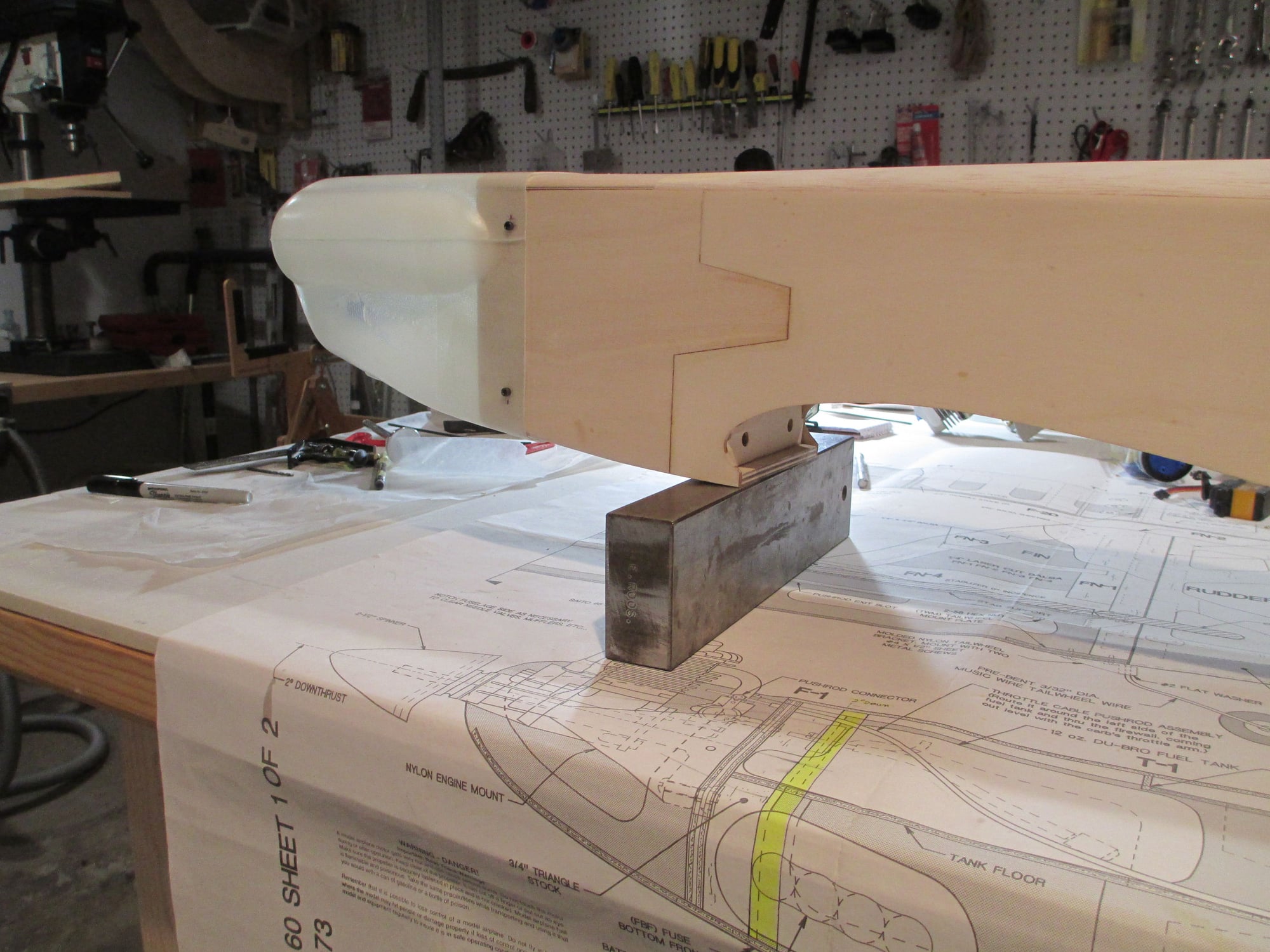
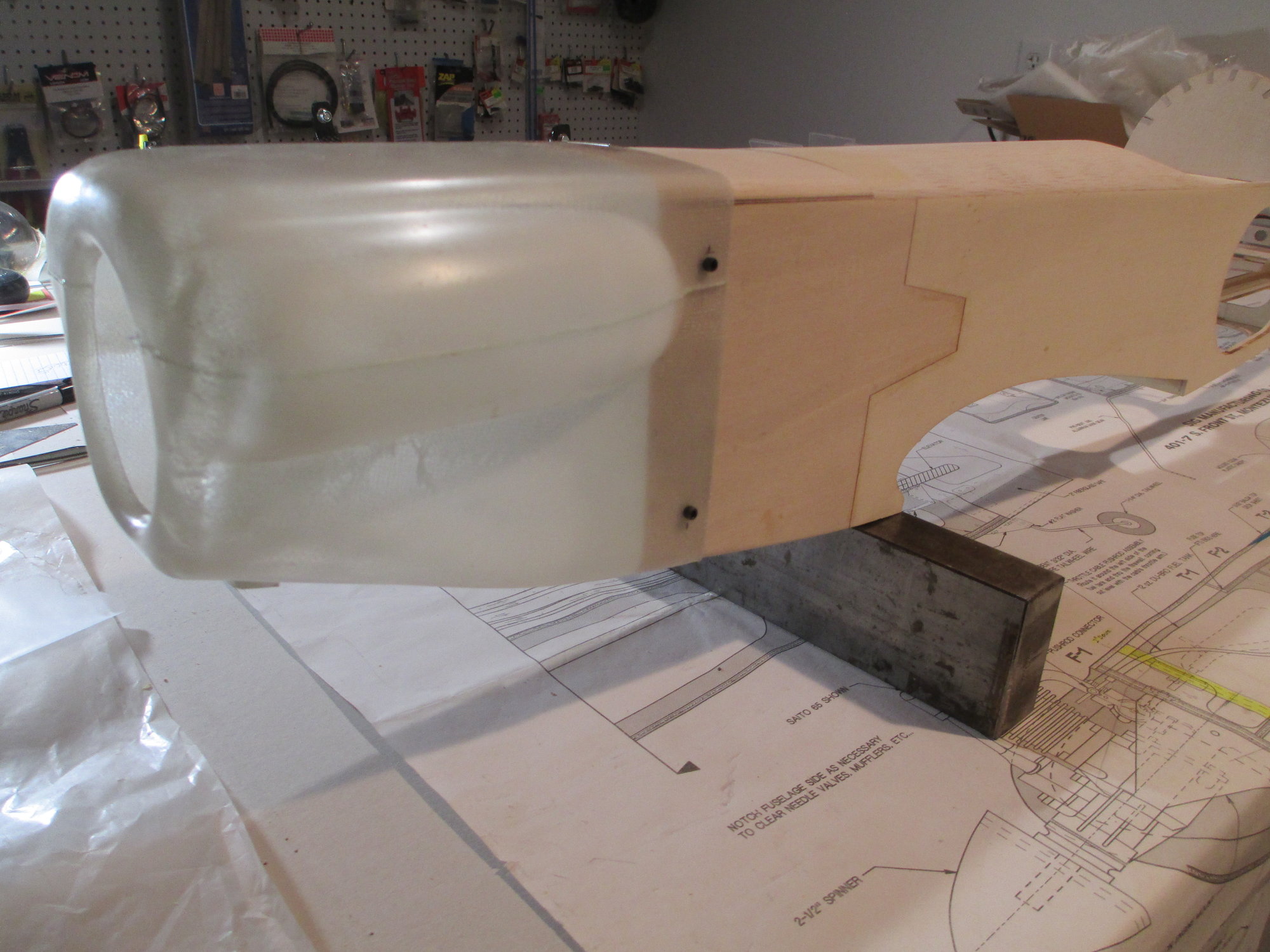
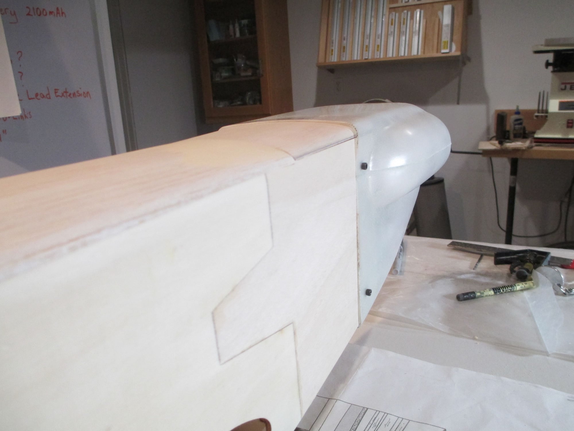
In case you're wondering why I epoxied this odd shaped block to the front of the wing...
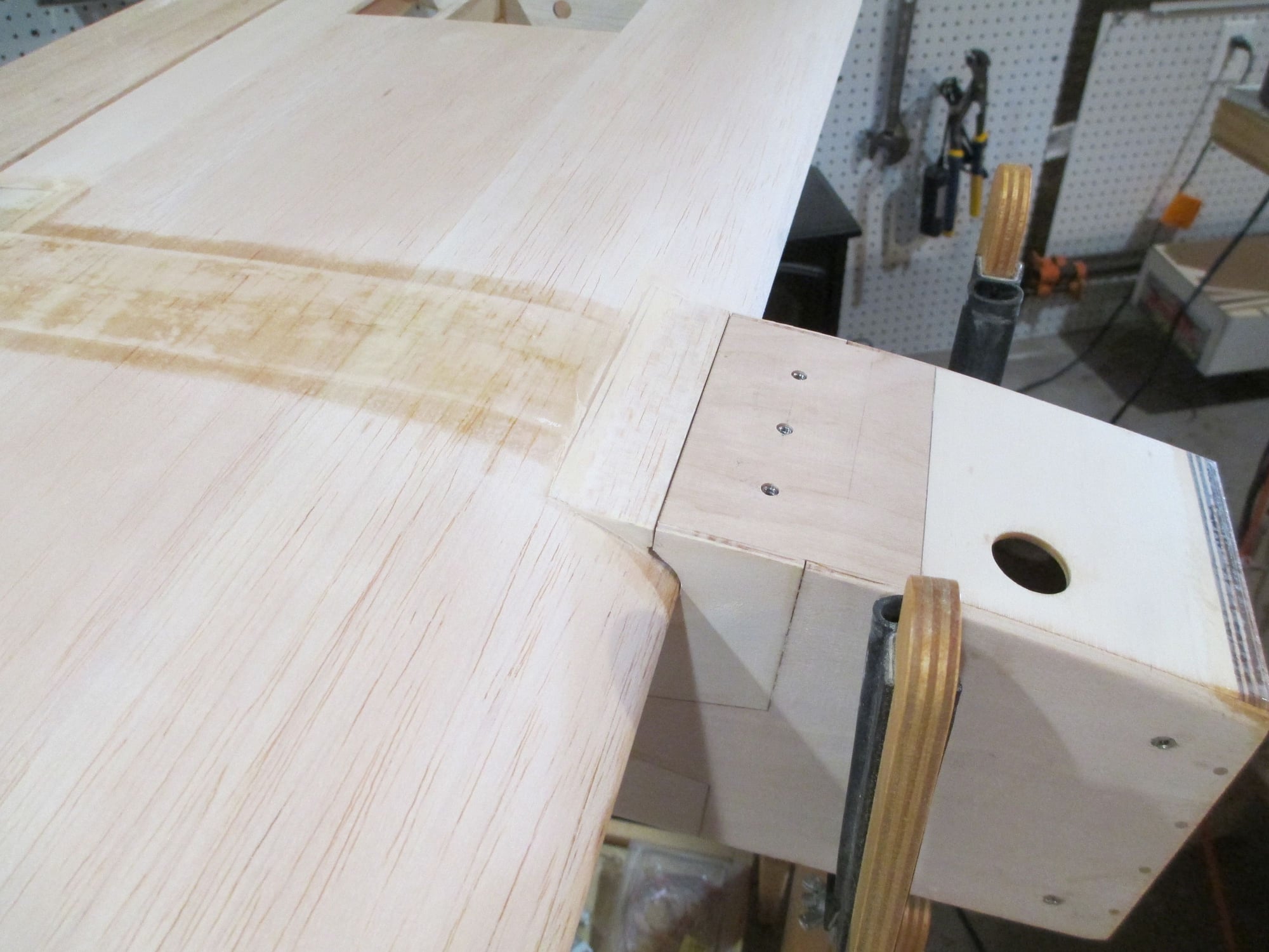
The plans didn't call for this block, but I didn't like the transition from the fuselage to the wing so I took the liberties to add this...
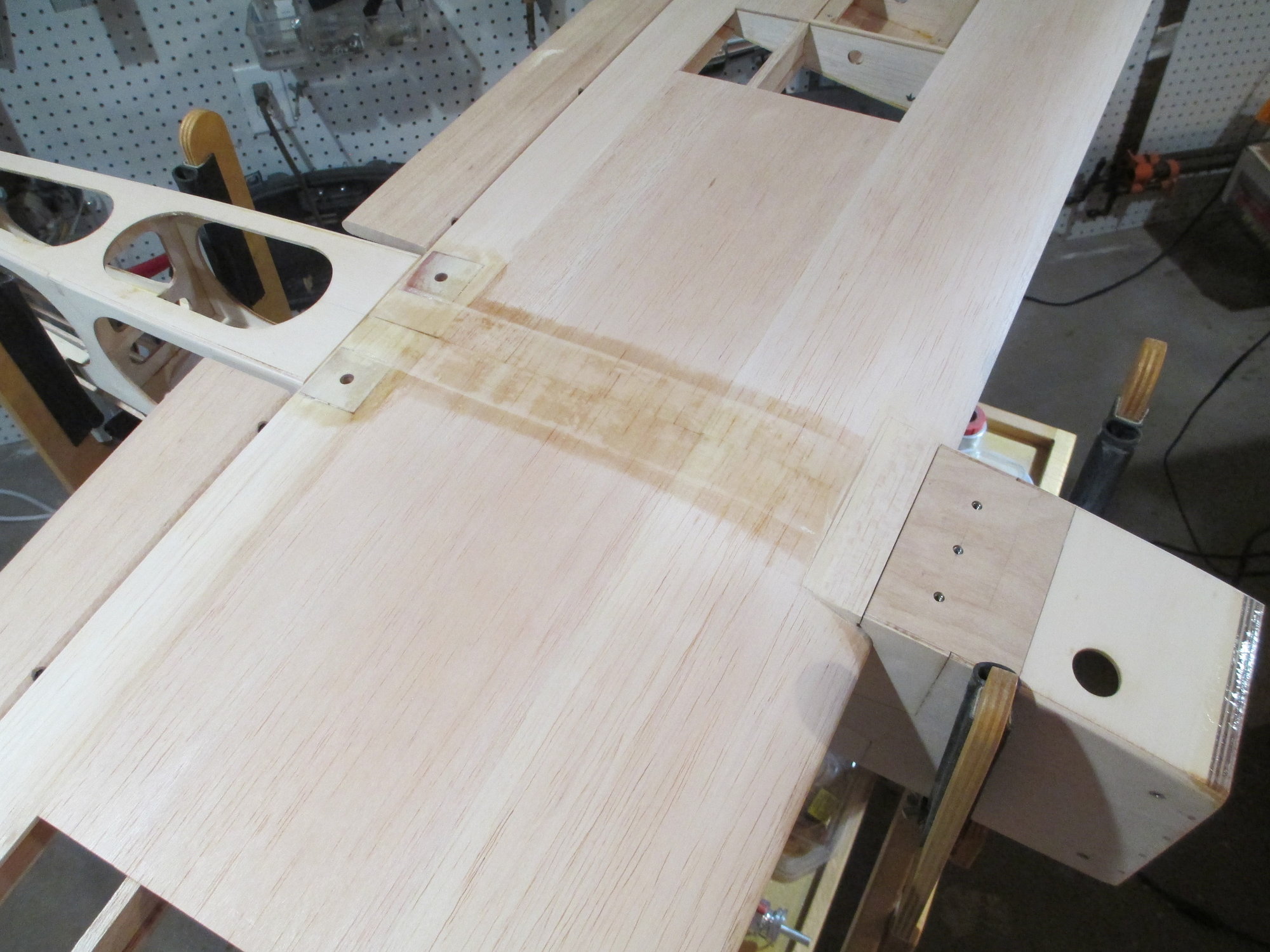
I think it looks much better than without.
Both wing tips have been shaped and glued to the last wing rib.
It's easy to shape one wing tip, but a bit more difficult to make the next one the same size and shape as the first.
In case you're wondering why I epoxied this odd shaped block to the front of the wing...
The plans didn't call for this block, but I didn't like the transition from the fuselage to the wing so I took the liberties to add this...
I think it looks much better than without.
Last edited by VincentJ; 05-06-2019 at 12:50 AM.
05-05-2019, 06:38 AM
#145
Not sure if it would make a difference here or not but the theory is that leaving them squared off will give a bit better control feel just off center. I have tried it on my aerobatic models and it does seem to work. One of those 6 over here or half dozen over there type of things. Looking forward to seeing your project complete. Can't wait to see what colors you are going to use.
05-05-2019, 02:30 PM
#146
Thread Starter
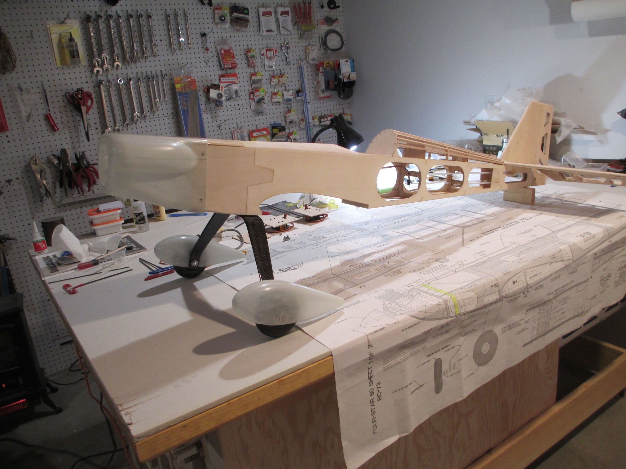
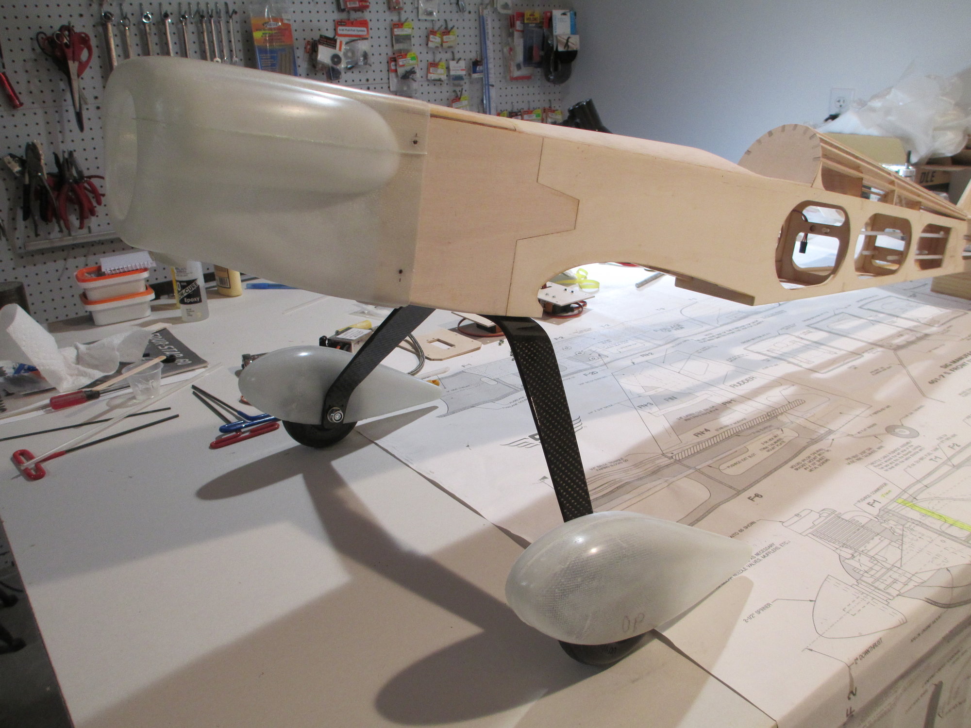
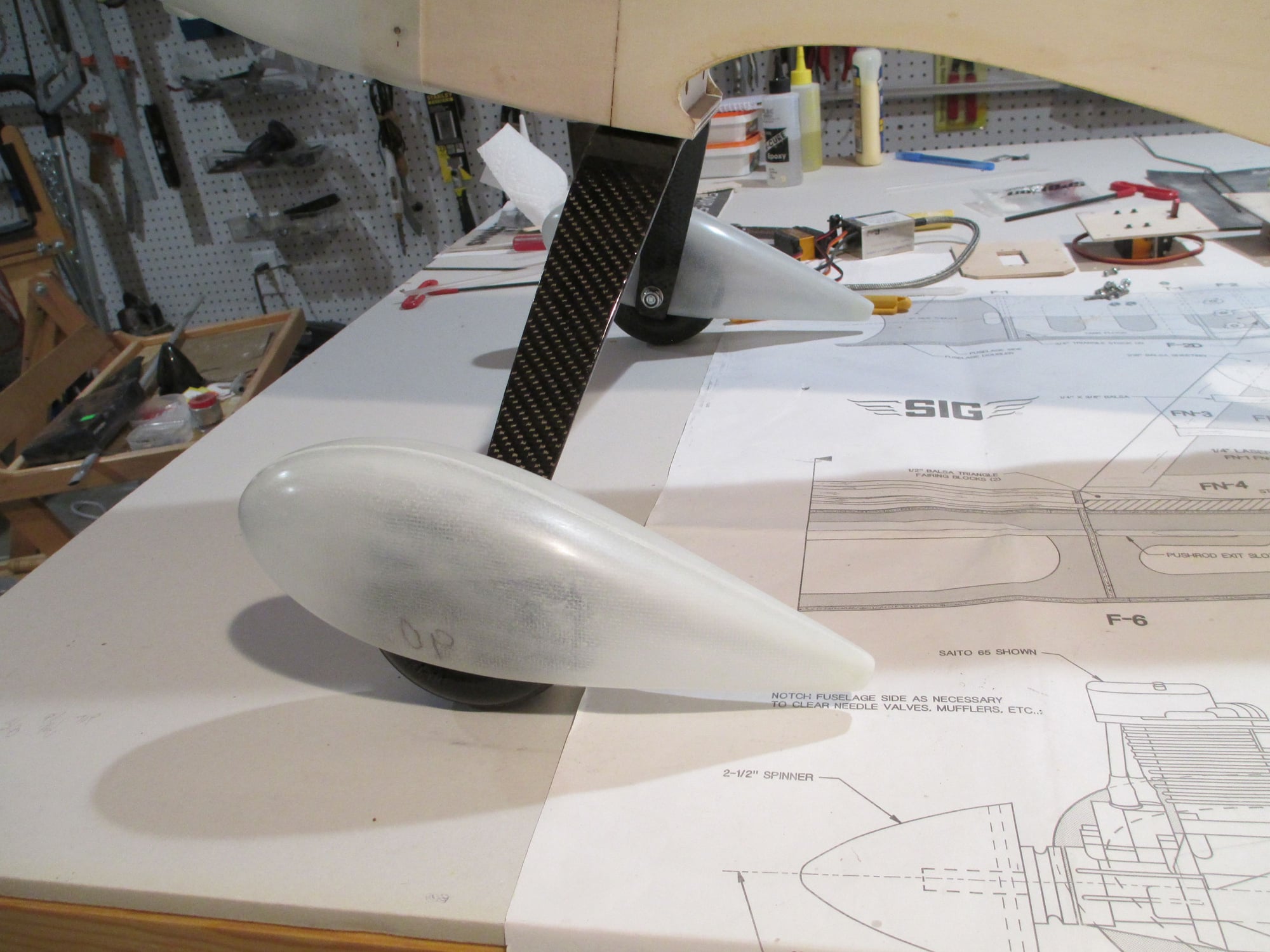
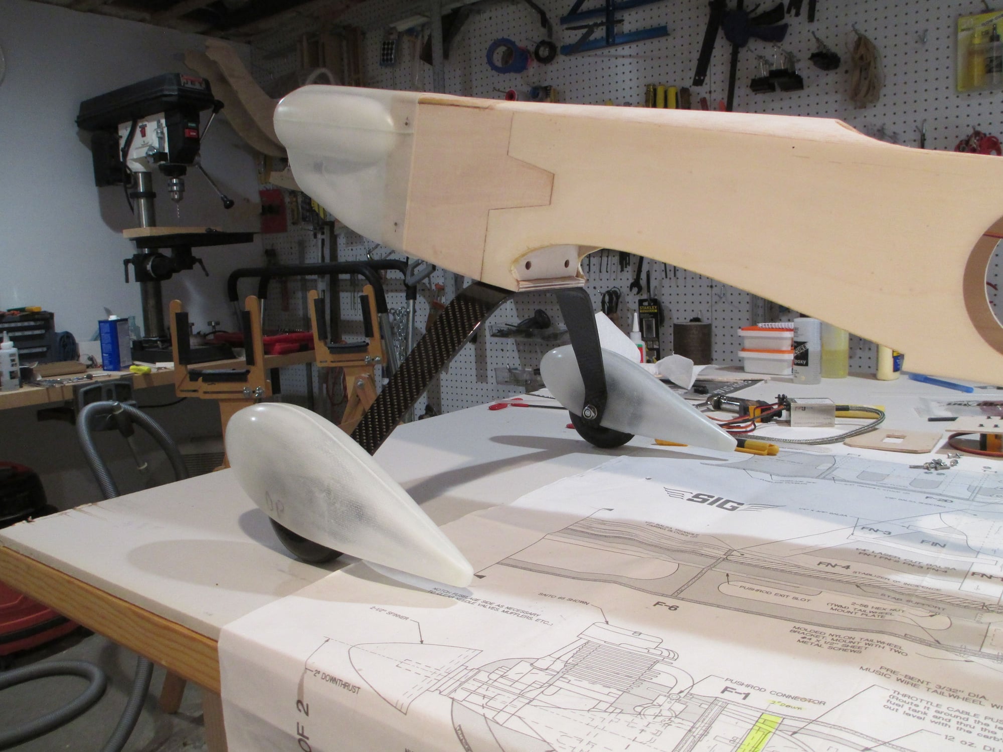
Few shots of the wheel pants... Though not visible in the picture, each pant is secured to the CF landing gear with two 2-56 cap head screws threaded through on the back.
Last edited by VincentJ; 05-06-2019 at 01:00 AM.
05-06-2019, 12:55 AM
#147
Thread Starter
Not sure if it would make a difference here or not but the theory is that leaving them squared off will give a bit better control feel just off center. I have tried it on my aerobatic models and it does seem to work. One of those 6 over here or half dozen over there type of things. Looking forward to seeing your project complete. Can't wait to see what colors you are going to use.

Picking the colors are easy, all of my planes are red and white...
 05-07-2019, 08:05 AM
#148
I'm thinking that with full scale that efficiency and cost of operation is at the top of the priority list. The fat trailing edges do produce drag. On our models there is bad drag and good drag. Full scale also have counter balanced control surfaces where most models don't. A razor sharp trailing edge is more prone to flutter as well. Now will it make any difference on your airplane? Hard to say. If it does it will be very small.
05-08-2019, 05:20 AM
#149
Thread Starter
Just a quick update as to what's going on. The fuselage has been sanded using first 220 grit paper, then final sanded with 400 grit paper. The firewall and removable top hatch have been primered and are now awaiting color. I'm in the process of prepping all of the fiberglass components (cowl and wheel pants) so they can be primered as well, that way everything can be color sprayed at the same time. Pictures will be taken as soon as the color is sprayed.
Pivotal game #5 for the Celtics is on tonight, so not much is going to happen tonight...
Pivotal game #5 for the Celtics is on tonight, so not much is going to happen tonight...
05-11-2019, 05:09 AM
#150
Thread Starter
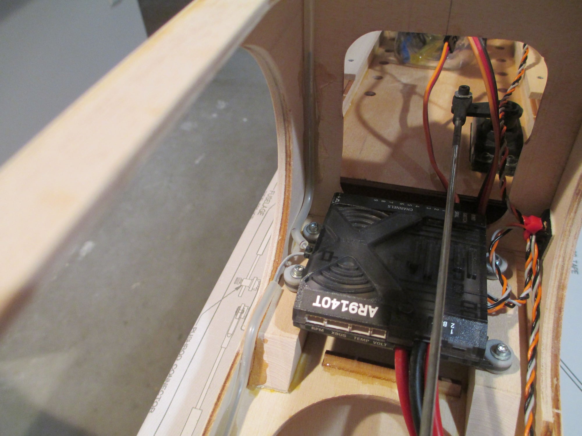
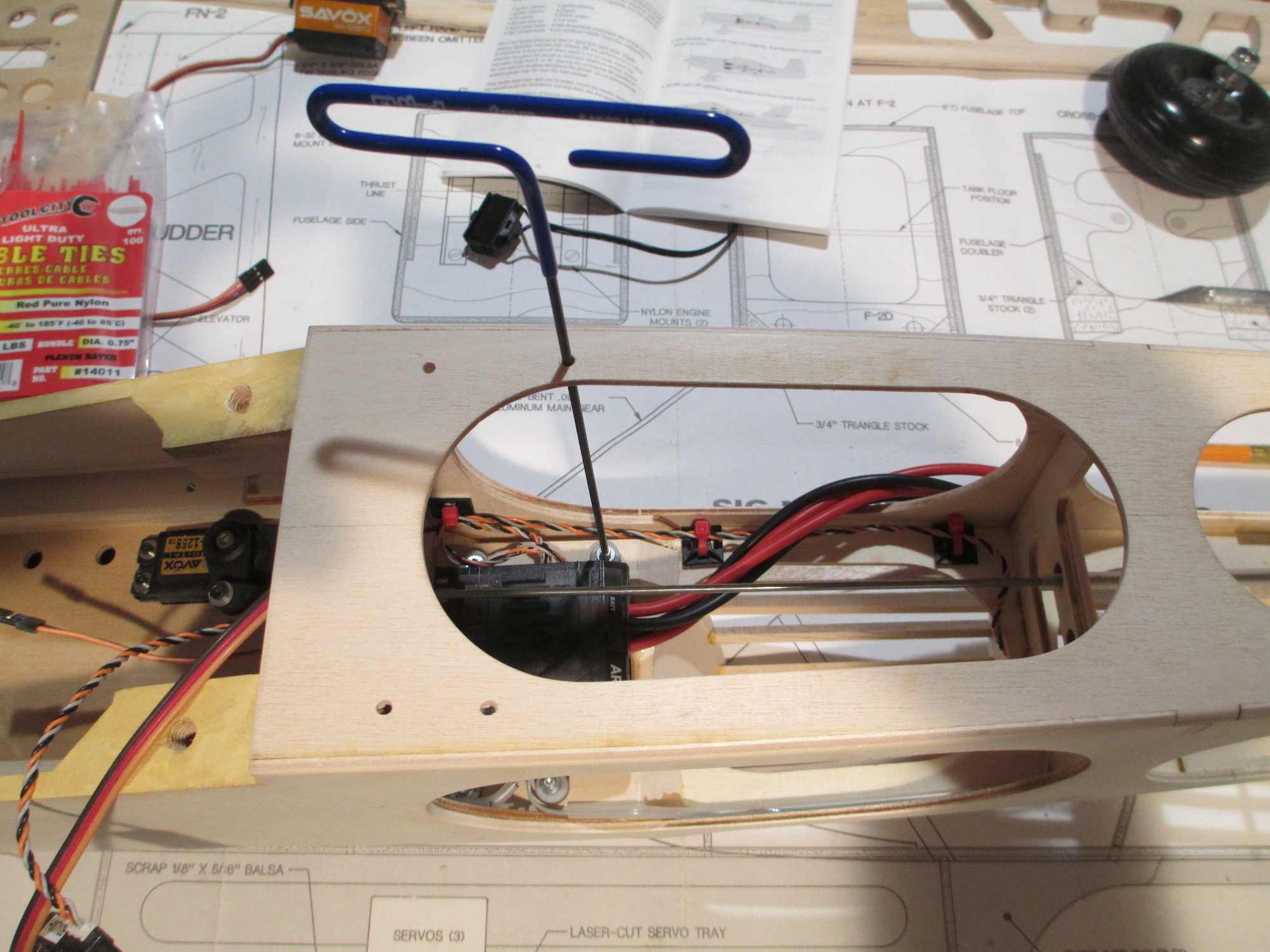
Decided to install the receiver in place. Take note how I kept the antennas in place by slipping them through nylon tubes that I bent to shape using a hot air gun.
This will ensure that the antennas will never move.
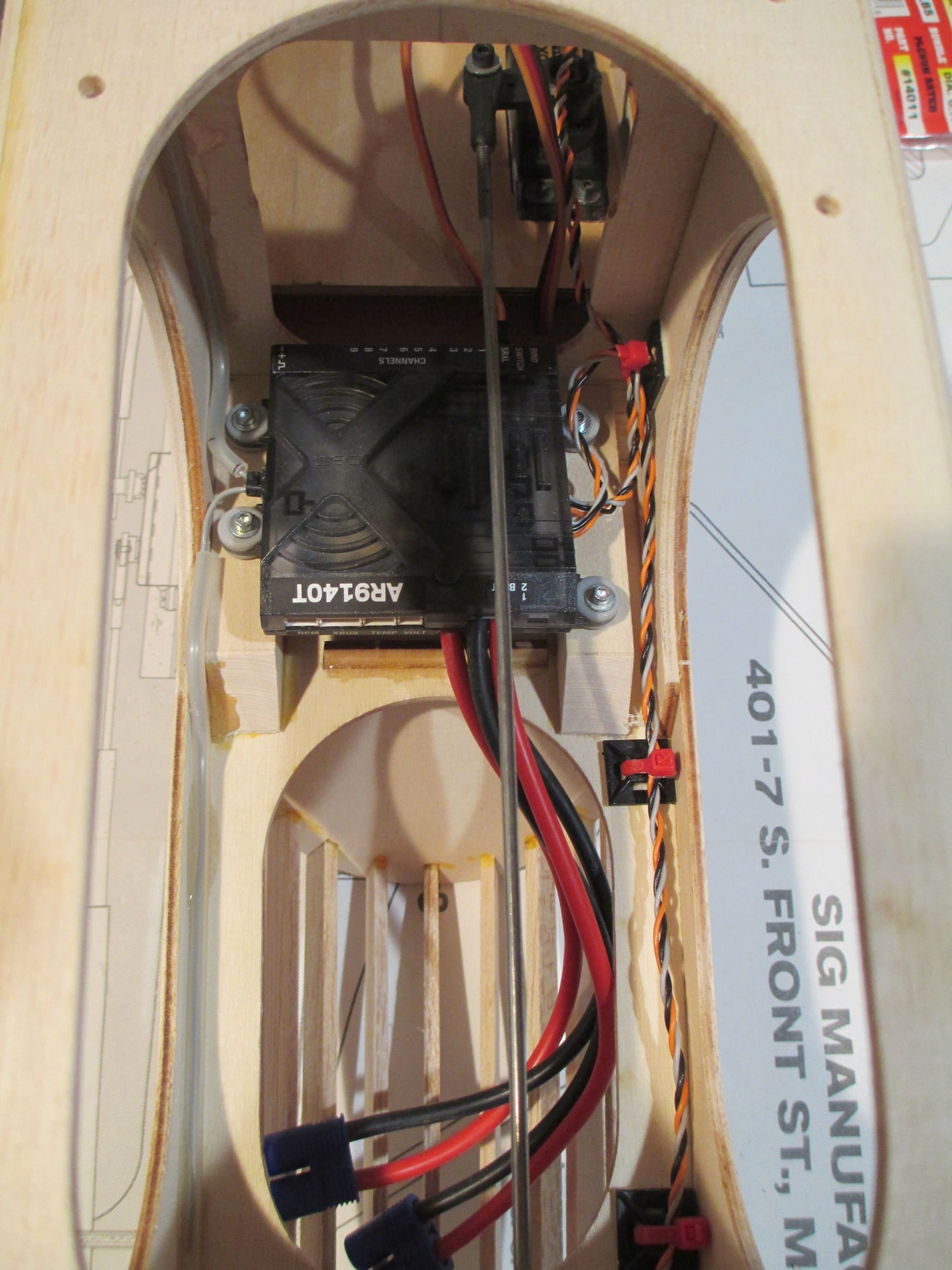
This receiver has the capability to run three remote antennas, however I will only be using two.
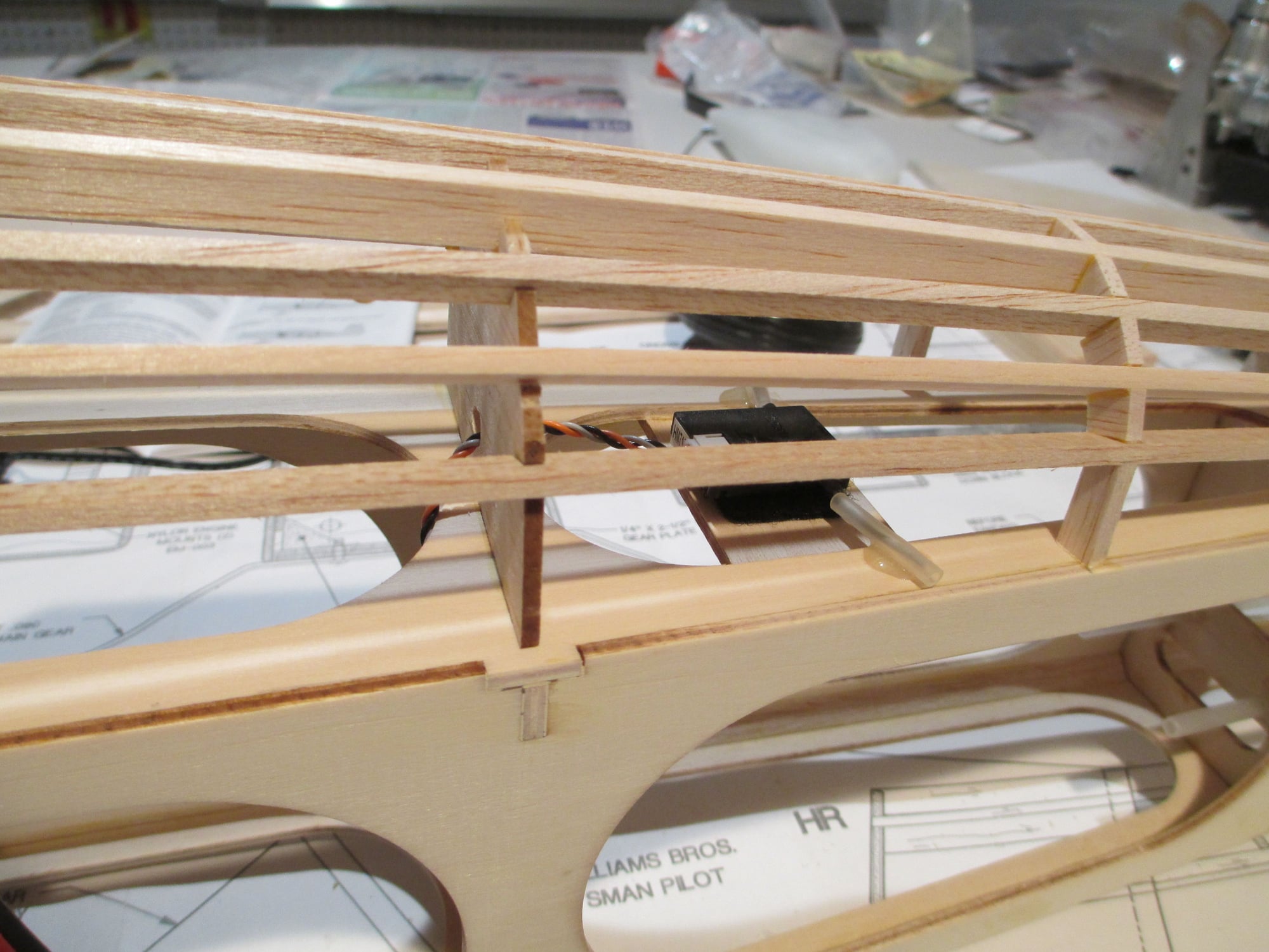
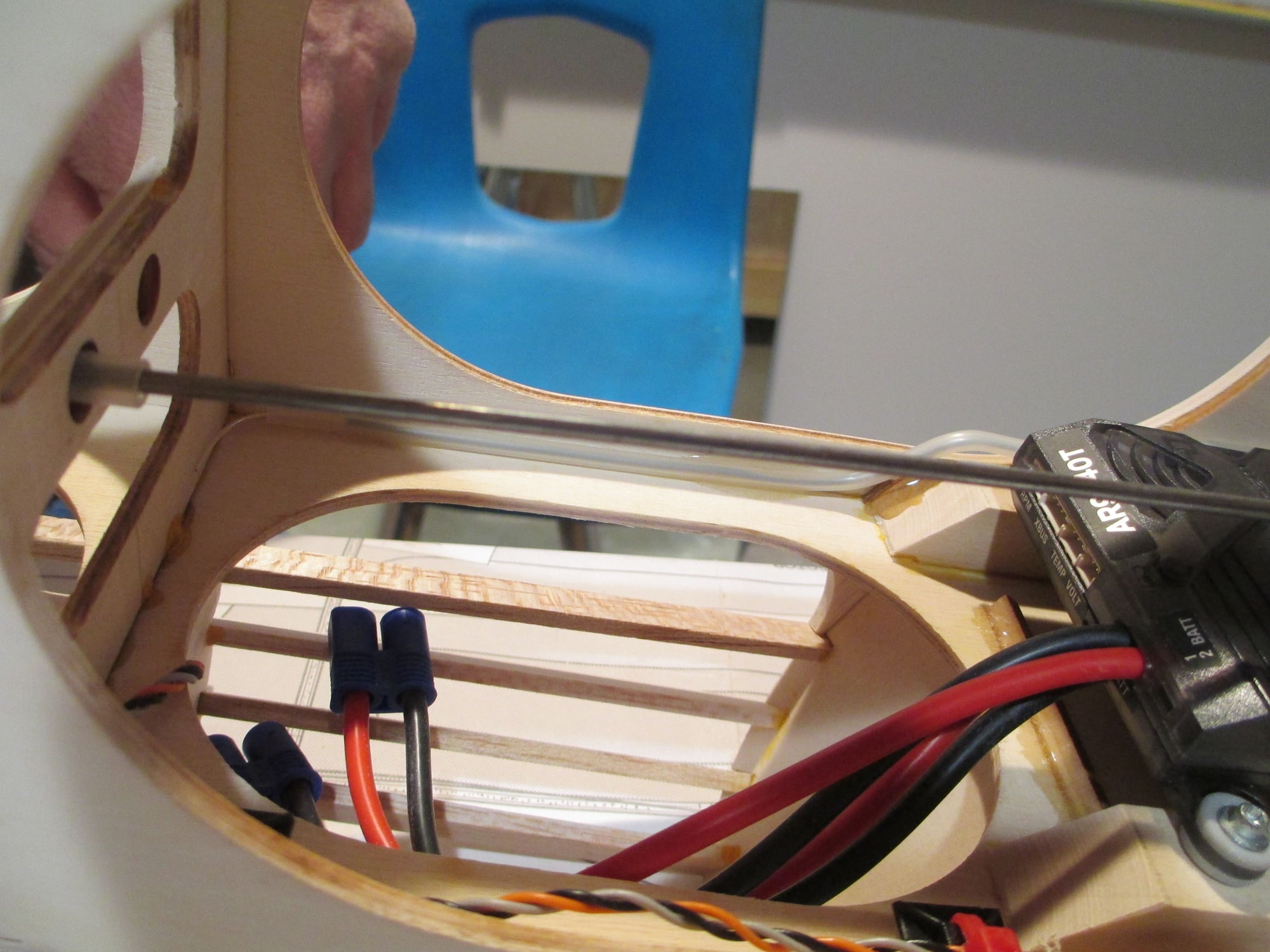
This is where the rear antenna is located, within the safety of the turtle deck.
In the event I need to remove the receiver for whatever reason, four holes were drilled through the bottom of the fuselage that align with the receiver screws. These will be covered over and if/when necessary, the four holes will be cut through the covering to have access to the screw heads.
Last edited by VincentJ; 05-11-2019 at 06:24 AM.