


Scale finishing my BVM Hun
 05-30-2020, 09:15 AM
#176

Join Date: Mar 2004
Location: RAF Lincolnshire, UNITED KINGDOM
Posts: 202
Likes: 0
Received 1 Like
on
1 Post
I put one of these BVM F100's for a friend and found the noseleg doors when hinged as per the manual interfered with the nosewheel tyres during the cycling so I scrapped that method in favour of using offset hinges. This solved the problem and enabled the nose strut to cycle with clearance either side of the tyres.
 06-01-2020, 09:50 PM
#177

My Feedback: (13)
IB
ive heard the same thing which is why I widened the nose door opening when I cut it. That required taking the nose door they give you, belt sanding off the fiberglass �outer skin� so I could glue the interior molded part of the door onto the bottom skin of the fuse before cutting out the new door 1/4� wider
Today was all filling and sanding filling and sanding the hatch and canopy area. Several times I wanted to just call it good and walk but kept going back. It�s prettt good joe but I envy the guys that get it right on the first or second try


Here is the hatch once it was done before primer. Of note the back of the canopy was about 1/16� lower than hatch so I faired it in. You can see how much it took and how far I extended to make it look right
ive heard the same thing which is why I widened the nose door opening when I cut it. That required taking the nose door they give you, belt sanding off the fiberglass �outer skin� so I could glue the interior molded part of the door onto the bottom skin of the fuse before cutting out the new door 1/4� wider
Today was all filling and sanding filling and sanding the hatch and canopy area. Several times I wanted to just call it good and walk but kept going back. It�s prettt good joe but I envy the guys that get it right on the first or second try
Here is the hatch once it was done before primer. Of note the back of the canopy was about 1/16� lower than hatch so I faired it in. You can see how much it took and how far I extended to make it look right
06-13-2020, 08:26 PM
#178
My Feedback: (13)
I�ve been in my own person sand/fill/sand/fill hell lately. Primary focus has been on blending the forward and aft fuse sections. I�m thinking the my only made one aft fuse rhat was carved from the D model forward fuse. The F seems to be a bit off and I�m terrible at that blending thing. I can get it but it takes 6-9 iterations where the masters have it in one or two applications
as a distraction I chose to work on the rudder. Those little sub ribs are supposed to be 3/32 wood but I chose to use .015 poly ply instead as it was easier to finish at looked more scale...but ten percent side!?!? Ugh

Prior to sanding

Sanded side
as a distraction I chose to work on the rudder. Those little sub ribs are supposed to be 3/32 wood but I chose to use .015 poly ply instead as it was easier to finish at looked more scale...but ten percent side!?!? Ugh
Prior to sanding
Sanded side
08-05-2020, 06:33 AM
#179
My Feedback: (13)
The sand/fill hell continues. I�ve set the forward fuse aside as done and ready for paint. That includes the hatch, canopy, gear doors and speed brake.
ive moved on to the aft fuse and am finding that the vertical is not as wide as the base of the vertical on the aft fuse. The other thing I�ve found is a number of voids in the primer or glass from the factory around the vertical. I�ve not done much layup work but I�m thinking the small area with the very shard angles makes that process very difficult. So I�ve been filling and sanding and blending and and and... it�s coming along. It�s just slow

Base of the fin with the Dolphin Glaze to get the width at the bottom right. If you look close you can see pencil swirls in the glazed area. A buddy saw that and asked if I was doodling on my plane. Technique here: I put swirls where I need more filler and Xs where I need to sand. Too many times I mix filler up and can�t remember all the spots I was supposed to do or I go to prime and find a high spot I should have gotten but forgot

Other side very early on
ive moved on to the aft fuse and am finding that the vertical is not as wide as the base of the vertical on the aft fuse. The other thing I�ve found is a number of voids in the primer or glass from the factory around the vertical. I�ve not done much layup work but I�m thinking the small area with the very shard angles makes that process very difficult. So I�ve been filling and sanding and blending and and and... it�s coming along. It�s just slow
Base of the fin with the Dolphin Glaze to get the width at the bottom right. If you look close you can see pencil swirls in the glazed area. A buddy saw that and asked if I was doodling on my plane. Technique here: I put swirls where I need more filler and Xs where I need to sand. Too many times I mix filler up and can�t remember all the spots I was supposed to do or I go to prime and find a high spot I should have gotten but forgot
Other side very early on
Last edited by ozief16; 08-05-2020 at 06:39 AM.


 08-18-2020, 12:50 PM
#182
My Feedback: (13)
Ha! Sorry Craig. I typed a whole thing out and computer hiccuped and dropped it so the second one was much shorter and more confusing I�m sure
A few posts ago Rav said he had an issue with stock nws servo mounting position where it prevented the nose from coming down as the Nw got hung up on the cables. He suggested moving the servo back to where I have it shown.
At the time i posted I was really asking about the left right of the whole thing (ie spline centered vs servo centered). Not I�m thinking about mounting it an inch or so higher to further deconflict it from the dual nose wheels. Redman suggested angling the servo down a bit so ball links won�t want to bind
ps-check your email Craig


 11-10-2020, 09:15 PM
#188
My Feedback: (13)
Guys the sweat shop continues. Life has been busy (good problem to have right now) so the isn�t done but continues on
today I scribes the panel lines into one of the slats/flaps/ailerons and glued the pitot tube base on

Here is the slat. The double layer of masking tape is something to run the dremel cutoff wheel glued to square stock something to run back and forth

Getting the pitot tube base glued on. The molding is slightly off so make sure you align to the centerline of the Jet
today I scribes the panel lines into one of the slats/flaps/ailerons and glued the pitot tube base on
Here is the slat. The double layer of masking tape is something to run the dremel cutoff wheel glued to square stock something to run back and forth
Getting the pitot tube base glued on. The molding is slightly off so make sure you align to the centerline of the Jet
 05-20-2021, 07:14 PM
#190
My Feedback: (13)
Sorry for the delay guys, lots of life happening right now. Most of my modeling time has gone to the new BVM PNP F-100. I got one of the first in the states so I�d call it a quasi-preproduction model. Some little things needed sorting and then I had to hang some stuff off it. It needs a healthy dose of weathering yet but I wanted back onto the kit
I started the painting process by laying down a silver base layer to chip/burnish back to depending on where it is in the plane or in the cockpit. I�ve also found myself intently studying FS cockpits to see where stuff is worn vs chipped. Ie it�s way more chipped up on the left side than the right...of course as that�s where you climb in and where most wear their watches etc


I started the painting process by laying down a silver base layer to chip/burnish back to depending on where it is in the plane or in the cockpit. I�ve also found myself intently studying FS cockpits to see where stuff is worn vs chipped. Ie it�s way more chipped up on the left side than the right...of course as that�s where you climb in and where most wear their watches etc
Last edited by ozief16; 05-20-2021 at 07:25 PM.
The following users liked this post:
jcterrettaz (05-20-2021)
05-20-2021, 07:36 PM
#191
My Feedback: (13)
I thought I had pics of the silver painting on the kit but I guess not. I�m sure you can imagine...
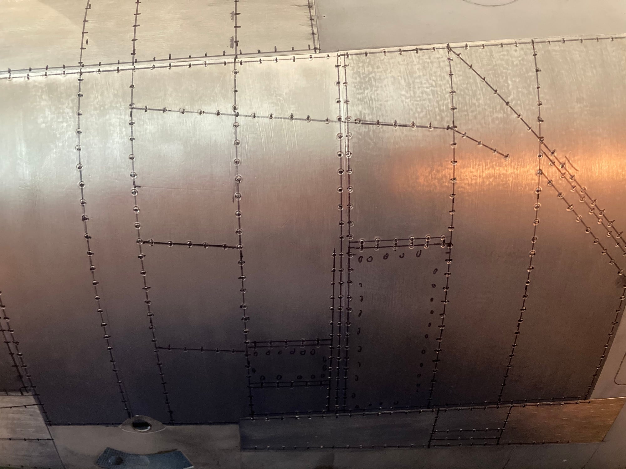
One of the biggest areas of concern for me since starting the project was the hot section. We all know Huns have widely varied hot sections so I believe you could do about anything and be ok. Since I was going for a Vietnam warhorse rather than a show pony, I struggled with how dirty to make it, base colors, etc etc. I experimented with silver paint and Flite Metal underlayment, then painting over it and burning it away with heat or a buffing wheel. I didn�t like that so ended up doing FM with paint over the top. Though I don�t intend to rivet the whole model I do think the rivets in the hot section really stand out so they had to be replicated. Thankfully there�s a FS Hun where I work so I got a bunch of detailed pics one day and then laid the rivet lines out with a sharpie. Once I knew where they needed to be I made a few little tools to cut them into the FM. The tools were simply a small length of dowel for grip with a piece of aluminum tube glued into them that I sharpened and blammo...rivets. A little alcohol took the sharpie off and the result was stunning. I really hated to cover up the pristine FM with rivets but again...warhorse.

Laying out FM

Rt side rivet layout (yes left and right are different!)

Left side


One of the biggest areas of concern for me since starting the project was the hot section. We all know Huns have widely varied hot sections so I believe you could do about anything and be ok. Since I was going for a Vietnam warhorse rather than a show pony, I struggled with how dirty to make it, base colors, etc etc. I experimented with silver paint and Flite Metal underlayment, then painting over it and burning it away with heat or a buffing wheel. I didn�t like that so ended up doing FM with paint over the top. Though I don�t intend to rivet the whole model I do think the rivets in the hot section really stand out so they had to be replicated. Thankfully there�s a FS Hun where I work so I got a bunch of detailed pics one day and then laid the rivet lines out with a sharpie. Once I knew where they needed to be I made a few little tools to cut them into the FM. The tools were simply a small length of dowel for grip with a piece of aluminum tube glued into them that I sharpened and blammo...rivets. A little alcohol took the sharpie off and the result was stunning. I really hated to cover up the pristine FM with rivets but again...warhorse.
Laying out FM
Rt side rivet layout (yes left and right are different!)
Left side
The following users liked this post:
Halcyon66 (08-02-2021)
05-20-2021, 07:43 PM
#192
My Feedback: (13)
Here is the finished product. It struck the balance of leaving the rivet handiwork showing while still looking like a slightly neglected machine of war

Before any paint


Steel alclad and the burned metal (goldish color in back)

Starting to lay the blues and reds

Finished product left


Bottom

Right

Finished right
Before any paint
Steel alclad and the burned metal (goldish color in back)
Starting to lay the blues and reds
Finished product left
Bottom
Right
Finished right
Last edited by ozief16; 05-20-2021 at 07:47 PM.
05-20-2021, 09:39 PM
#193
Outstanding some of the best backend F-100 work I have ever seen.
I got one of these back in 2001, the great BV delivered it to me at Top Gun.
Regards,
I got one of these back in 2001, the great BV delivered it to me at Top Gun.
Regards,

 05-22-2021, 07:57 PM
#197
My Feedback: (13)
When I was looking at the pics I took of the FS I noticed some other panels around the plane that stood out too so, being a bit obsessed, I started those in FM with screw head detail too. I�ll simply paint over these panels so they�re there just for texture


 07-24-2021, 07:18 PM
#199
My Feedback: (13)
Guys, I�ve been at it with the plane but have been terrible with the posting
i ended up having contractor issues where I had to stay at the house while my wife took the kids to the beach. Long week for both of us but I chose to use it get the painting going. There�s a FS at Nellis that I looked at really closely. The stock FS numbers for the paint colors weren�t even close to what a sun-beaten airplane looked like. I made up sheets where I cut the stock colors 10/20/30% etc with white paint and came to an interesting, but predictable conclusion: the tan faded less than the light green which faded less than the dark green. Of course the darker the color the higher the fade. I ended up on tan being cut with 30% white, light green 40% and dark green 50%. I know the numbers sound high but when compared to an actual plane in the sun the model is still darker. At first I thought the colors looked a little cartoonish but after some weathering with a scotchbrite pad I really like the results


3M doorjam tape


i ended up having contractor issues where I had to stay at the house while my wife took the kids to the beach. Long week for both of us but I chose to use it get the painting going. There�s a FS at Nellis that I looked at really closely. The stock FS numbers for the paint colors weren�t even close to what a sun-beaten airplane looked like. I made up sheets where I cut the stock colors 10/20/30% etc with white paint and came to an interesting, but predictable conclusion: the tan faded less than the light green which faded less than the dark green. Of course the darker the color the higher the fade. I ended up on tan being cut with 30% white, light green 40% and dark green 50%. I know the numbers sound high but when compared to an actual plane in the sun the model is still darker. At first I thought the colors looked a little cartoonish but after some weathering with a scotchbrite pad I really like the results
3M doorjam tape
Last edited by ozief16; 07-24-2021 at 07:35 PM.
The following users liked this post:
Halcyon66 (08-02-2021)
07-24-2021, 07:19 PM
#200
My Feedback: (13)
The next step was to install a split mini AC unit in my garage. Thankfully my buddy Jason was willing to kill an entire day helping me. Man, what a huge difference it makes�especially in Vegas!!!

Outside before all covers were on

SUPER quiet

Inside unit above the shelf
Outside before all covers were on
SUPER quiet
Inside unit above the shelf
Last edited by ozief16; 07-24-2021 at 07:37 PM.