


IAF-Zukit-Fouga Magister (RCJC)

 03-14-2020, 06:27 AM
#27

Thread Starter
The 2 aluminum duels are placed in 2 hard wood blocks glued to the inner structure. One of the hard wood blocks was not 100% glued to its location. Good thing it happened before flight and it was easy fixed. It also reveled the total good quality of the internal structure.
03-15-2020, 11:12 PM
#29
Thread Starter
Moving on to the fuel system. the kit arrives with 4 fuel tanks. 2 mains saddle type tanks to be located in center section both side of turbine bay, 1 front main to be placed in the bottom front fuselage and one more to be used as liquid for the smoke system.
All necessary clunks and fuel lines are supplied with the kit. I used the supplied Viton fuel lines inside the tanks and used Tygon lines for the entire system.
at this time i skipped installing a smoke system therefore not used the 4th tank.
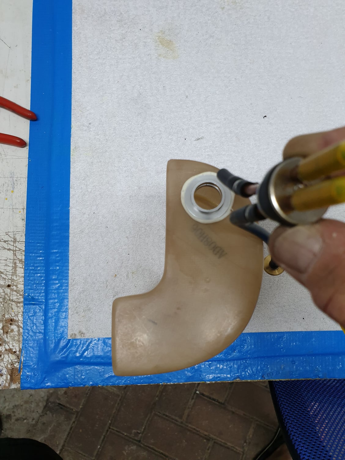
This is before applying safety wire to all lines.
All necessary clunks and fuel lines are supplied with the kit. I used the supplied Viton fuel lines inside the tanks and used Tygon lines for the entire system.
at this time i skipped installing a smoke system therefore not used the 4th tank.
This is before applying safety wire to all lines.
03-15-2020, 11:25 PM
#30
Thread Starter

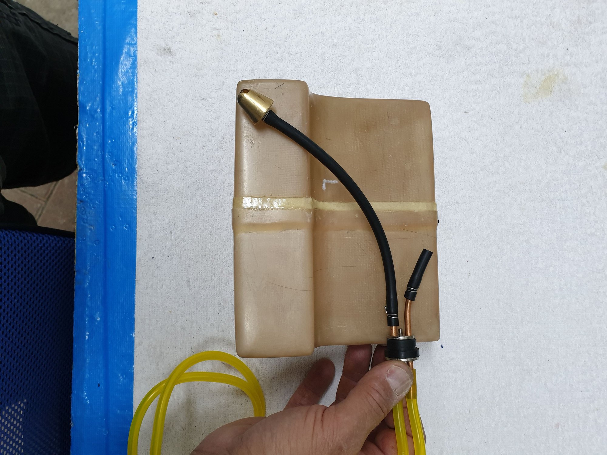
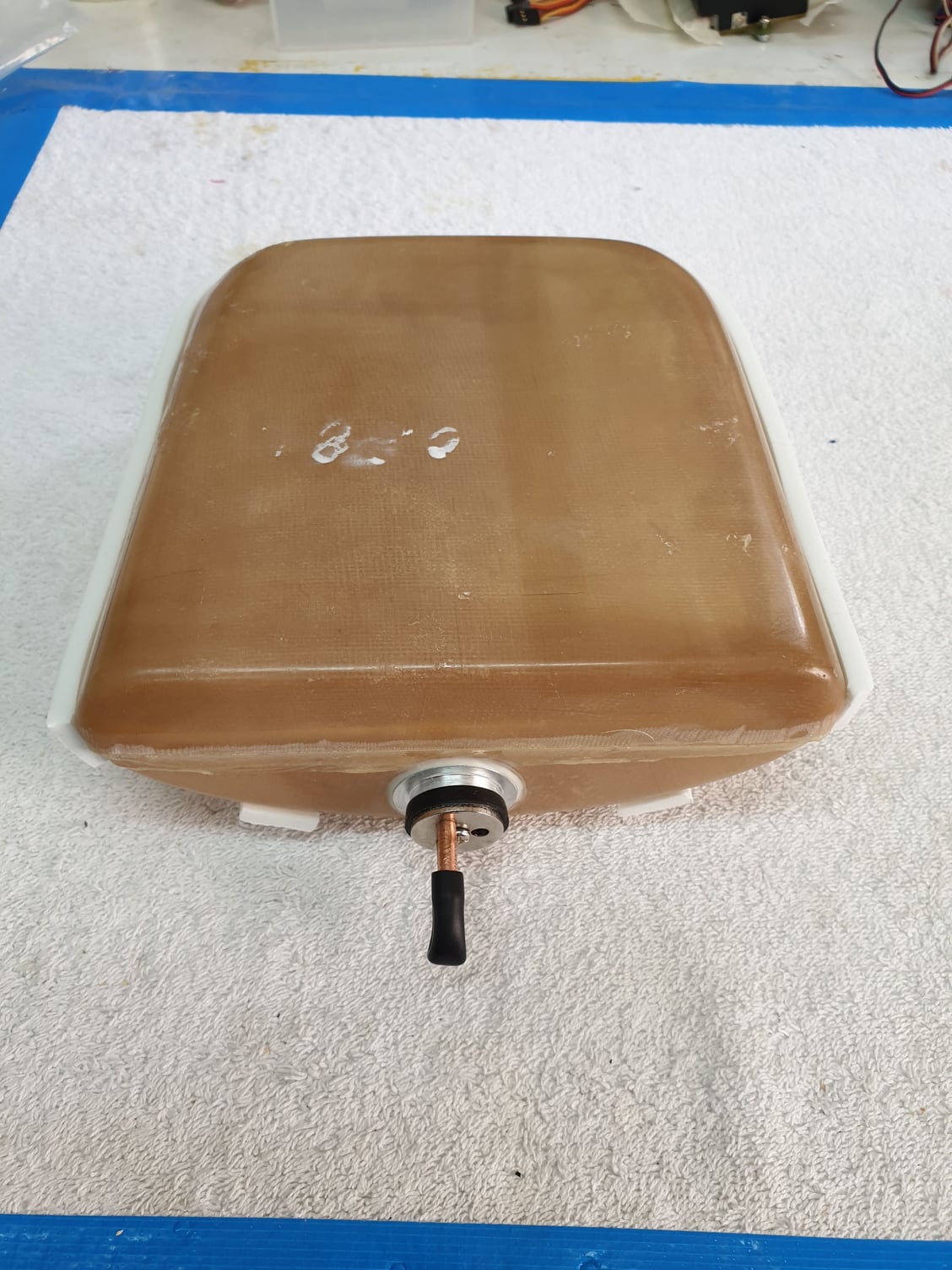
All four tanks where washed with soap water then tested for leaks and volume. In this picture you can see the 3 fuel tanks.
03-15-2020, 11:33 PM
#31
Thread Starter
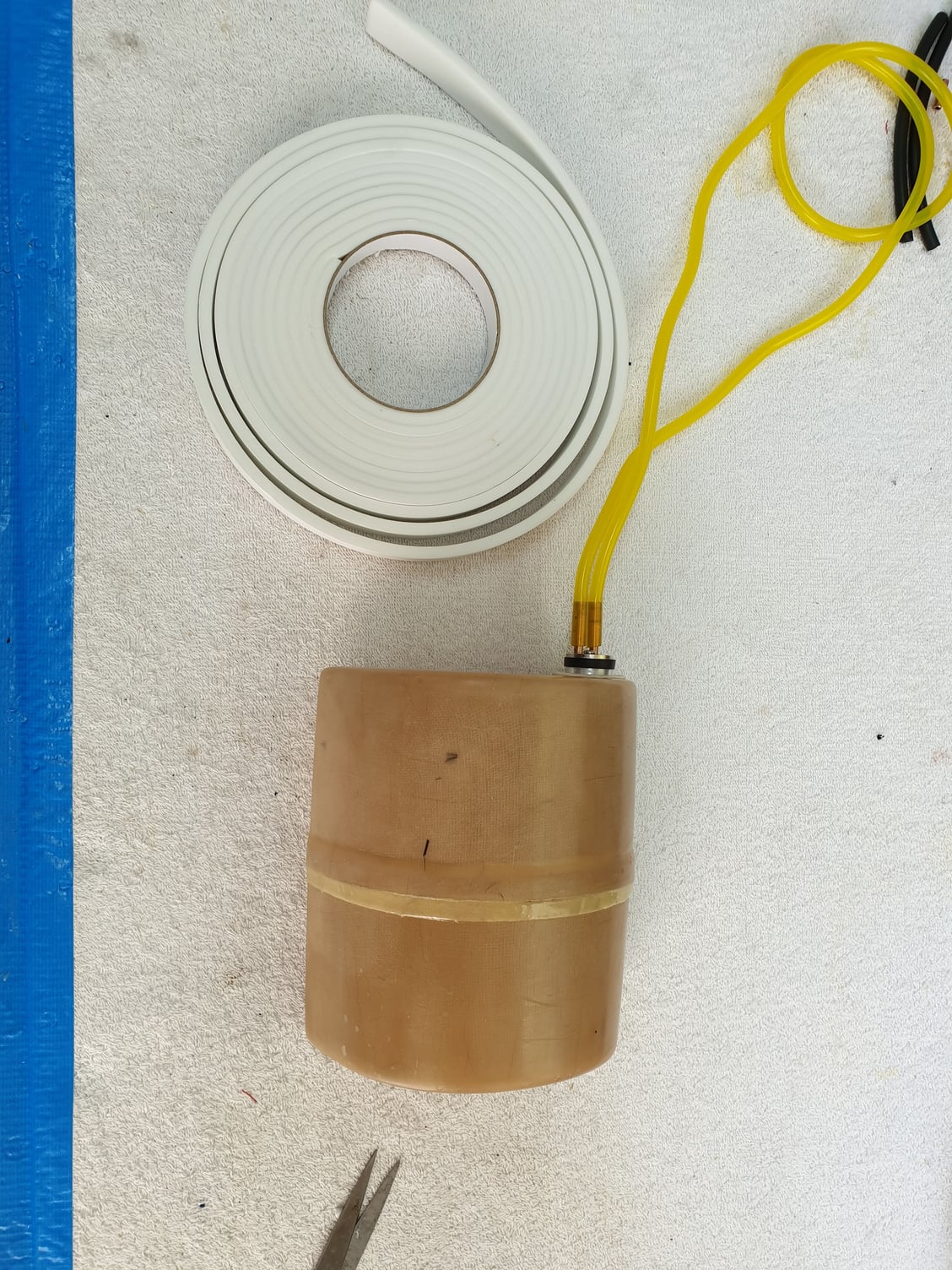
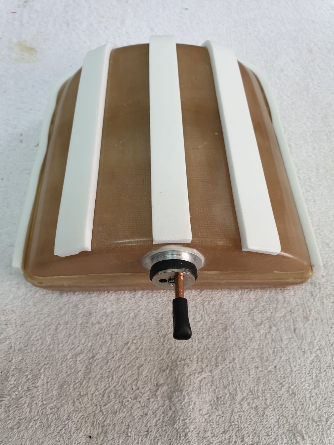
I used foam stripes in all tanks to "cushion" them into place and eliminate any unwanted hard contact to the surface.

Last edited by avi sirota; 03-15-2020 at 11:35 PM.
03-16-2020, 12:06 AM
#32
Moving on to the fuel system. the kit arrives with 4 fuel tanks. 2 mains saddle type tanks to be located in center section both side of turbine bay, 1 front main to be placed in the bottom front fuselage and one more to be used as liquid for the smoke system.
All necessary clunks and fuel lines are supplied with the kit. I used the supplied Viton fuel lines inside the tanks and used Tygon lines for the entire system.
at this time i skipped installing a smoke system therefore not used the 4th tank.
This is before applying safety wire to all lines.
All necessary clunks and fuel lines are supplied with the kit. I used the supplied Viton fuel lines inside the tanks and used Tygon lines for the entire system.
at this time i skipped installing a smoke system therefore not used the 4th tank.
This is before applying safety wire to all lines.
Though personally I would alway use a hi flow felt clunk in tanks like that.
Dave
03-16-2020, 12:11 AM
#33
Thread Starter
Thanks Dave for the input. You are correct. This picture was taken during line length measurements and before all was ready. The line was shortened and the clunk secured with safety wire.
Avi
Avi
03-16-2020, 12:34 AM
#34
Thread Starter
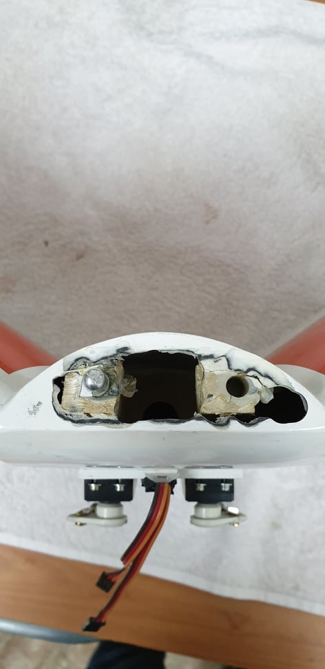
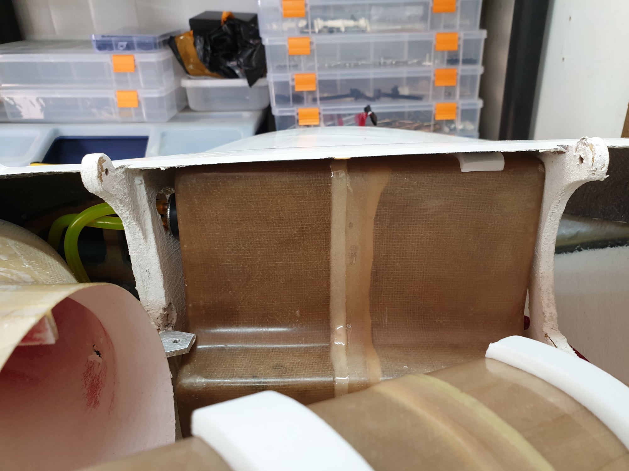
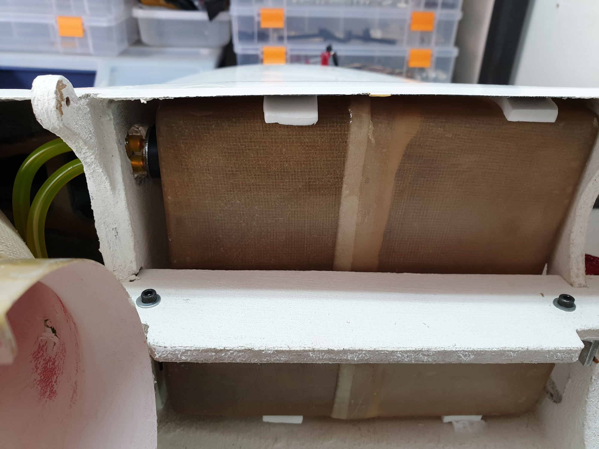
The front main fuel tank is located in bottom fuselage just between the air inlets. I secured it in place by making a "wall" to prevent it from moving and a removable retaining bracket on top of it.
It also have foam stripes.
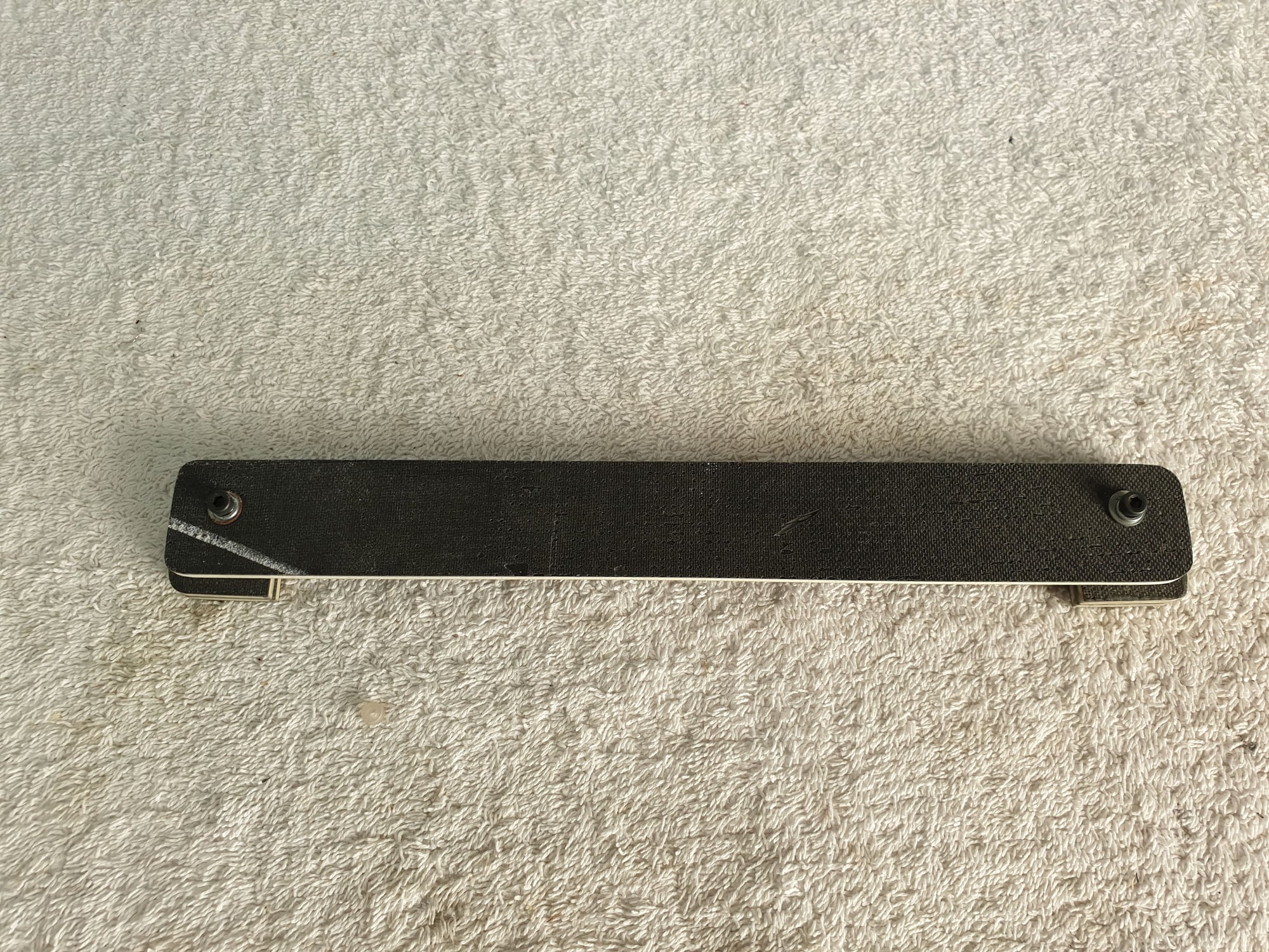
Removable bracket to keep the front main tank in place. Upper view.
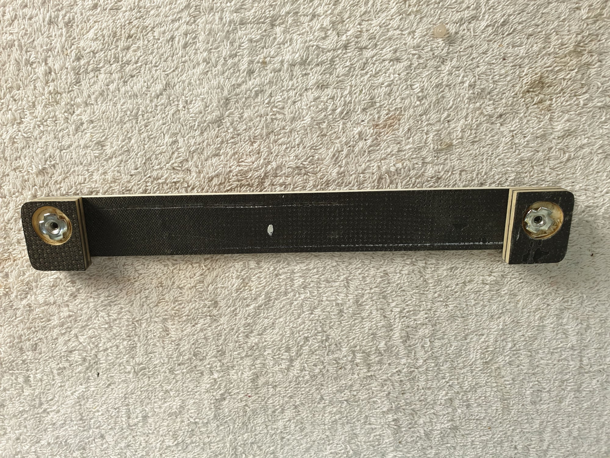
Removable bracket to keep the front main tank in place. bottom view.
The "wall" to retain the front main tank.
Front tank complete arrangement.
It also have foam stripes.
Removable bracket to keep the front main tank in place. Upper view.
Removable bracket to keep the front main tank in place. bottom view.
The "wall" to retain the front main tank.
Front tank complete arrangement.
03-16-2020, 01:12 AM
#35
Thread Starter
Fuel pump and UAT located in place using fixed brackets I created. They needed to be in such height/depth not to interfere with the cockpits floor.
UAT bracket

Fuel pump base bracket
UAT and Fuel pump brackets temporary in place for height/depth measurements.
UAT bracket
Fuel pump base bracket
UAT and Fuel pump brackets temporary in place for height/depth measurements.
03-16-2020, 03:23 AM
#36
Thread Starter
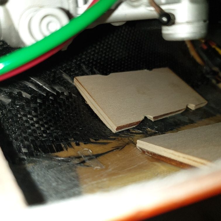
The systems and equipment shelf is made from two 3 m"m parts. Because of the weight added in the rear fuselage due to reinforcement and heat protection treatment and not wanting to add any ballasts for C.G I used a good idea from a fellow modeler (Thanks Ronen) and moved the radio and equipment batteries forward as possible to the nose cone so they could be serviced/removed for charging trough the front gear hatch.
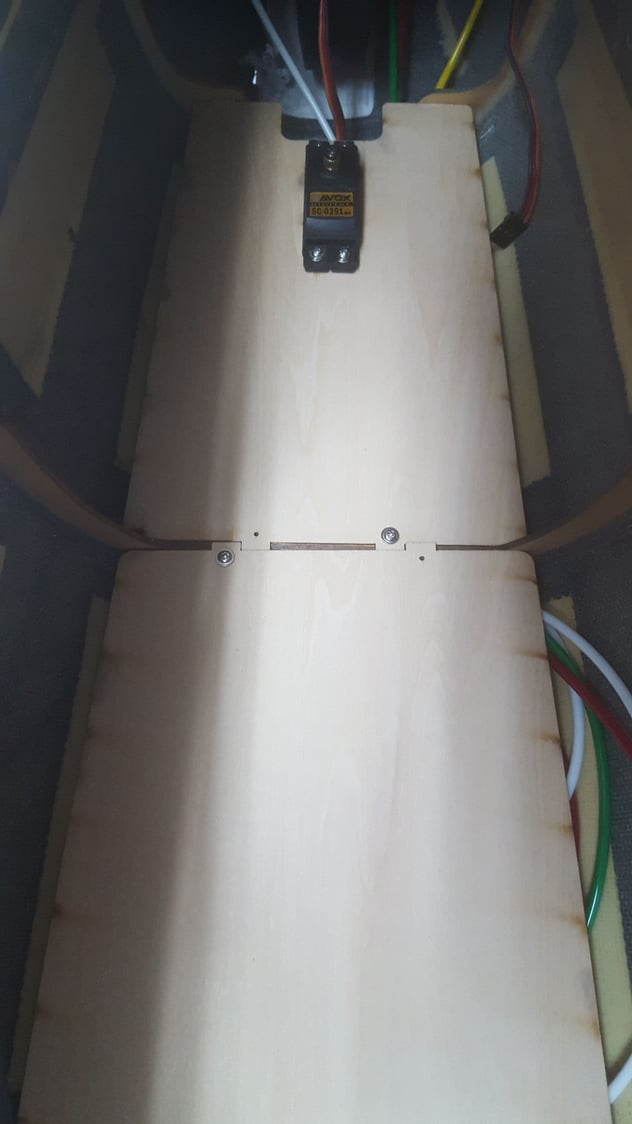
Two parts equipment shelf and the steering servo in it's original location.
The steering servo was placed beneath the front equipment shelf.

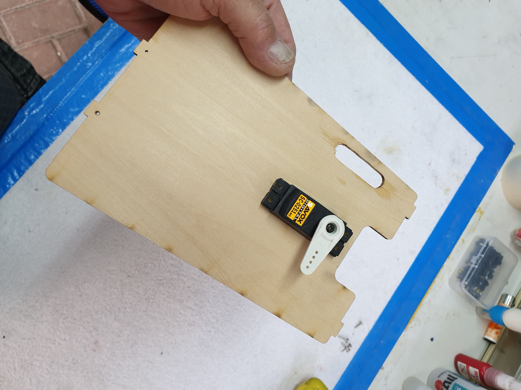
Front equipment shelf and the steering servo in it's new location. To make space for the batteries I used a carbon tube for front gear steering rather than the original pull/push cables system.
This configuration will later clear the space needed for service/removal of batteries trough the front gear hatch for external charging.
Two parts equipment shelf and the steering servo in it's original location.
The steering servo was placed beneath the front equipment shelf.
Front equipment shelf and the steering servo in it's new location. To make space for the batteries I used a carbon tube for front gear steering rather than the original pull/push cables system.
This configuration will later clear the space needed for service/removal of batteries trough the front gear hatch for external charging.
 03-19-2020, 03:01 AM
#38
Thread Starter
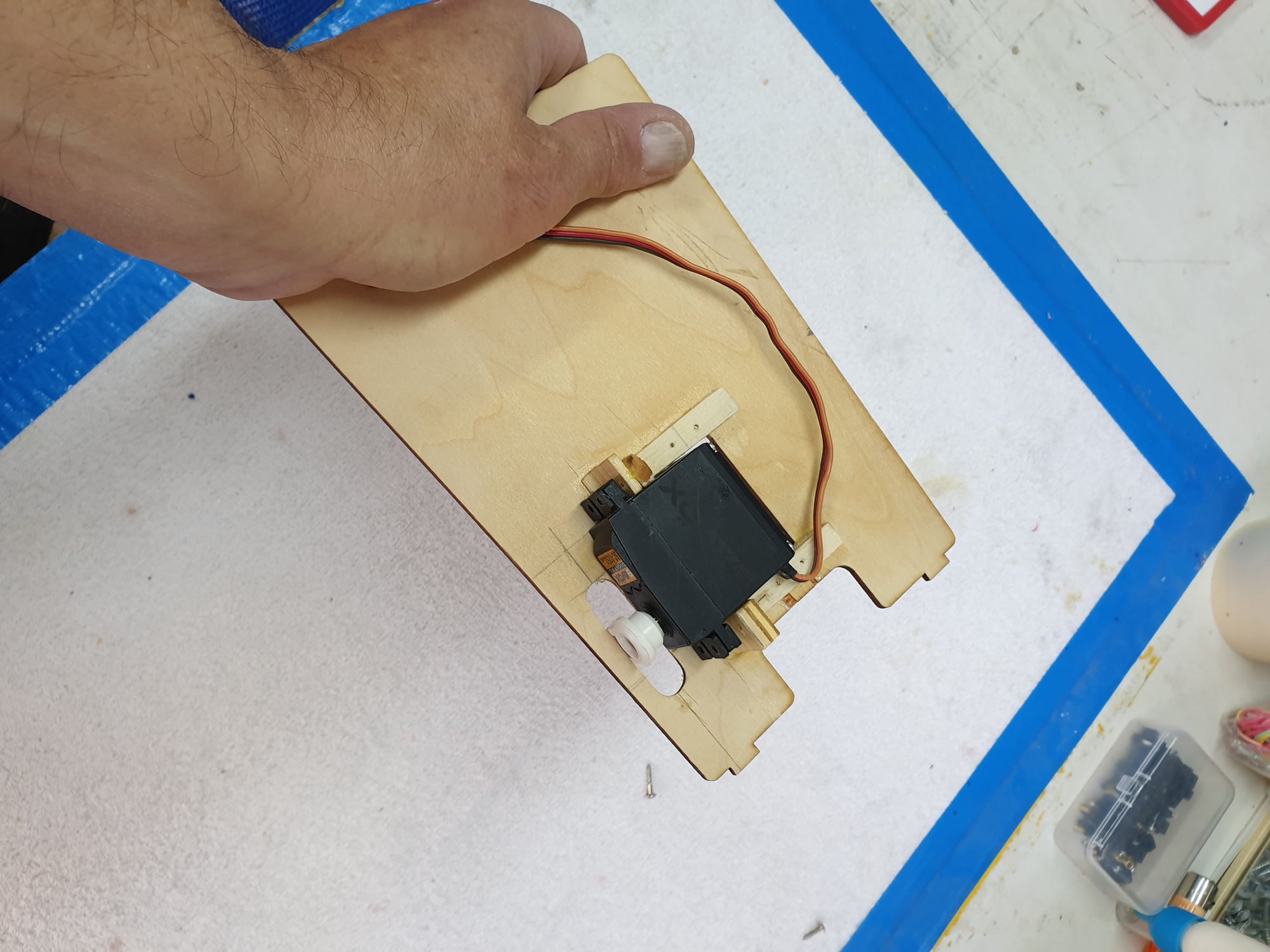
Yes, I used a 6 mm carbon tube with treads in both sides. One for the servo arm and the other to the steering crank. The steering crank side has a longer tread and bent twice to allow the needed travel.

The steering rod can be seen with the double direction change to enable the needed steering travel
03-19-2020, 03:59 AM
#39
Thread Starter
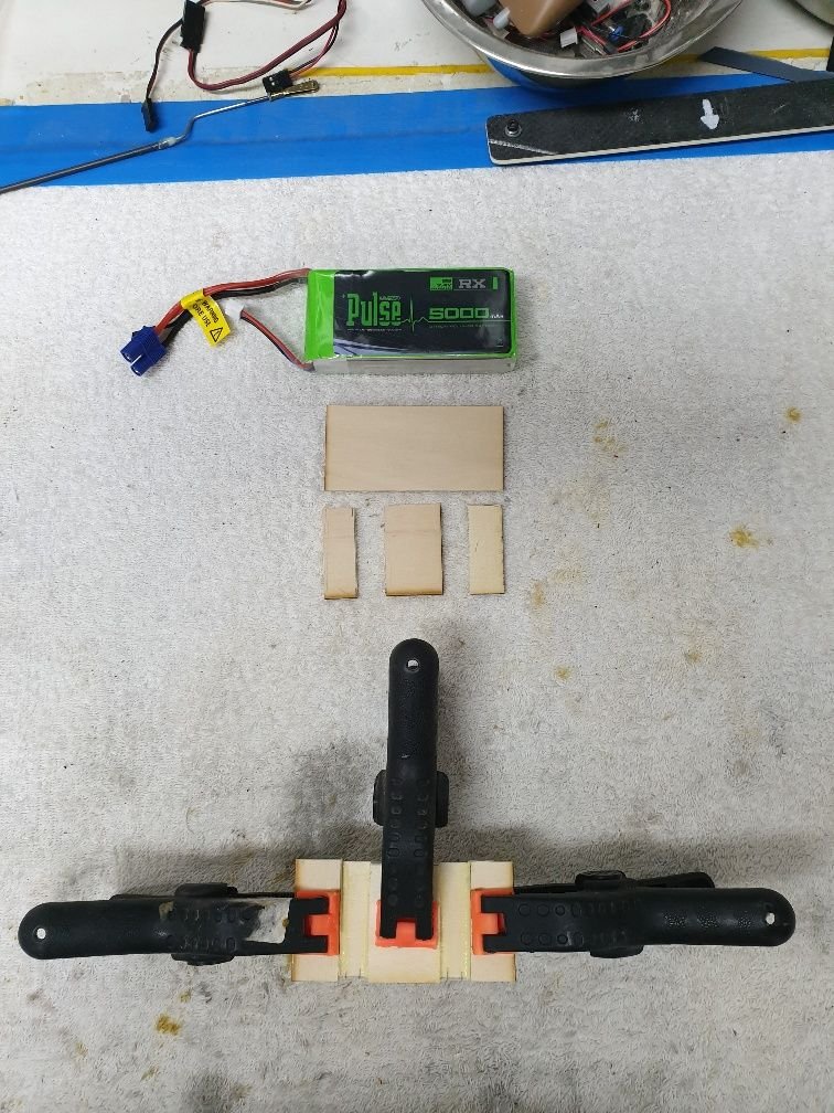
Batteries supports made from 5 mm plywood. One for each battery.
They are glued to the right side of the wheel compartment.
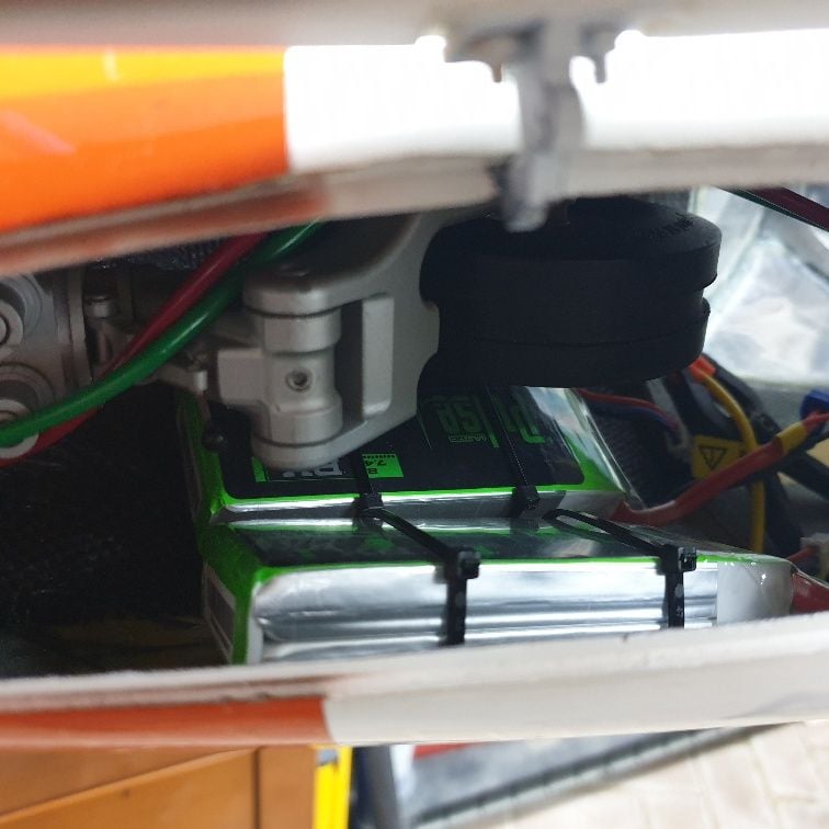
Batteries in location secured with valcro and tie wraps. They are removed for charge. This picture was taken during assembly. Now days the batteries are protected in the tie raps contact areas. The air lines are also routed as needed -NOT as in the picture.
03-28-2020, 05:19 AM
#40
Thread Starter
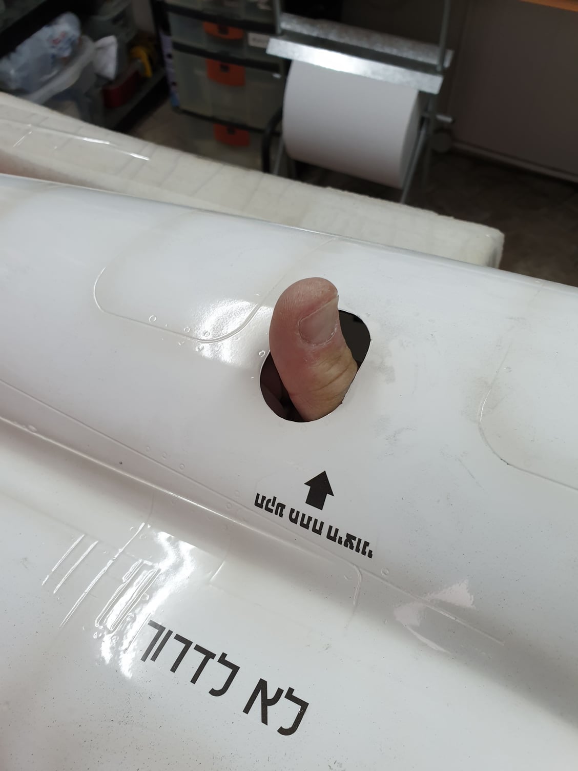
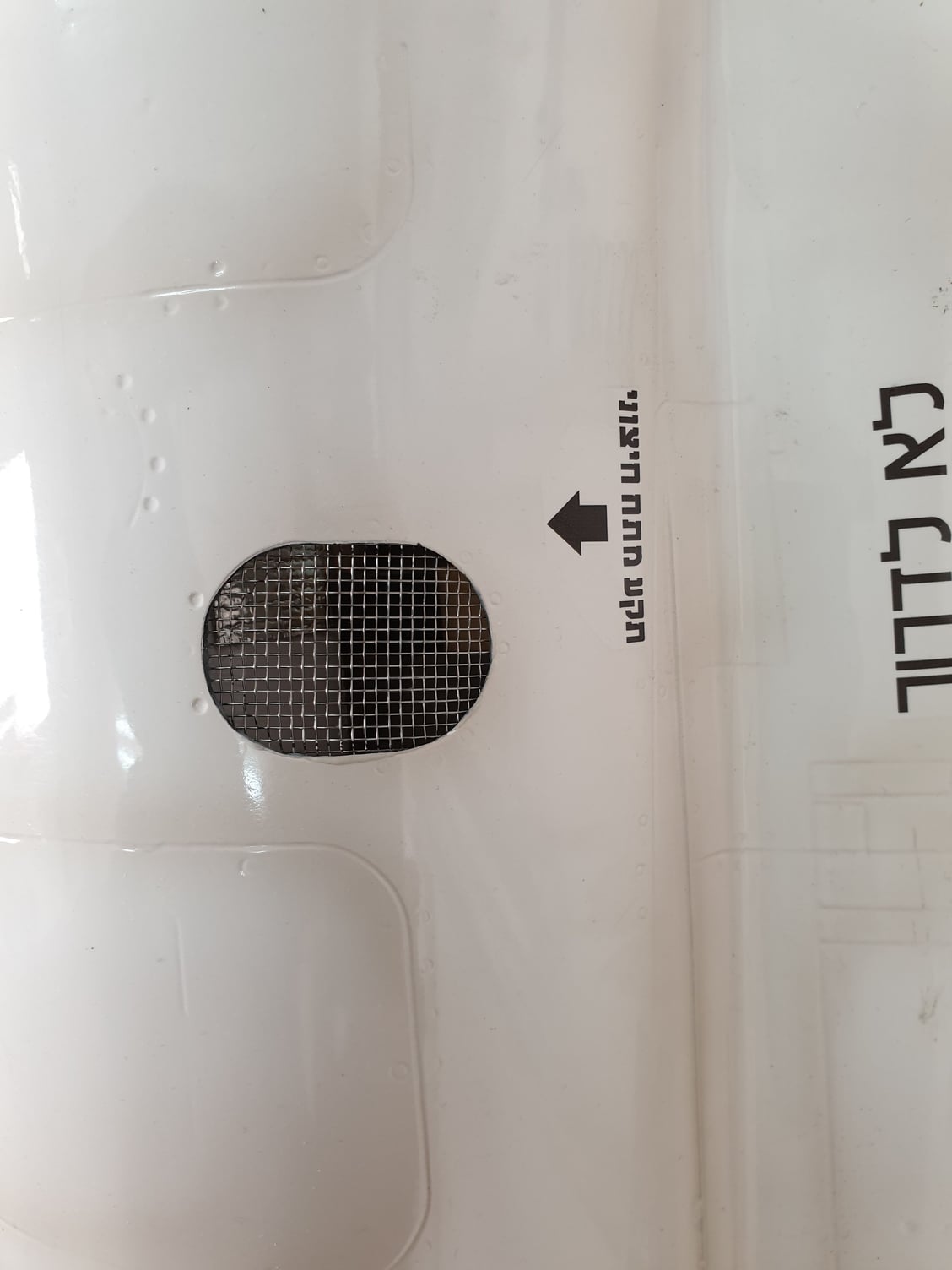
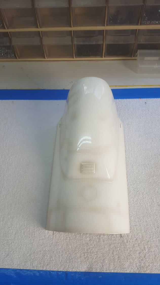
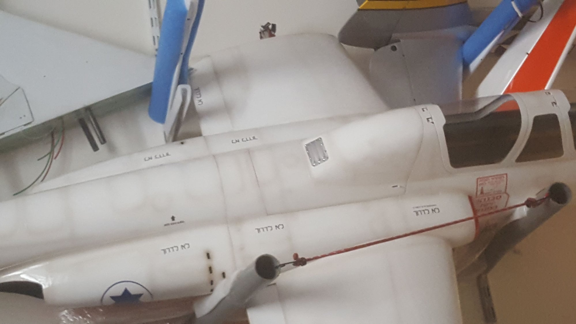
The heat generated from the tail pipe at the rear fuselage must be evacuated especially during taxi and hot days at the tarmac.
I used the full scale venting ports and scoops locations and used a medium kitchen pasta filter. I bought it especially not to harm any pasta diners in the future 😁

Full scale back of the Zukit. Note the different holes vents and scoops for air inlets/outle
I used the full scale venting ports and scoops locations and used a medium kitchen pasta filter. I bought it especially not to harm any pasta diners in the future 😁
Full scale back of the Zukit. Note the different holes vents and scoops for air inlets/outle
Last edited by avi sirota; 03-28-2020 at 05:39 AM.
03-28-2020, 05:29 AM
#41
Thread Starter
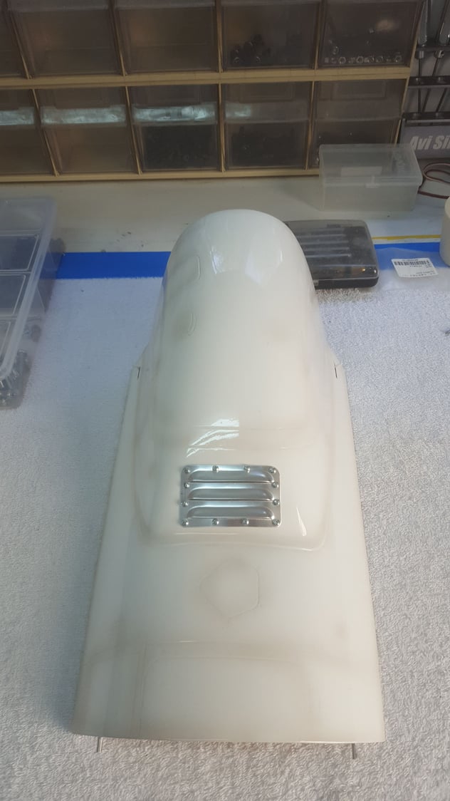
Later on during the build i added more vents and scoops. They all contribute to heat disposal and keeps the fuselage warm but not hot.
03-28-2020, 05:38 AM
#42
Thread Starter

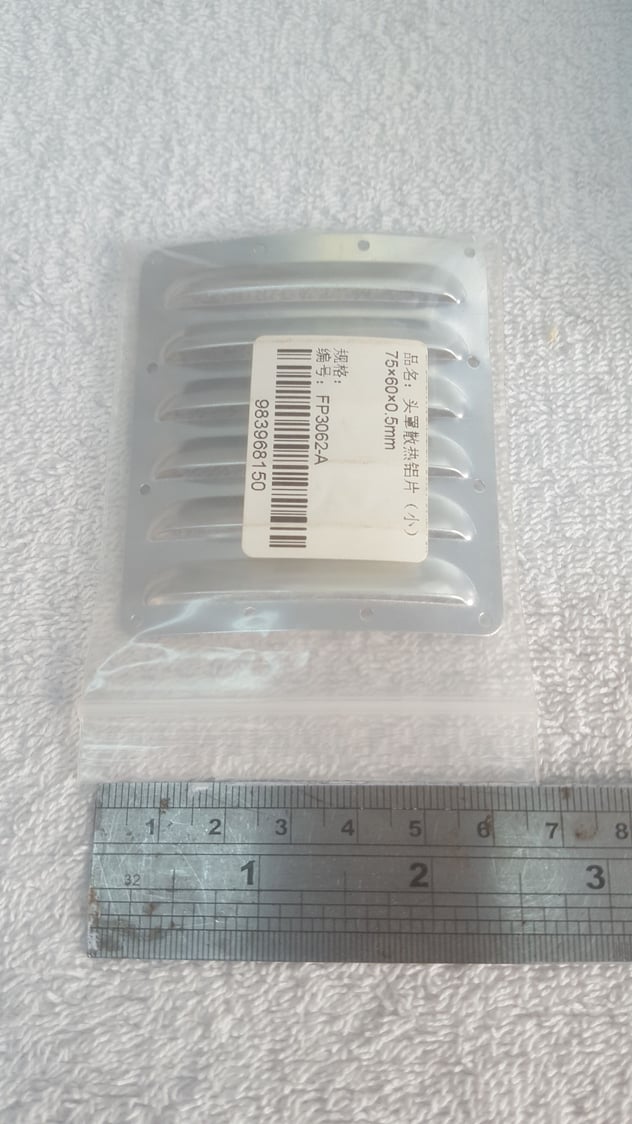
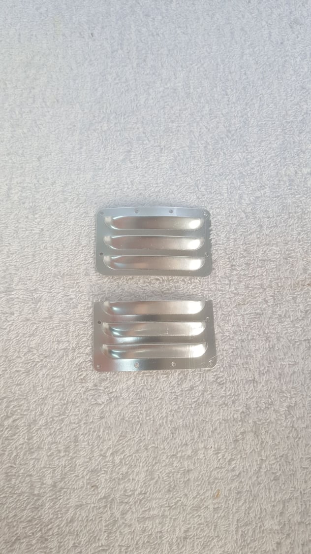
Marking the locations for air scoops. They must be positioned in such way not over the air tanks inside the rear fuselage. This was taken under consideration in positioning the air tanks and lines.
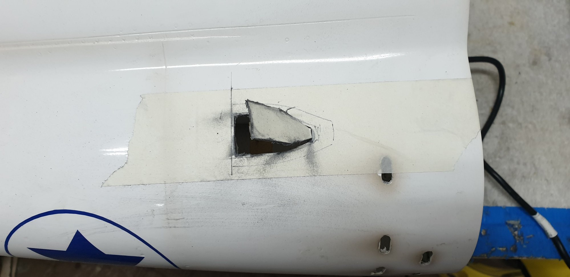
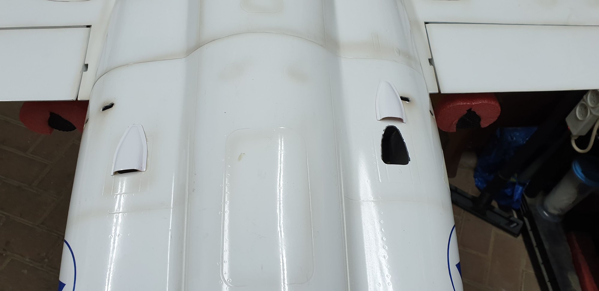
Scoops are supplied in the kit. They are well made and need to be slightly trimmed for good air passage before glue them in place.
03-28-2020, 10:27 AM
#44
Thread Starter
03-28-2020, 11:01 AM
#45
Thread Starter
Next challenging subject: the cockpits. There are 2 of them. One front and one rear. Each one is a "mini project". They are beautiful, detailed and can be "operational" if they are to be used as weight for balance.
At the beginning I thought Ill test fly the plane without the cockpits to make sure all systems are working properly and no fuel or air leaks.
Designing all systems layout and C.G I found it would be better to actualy use the almost 700 grams of cockpit weight instead of just balasts.
Doing all this at this point of the building sure delayed the total progress and extended the test flight planed time but for me it was a good thing. I learned more about the plane and did some modifications that might be difficult to implement later.
I wanted to have an easy access to all systems at the field if necessary. You have to bear in mind the cockpits are much weider than the opening at the canopies bottom meaning the cockpits must be inserted in a form of twist and turn routine...fun...
Last edited by avi sirota; 03-28-2020 at 11:05 AM.
03-28-2020, 11:17 AM
#46
Thread Starter
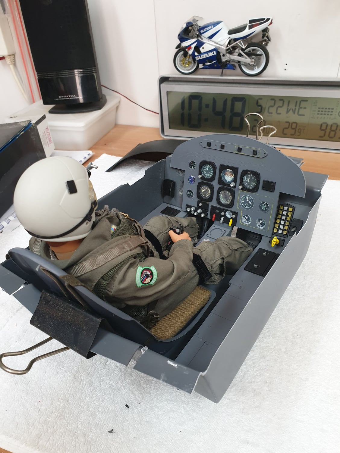
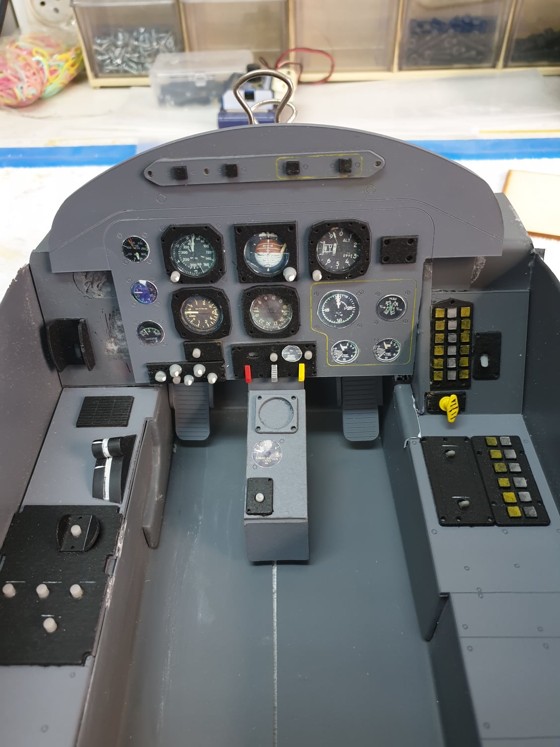
Here is the front cockpit I assembeled to get the general idea of the size and how the hell Ill squeeze it all in in one pice...No chance. It is slightly trrimed and adjusted NOT as it comes in the kit.
I finaly ended with each cockpit actually build from one floor, one seat, 2 side panels and one main instrument panel.
I wanted to be able to get it all out for service in minimum time effort or tools. At the field.
Last edited by avi sirota; 03-28-2020 at 11:22 AM.
03-29-2020, 01:28 AM
#47
Thread Starter
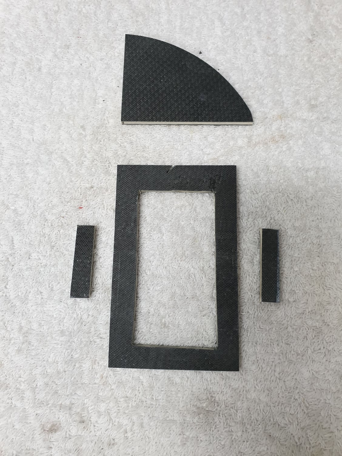
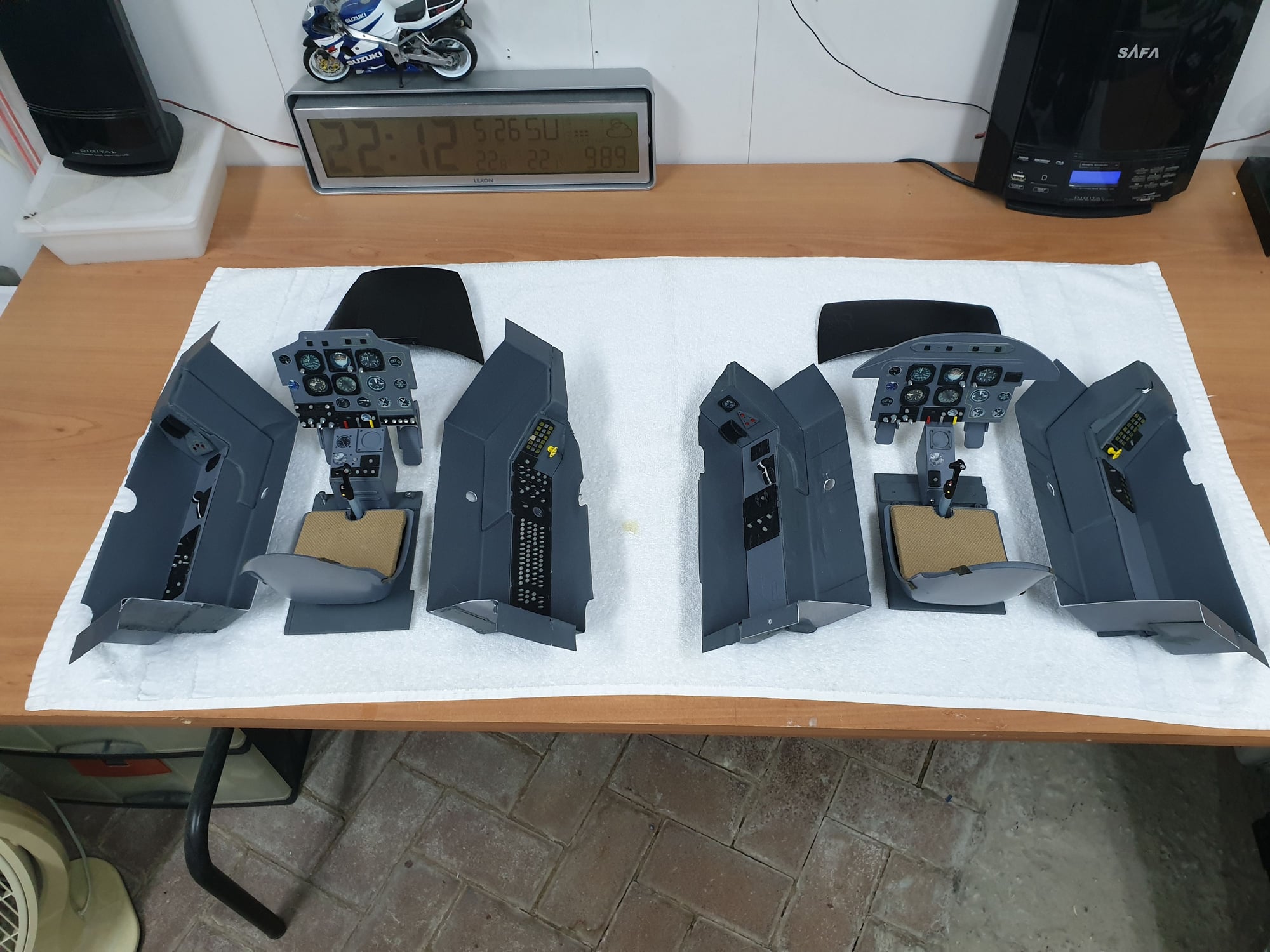
Some more pictures of the cockpits assembly. All was trimmed, cut, assembled and adjusted so it will keep the structure and integrity of the cockpits AND allow them to be quickly removable for service or inspection.
I used leftovers of what was cut to "reassemble" the structure.
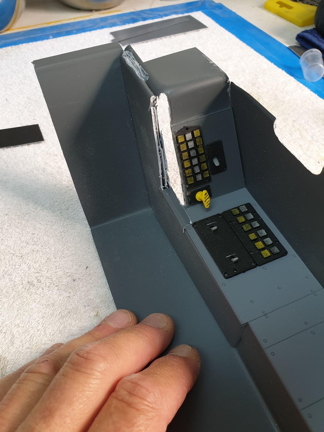
Right side panel was adjusted to make space for the front main panel. All side panels and floors got the same treatment.
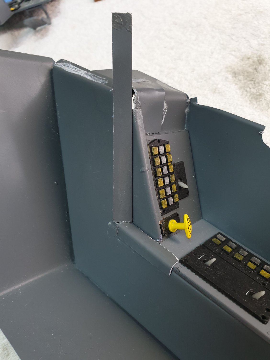
Leftovers to cover the trimmed material.
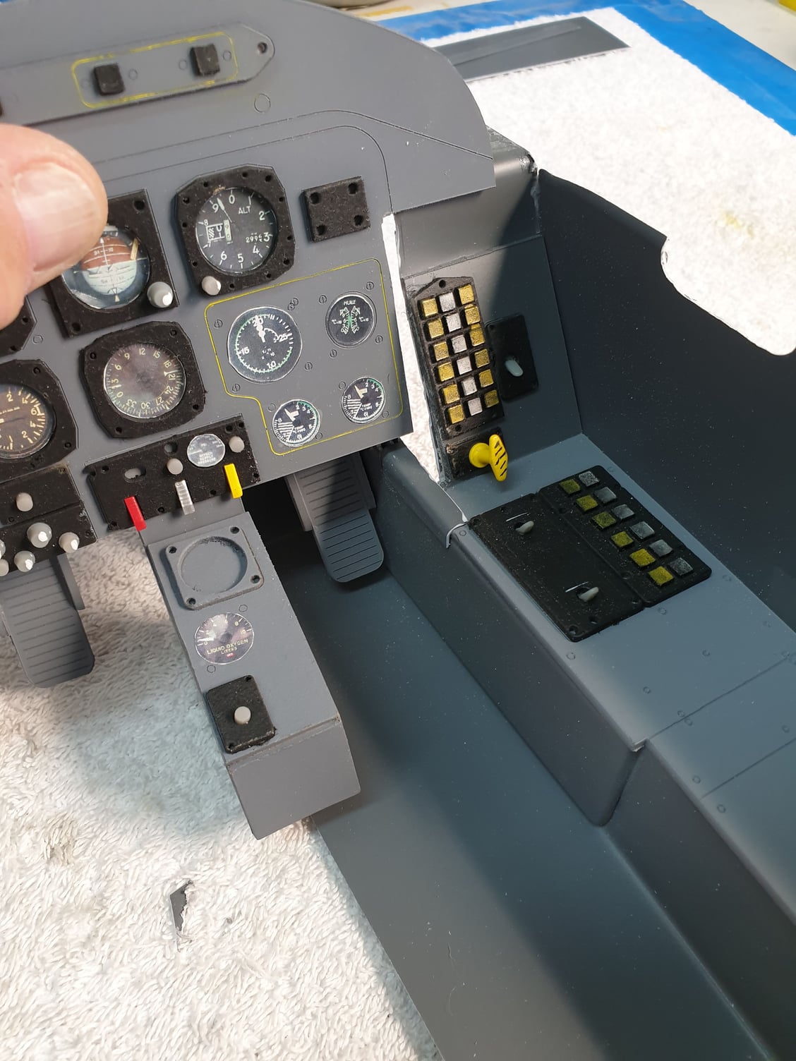
Main and side panels together. Note that the floor is cut in half to be able to insert the cockpit in sections.
I used leftovers of what was cut to "reassemble" the structure.
Right side panel was adjusted to make space for the front main panel. All side panels and floors got the same treatment.
Leftovers to cover the trimmed material.
Main and side panels together. Note that the floor is cut in half to be able to insert the cockpit in sections.
Last edited by avi sirota; 03-29-2020 at 10:56 PM.
03-29-2020, 02:28 AM
#48
Thread Starter
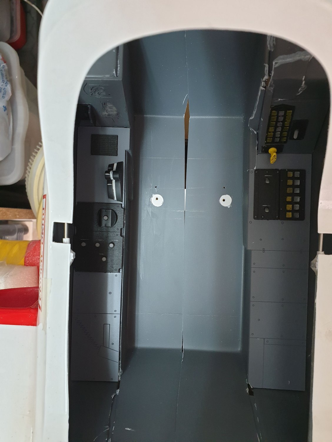
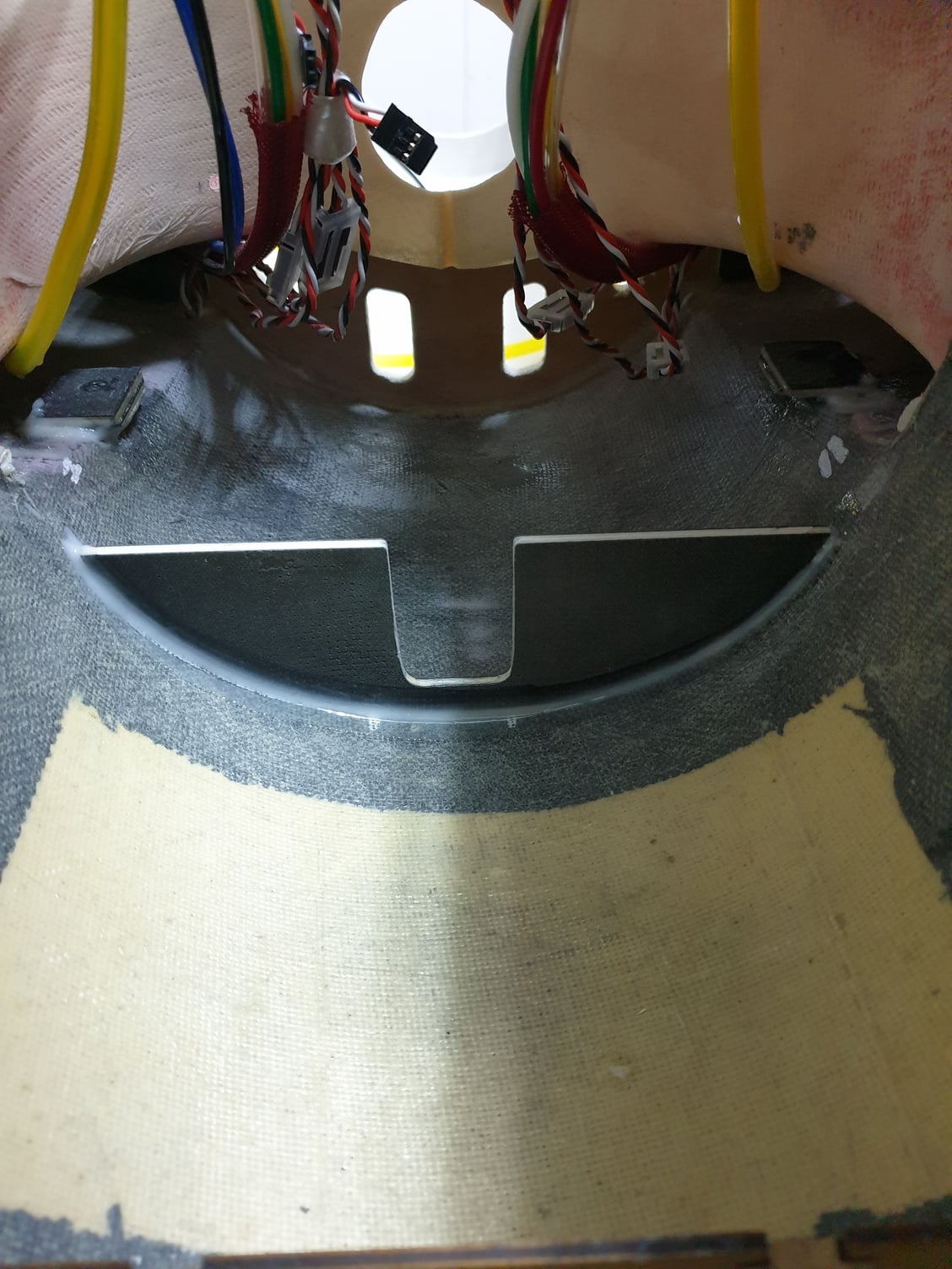
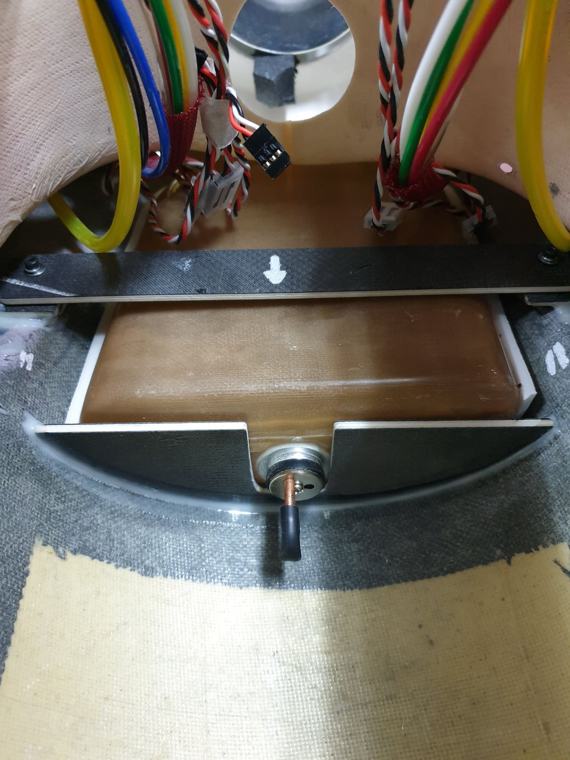
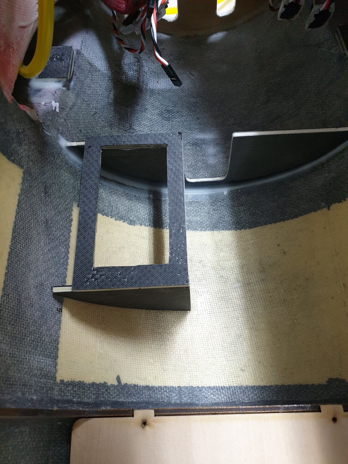
Two halfs sides together in the fuselage. Each cockpit structure is seating on crossmembers and secured with bolts. More pictures will follow.
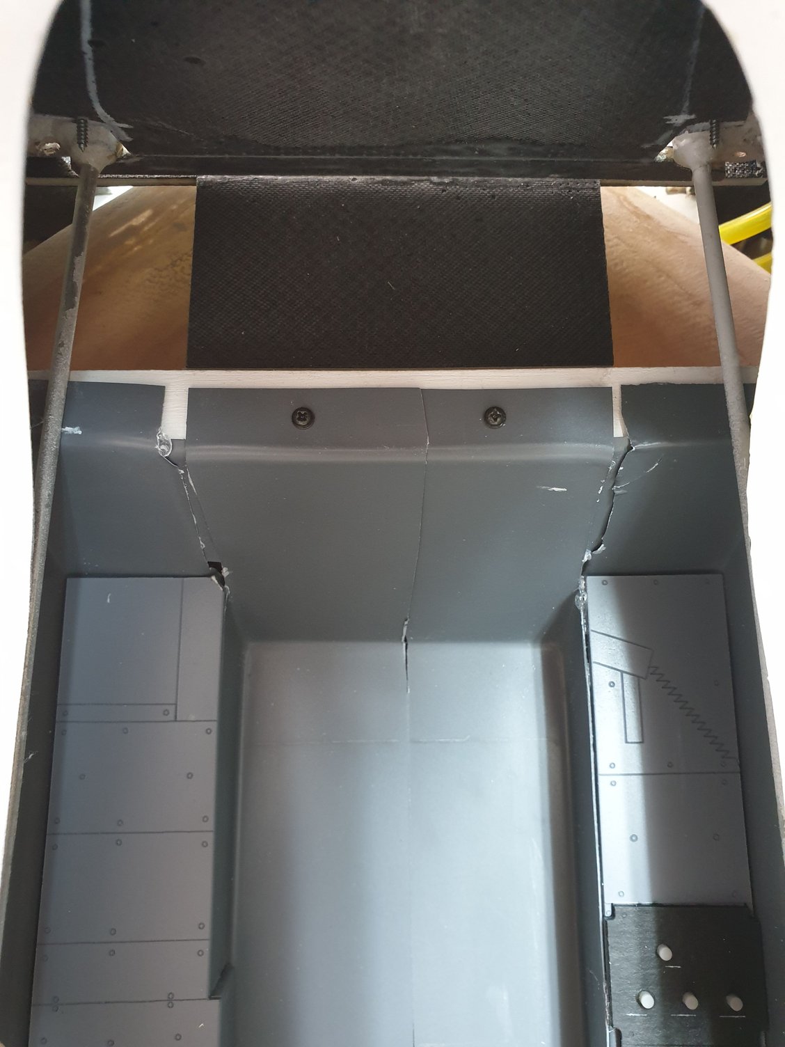
This is the aft part of the rear cockpit mounted on one of 3 crossmembers. Secured with 2 small screws. The black horizontal part seen in this picture is the turbine ECU mount.
Last edited by avi sirota; 03-29-2020 at 10:54 PM.
03-29-2020, 03:08 AM
#49
Thread Starter
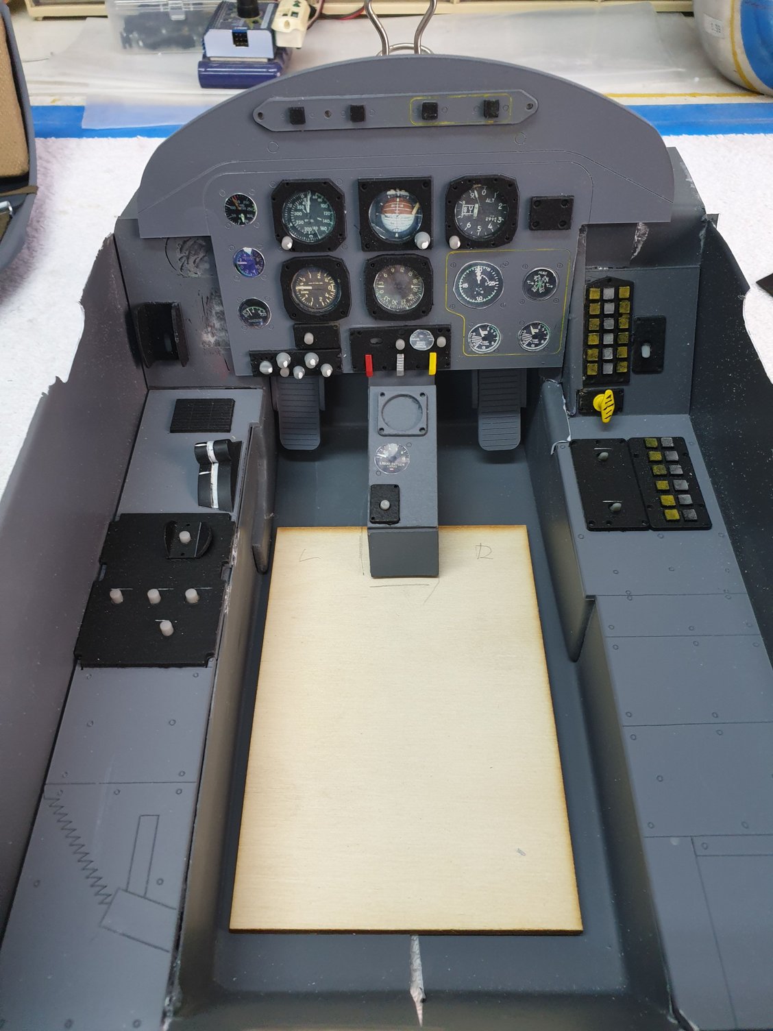
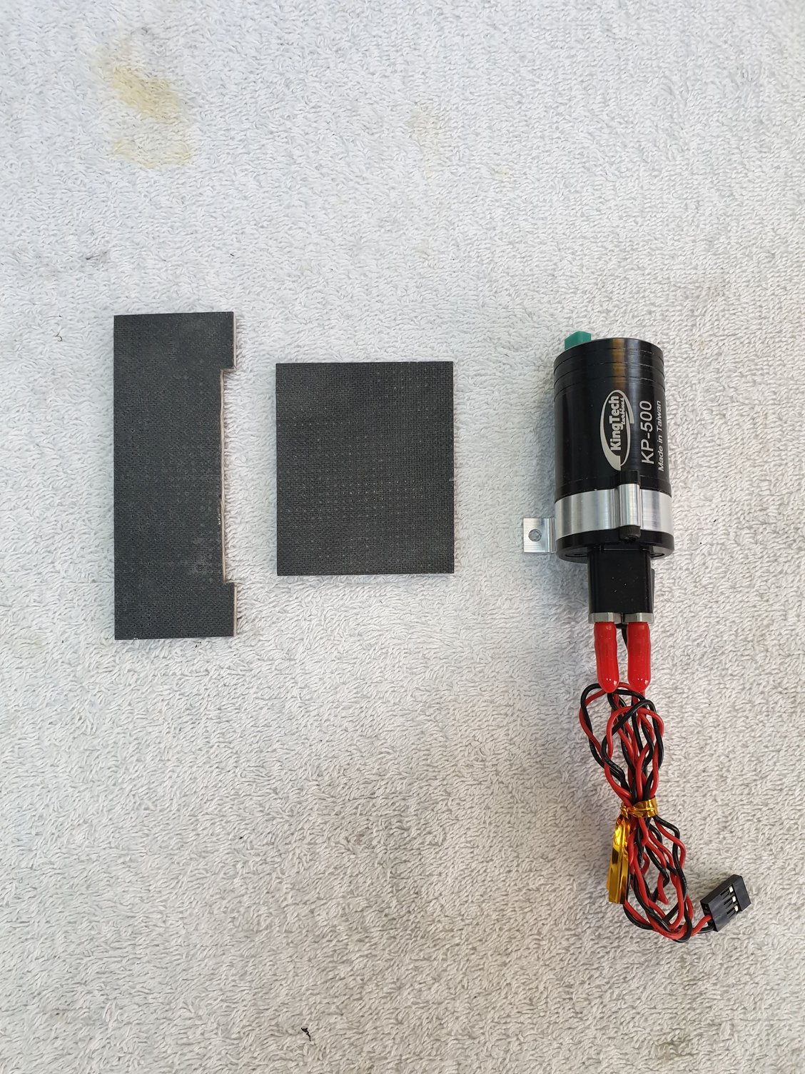
For each cockpit I made a floor from 2 mm plywood. This floor hold in place the seat and front main instrument panel and all is secure to the crossmember
More adjustments and trimming before touch up paint.
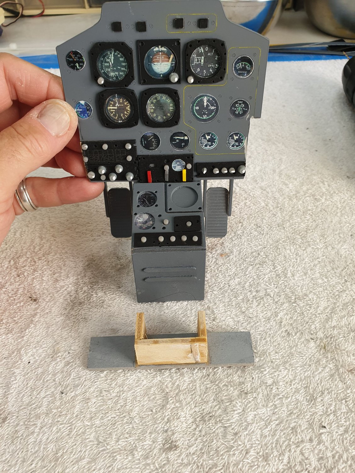
Front instrument panel is secured to a bracket. It is important for the "twist and turn" removal and installation.
I used the same method for front and rear cockpits.
Last edited by avi sirota; 03-29-2020 at 10:52 PM.
03-29-2020, 03:15 AM
#50
Thread Starter

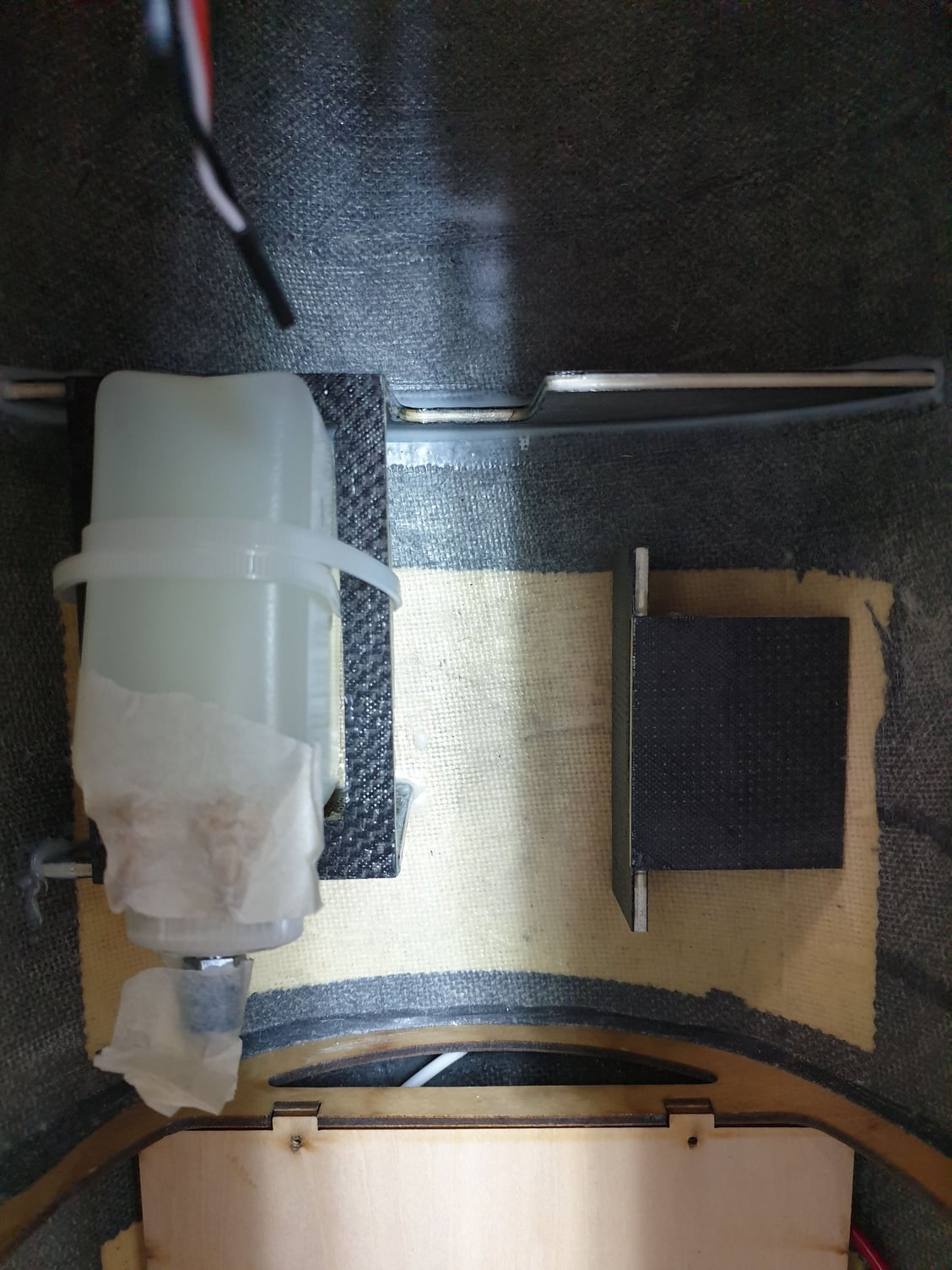
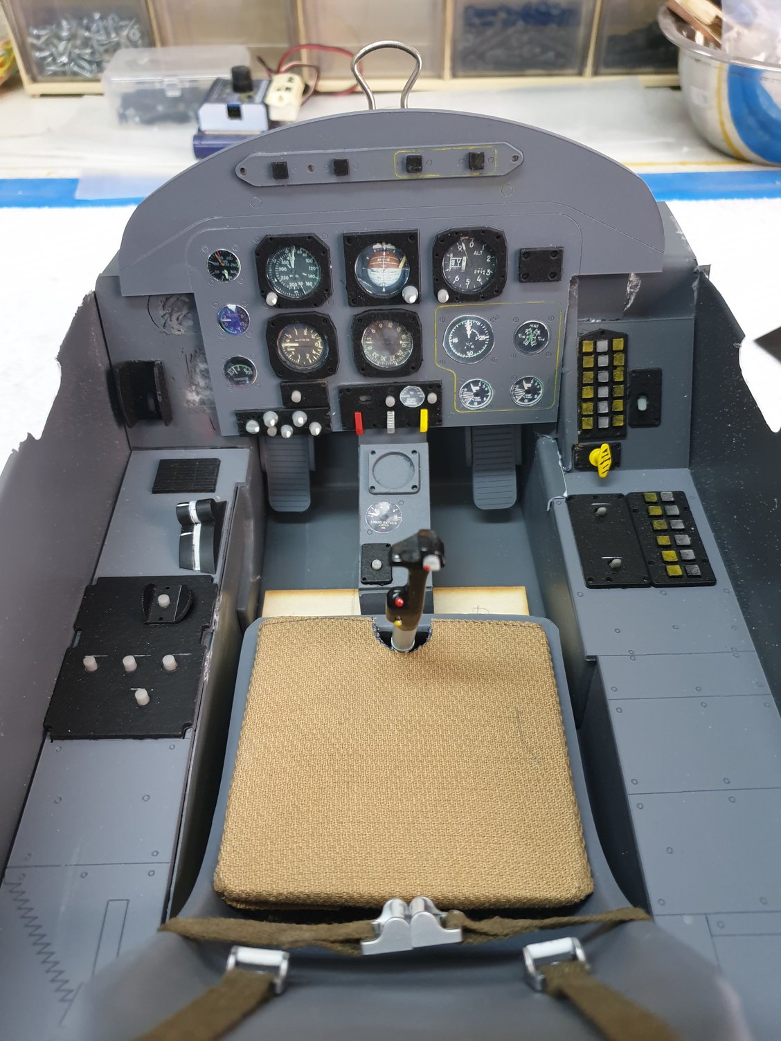
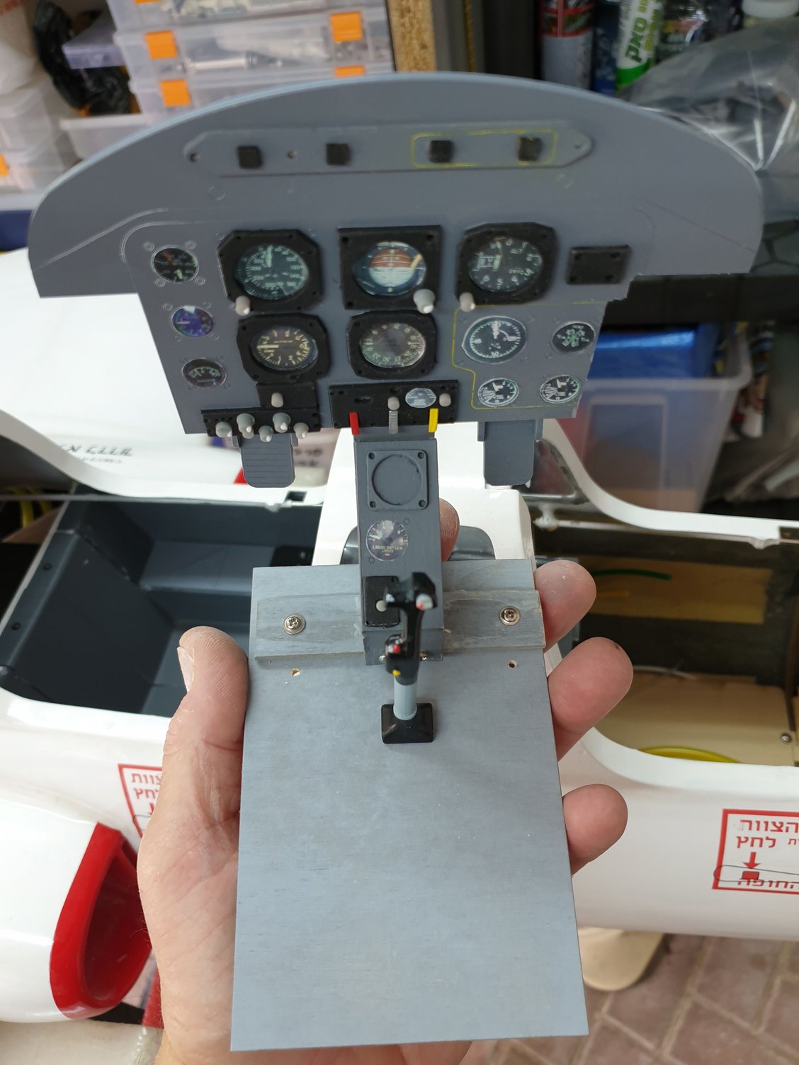
Measuring the rear cockpit floor to its location.
The cockpits are now ready to be installed. Each one has its dashboard panel trimmed to size as well. All in all this part was fun.
Next to follow is the "basement" bellow the cockpits floors...
Last edited by avi sirota; 03-29-2020 at 10:58 PM.