


F-16XL ARF by Global Knight Models from Global Jet Club

 06-22-2021, 05:39 PM
#277

Thread Starter
My Feedback: (20)
Repairs started on vertical fin damage
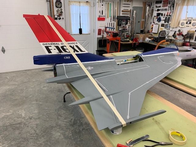
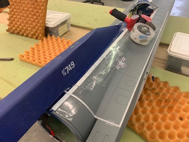
I finally got some shop time today and started repairs of the vertical fin damage. It is a fairly simple repair. I sanded the inside edges of the airex cracks with a double sided Perma Grit file to allow the parts to fit back together and removed damaged parts of both formers.
I used a long piece of masking tape to hold the vertical fin in position. The highly technical and complex TLAR method was used to get the precise angle for the vertical fin. Once the angle was set thin and medium CA glue was wicked in the cracked airex and the repair was tacked into place.
This shows the parts of the formers that were removed for the repairs. The next step is to epoxy the cracks from the inside and then lay in CF cloth to provide skin strength and a base for the replacement formers.
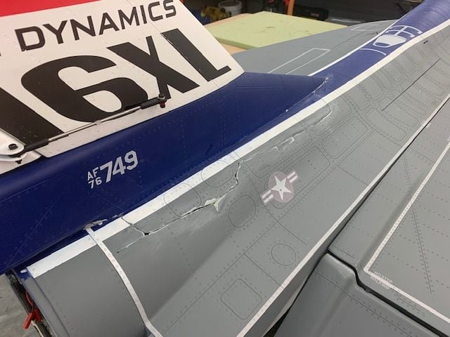
I found the fuse skin just behind the stars and bars insignia had a lot of flexing as the vertical fin was pushed side to side. This is where I will lay in CF cloth on the inside and extend the forward former down to the wing root. Some body work and paint is all that is needed on the outside. To be continued...
I finally got some shop time today and started repairs of the vertical fin damage. It is a fairly simple repair. I sanded the inside edges of the airex cracks with a double sided Perma Grit file to allow the parts to fit back together and removed damaged parts of both formers.
I used a long piece of masking tape to hold the vertical fin in position. The highly technical and complex TLAR method was used to get the precise angle for the vertical fin. Once the angle was set thin and medium CA glue was wicked in the cracked airex and the repair was tacked into place.
This shows the parts of the formers that were removed for the repairs. The next step is to epoxy the cracks from the inside and then lay in CF cloth to provide skin strength and a base for the replacement formers.
I found the fuse skin just behind the stars and bars insignia had a lot of flexing as the vertical fin was pushed side to side. This is where I will lay in CF cloth on the inside and extend the forward former down to the wing root. Some body work and paint is all that is needed on the outside. To be continued...
Last edited by Viper1GJ; 06-22-2021 at 05:46 PM.
06-23-2021, 03:38 AM
#278
Hi Gary,
The repair tenacity you display never surprises me!
Im convinced that anything that gets damaged within the fleet is back of its feet and flight line ready within weeks!
Always an education reviewing your threads.
Talk soon,
Frank
The repair tenacity you display never surprises me!
Im convinced that anything that gets damaged within the fleet is back of its feet and flight line ready within weeks!
Always an education reviewing your threads.
Talk soon,
Frank
The following users liked this post:
Viper1GJ (06-23-2021)
06-24-2021, 04:51 PM
#279
Thread Starter
My Feedback: (20)
Crack repair continued...
I planned to back fill the inside of the crack with epoxy. First I applied clear packing tape to the outside of the crack to form a base for the epoxy fill.
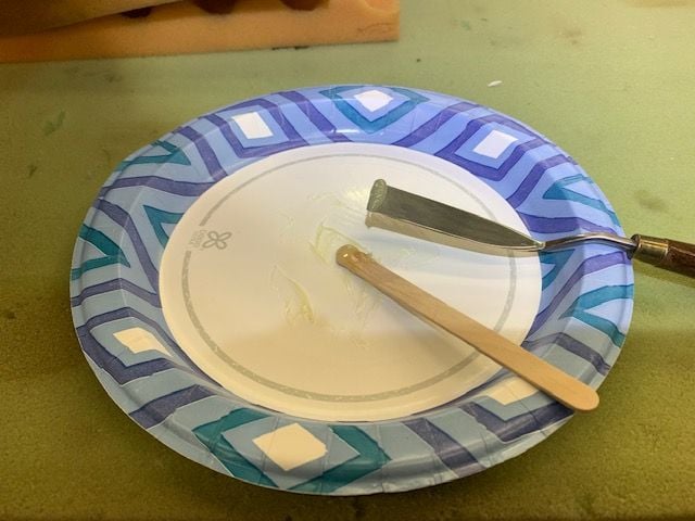
Next I scuff sanded all the around the cracked area and then mixed a batch of thick Six10 epoxy on paper plate
The Six10 epoxy is applied to the crack with a popsicle stick. Hard to see in photo.
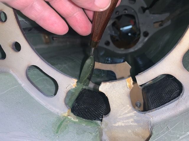
A narrow flat blade tool used to trowel the epoxy into the crack and remove excess
End result is a filled crack ready for the carbon fiber layup on the inside. I used a flashlight to highlight the crack when working.
I planned to back fill the inside of the crack with epoxy. First I applied clear packing tape to the outside of the crack to form a base for the epoxy fill.
Next I scuff sanded all the around the cracked area and then mixed a batch of thick Six10 epoxy on paper plate
The Six10 epoxy is applied to the crack with a popsicle stick. Hard to see in photo.
A narrow flat blade tool used to trowel the epoxy into the crack and remove excess
End result is a filled crack ready for the carbon fiber layup on the inside. I used a flashlight to highlight the crack when working.
 06-26-2021, 04:54 PM
#282
Thread Starter
My Feedback: (20)
Structural repairs on tail complete.
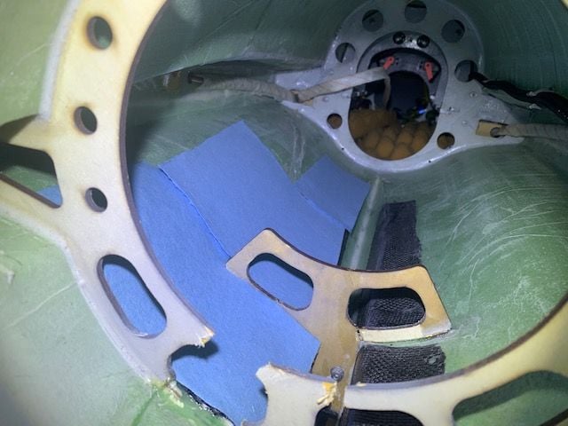
Blue shop towels used to make patterns for CF cloth. I elected to use 3 parts to make it easier to lay in the fuse since it has to be placed from the rear hole.
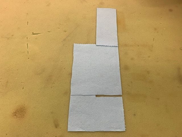
Patterns complete
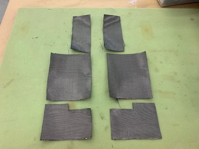
Carbon cloth cut and ready to wet out.
CF cloth laid in with epoxy.
Broken rear former pieced back together and a doubler cut to tie cracked parts together.
Former doubler epoxied in place
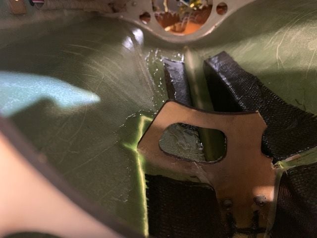
Large fillet of thick Six10 epoxy laid in on both sides of the formers to tie former loads to the new CF lamination but it's hard to see in the photo. I was going to extend the front former out to the wing strakes but I found that the overlapped double layer of CF cloth extends to the wing strake right at the former station. This made the fuse skin really stiff outside of the front former so I elected leave it as is.
Lower part of aft former repaired. A popsicle stick was just the right thickness to fit into the missing part.
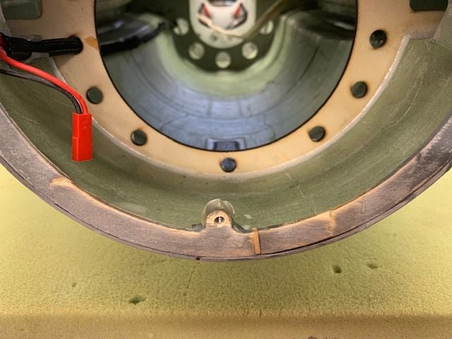
Small cracks in AB nozzle repaired and AB LED ring reinstalled.
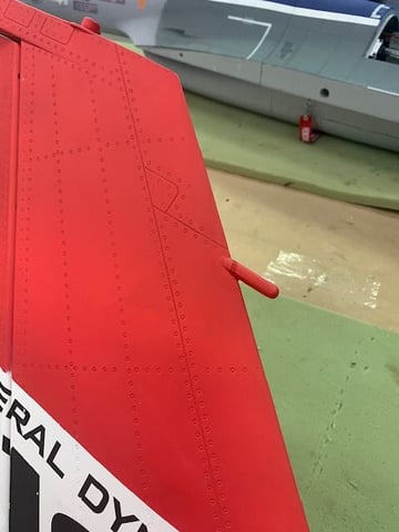
Air refueling light glued back on fin leading edge and red touch up craft paint applied.
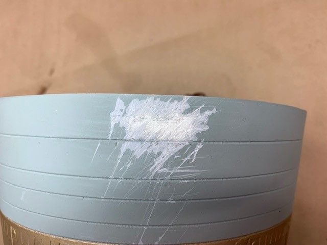
The bottom of the AB nozzle had some scratches so I decided to try my Home Depot touch up paint to see how close it matched.
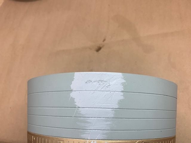
Not! I realized the nozzle grey is not the same as the dark or light grey on the jet. I had just assumed it was the same light grey.
The touch up paint actually matches the light grey on the bottom as it should.
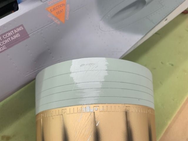
So the nozzle with get painted with the light grey primer color as I used on the nose repaint. Easy fix.
Blue shop towels used to make patterns for CF cloth. I elected to use 3 parts to make it easier to lay in the fuse since it has to be placed from the rear hole.
Patterns complete
Carbon cloth cut and ready to wet out.
CF cloth laid in with epoxy.
Broken rear former pieced back together and a doubler cut to tie cracked parts together.
Former doubler epoxied in place
Large fillet of thick Six10 epoxy laid in on both sides of the formers to tie former loads to the new CF lamination but it's hard to see in the photo. I was going to extend the front former out to the wing strakes but I found that the overlapped double layer of CF cloth extends to the wing strake right at the former station. This made the fuse skin really stiff outside of the front former so I elected leave it as is.
Lower part of aft former repaired. A popsicle stick was just the right thickness to fit into the missing part.
Small cracks in AB nozzle repaired and AB LED ring reinstalled.
Air refueling light glued back on fin leading edge and red touch up craft paint applied.
The bottom of the AB nozzle had some scratches so I decided to try my Home Depot touch up paint to see how close it matched.
Not! I realized the nozzle grey is not the same as the dark or light grey on the jet. I had just assumed it was the same light grey.
The touch up paint actually matches the light grey on the bottom as it should.
So the nozzle with get painted with the light grey primer color as I used on the nose repaint. Easy fix.
06-27-2021, 01:53 PM
#283
Thread Starter
My Feedback: (20)
Nose gear plate and nose gear door repairs
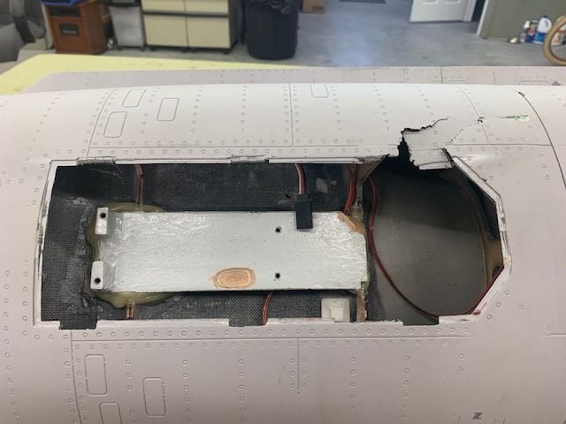
This is my field repair from FIF. The nose gear tore the airex skin when it came out and got dragged into the main gear well. The nose door hinges were loose so I removed the door before flying with the fixed nose gear.
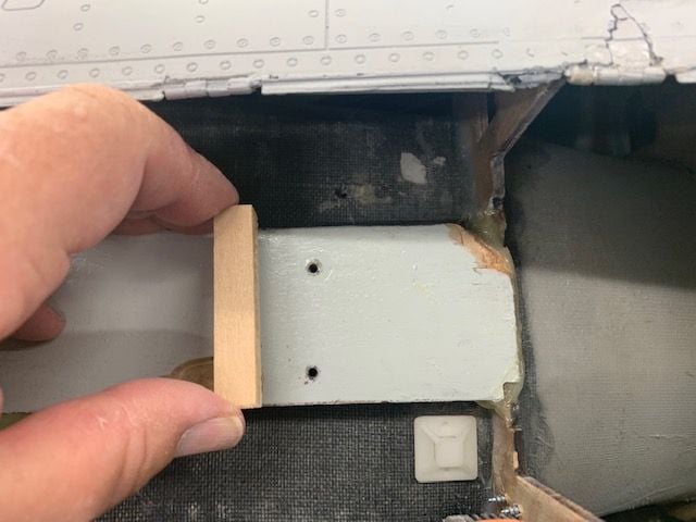
Airex tears in the upper right repaired and ready for filler and sanding. I took Josh's suggestion to add an additional brace under the gear plate to keep it from flexing and add some more gluing surface to the carbon fiber base. I made a poplar block that will fit under the plate just forward of the blind nut holes.

Popsicle stick tool I made to apply the epoxy under the plate and to the CF base
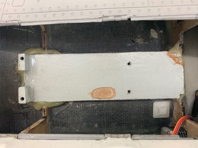
Gear plate repairs complete
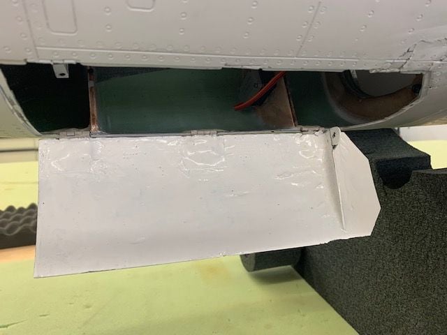
Nose gear door reinstalled. This was the hardest part of all the repairs including the vertical fin. Getting this thing back in and working with out binding even with the hinges half installed was a pain. I hate gear doors!
This is my field repair from FIF. The nose gear tore the airex skin when it came out and got dragged into the main gear well. The nose door hinges were loose so I removed the door before flying with the fixed nose gear.
Airex tears in the upper right repaired and ready for filler and sanding. I took Josh's suggestion to add an additional brace under the gear plate to keep it from flexing and add some more gluing surface to the carbon fiber base. I made a poplar block that will fit under the plate just forward of the blind nut holes.
Popsicle stick tool I made to apply the epoxy under the plate and to the CF base
Gear plate repairs complete
Nose gear door reinstalled. This was the hardest part of all the repairs including the vertical fin. Getting this thing back in and working with out binding even with the hinges half installed was a pain. I hate gear doors!
06-28-2021, 04:36 PM
#284
Thread Starter
My Feedback: (20)
Nose cone scuffs repaired
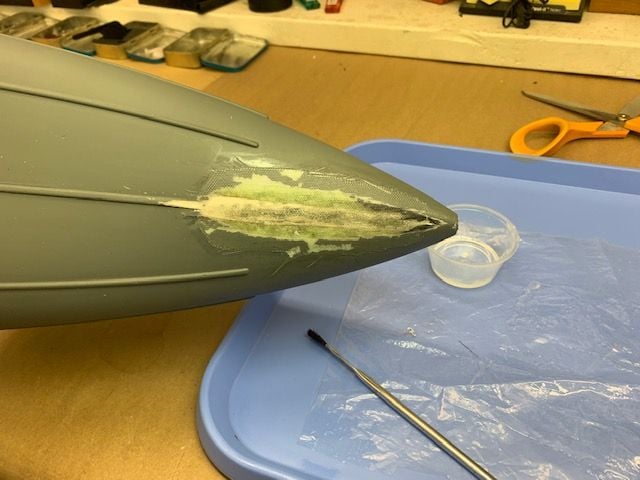
6oz fiberglass laminated on inside nad outside of nose cone where it was scuffed through when the nose gear mount fell out. All the structural damage is now fixed except for body work and painting.
6oz fiberglass laminated on inside nad outside of nose cone where it was scuffed through when the nose gear mount fell out. All the structural damage is now fixed except for body work and painting.
07-01-2021, 05:35 PM
#285
Thread Starter
My Feedback: (20)
New pitot tube and brake controller
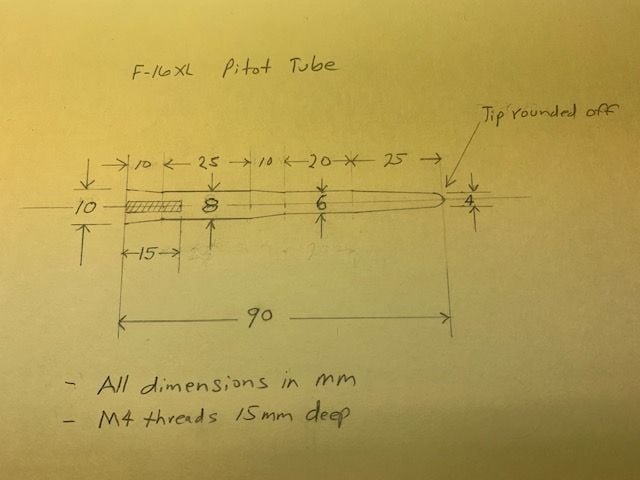
I sketched up a drawing for a new pitot tube to replace the one that got ground flat in the take off wreck at FIF. My friend Tom has a lathe and says he can make one from aluminum. I reduced the size of the base from 12 to 10mm and hopefully it will fit the nose cone better than the first one.
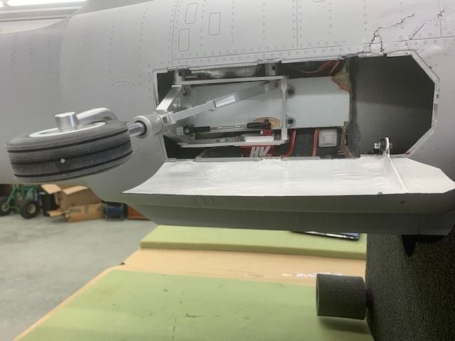
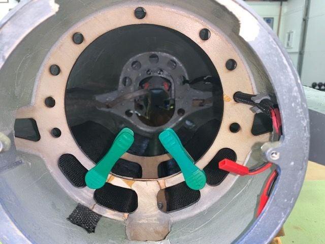
New nose gear installed on the repaired gear plate. Hopefully this one will stay in.
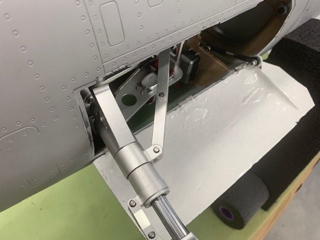
The diagonal strut brace on this nose gear is perfectly straight and locked. My first one was not and folded on the first flight.
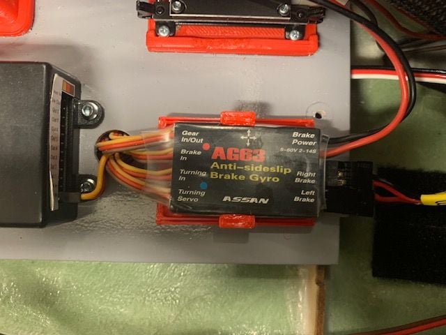
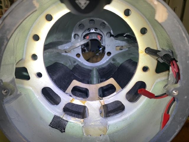
Here is the Assan AG63 brake controller that Mike, Josh, and Robert are using with success. They recommended that I use 3S voltage on the brakes since mine did not work well on 2S before. The gear motors need 2S voltage and I was unable to get two different voltages from the LGC-15 controller. The AG63 gets 3S braking voltage directly from one of the flight batteries. Initial roll testing in the shop seems to indicate this one works well on steering. It tracks perfectly straight even though I know my nose wheel was not exactly straight when I started. Not too bad!
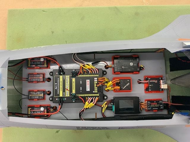
I finally got the RC equipment tray and all the new wiring stuffed back in. The open spot in the upper right is where the light controller will go. I could never get the JP controller and lights to work so I ordered a foamie controller from Motion RC and will replace the gear lights and controller when they arrive.
I sketched up a drawing for a new pitot tube to replace the one that got ground flat in the take off wreck at FIF. My friend Tom has a lathe and says he can make one from aluminum. I reduced the size of the base from 12 to 10mm and hopefully it will fit the nose cone better than the first one.
New nose gear installed on the repaired gear plate. Hopefully this one will stay in.
The diagonal strut brace on this nose gear is perfectly straight and locked. My first one was not and folded on the first flight.
Here is the Assan AG63 brake controller that Mike, Josh, and Robert are using with success. They recommended that I use 3S voltage on the brakes since mine did not work well on 2S before. The gear motors need 2S voltage and I was unable to get two different voltages from the LGC-15 controller. The AG63 gets 3S braking voltage directly from one of the flight batteries. Initial roll testing in the shop seems to indicate this one works well on steering. It tracks perfectly straight even though I know my nose wheel was not exactly straight when I started. Not too bad!
I finally got the RC equipment tray and all the new wiring stuffed back in. The open spot in the upper right is where the light controller will go. I could never get the JP controller and lights to work so I ordered a foamie controller from Motion RC and will replace the gear lights and controller when they arrive.
07-01-2021, 08:33 PM
#286
My Feedback: (2)
No complaints with the AG63, just needs to be setup correctly. Flight from today, I was trying out higher alpha today passes today. I also noticed that one of the elevators are not completely even at full deflection so need to adjust that, it's banking to the left and I am correcting it right aileron on landing. Not a big deal just minor adjustments.
The following users liked this post:
BadBill (07-02-2021)


The following users liked this post:
yeahbaby (07-02-2021)
07-02-2021, 04:05 PM
#289
Thread Starter
My Feedback: (20)
Priming nozzle cone
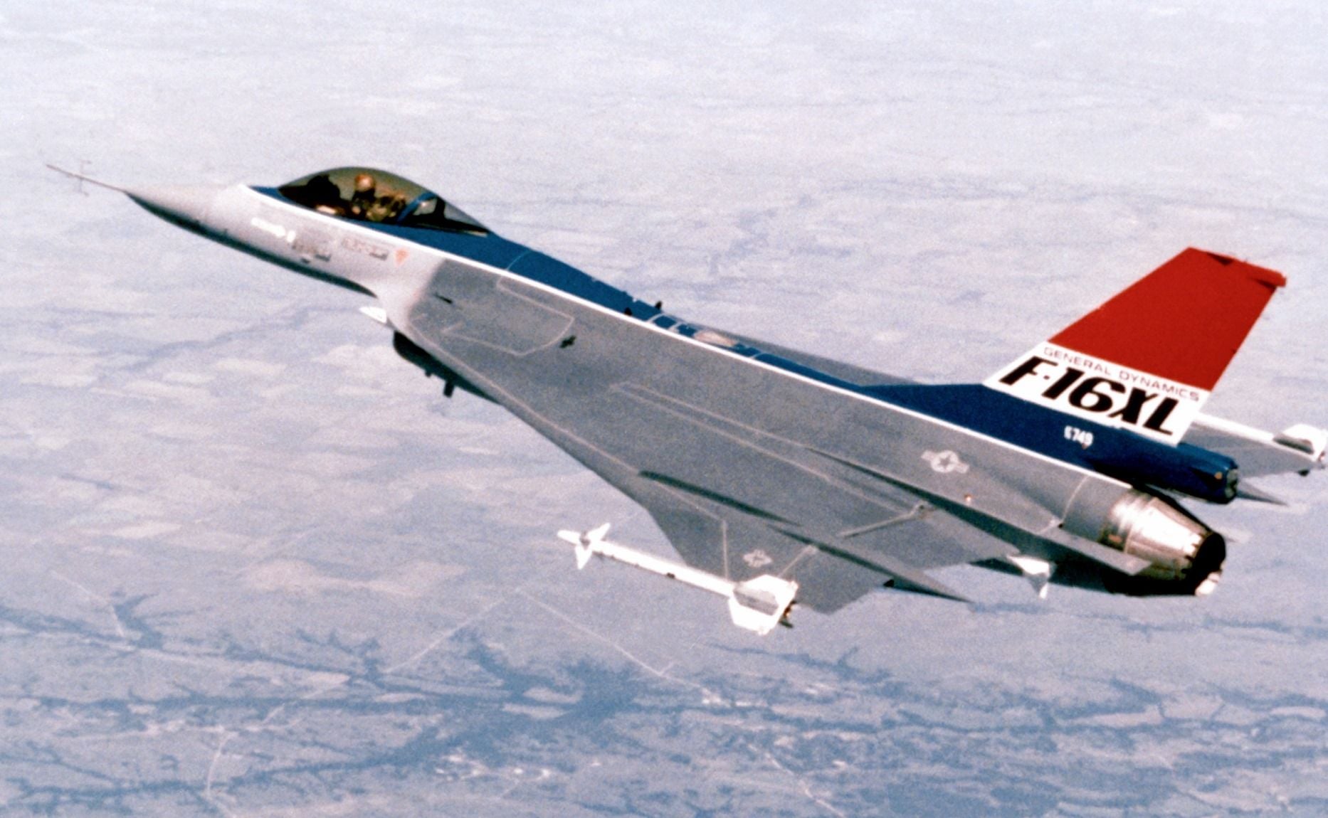
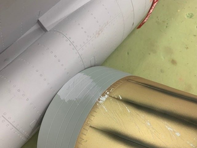
I was looking to repaint the front ring of the nozzle assembly to cover up the scratches and I couldn't figure out why it was painted an off color of grey. Then I found several internet photos and drawings where it looks to be a light grey. However, it really is the bare metal color of the aft part of the engine burner can just, forward of the nozzle, sticking out behind the dark grey fuse skin. You can easily see it here in the full scale photo. So I just decided to shoot some grey primer on it for now and I will try later to paint it to look like bare metal. I would recommend future production paint better reflect the actual parts of the full scale jet.
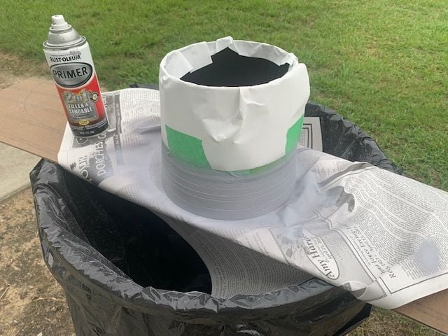
Nozzle turkey feathers masked off for primer spray
Primer dry and masking removed
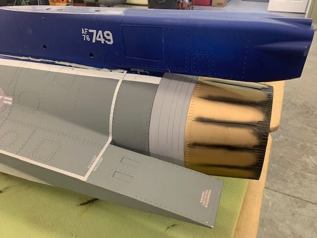
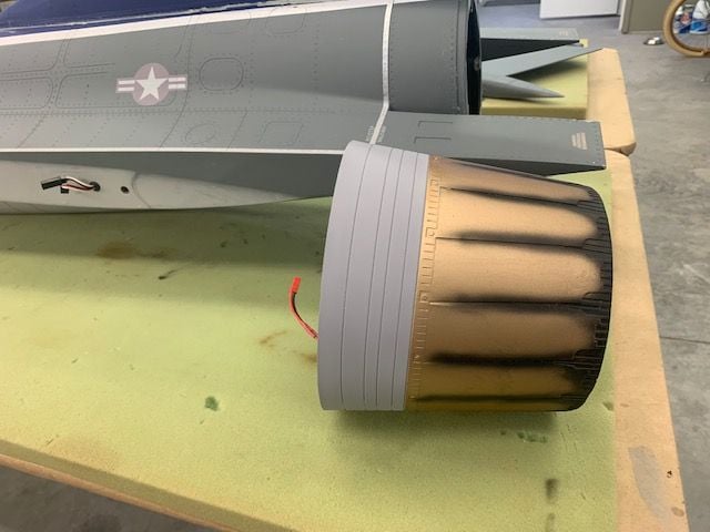
I think when I repaint the nozzle I will try to make the burner can a dark silver the turkey feathers less gold and a little more dark silver color to better reflect the Pratt Whitney F-100 turkey feathers.
I was looking to repaint the front ring of the nozzle assembly to cover up the scratches and I couldn't figure out why it was painted an off color of grey. Then I found several internet photos and drawings where it looks to be a light grey. However, it really is the bare metal color of the aft part of the engine burner can just, forward of the nozzle, sticking out behind the dark grey fuse skin. You can easily see it here in the full scale photo. So I just decided to shoot some grey primer on it for now and I will try later to paint it to look like bare metal. I would recommend future production paint better reflect the actual parts of the full scale jet.
Nozzle turkey feathers masked off for primer spray
Primer dry and masking removed
I think when I repaint the nozzle I will try to make the burner can a dark silver the turkey feathers less gold and a little more dark silver color to better reflect the Pratt Whitney F-100 turkey feathers.
07-02-2021, 04:10 PM
#290
Thread Starter
My Feedback: (20)
No complaints with the AG63, just needs to be setup correctly. Flight from today, I was trying out higher alpha today passes today. I also noticed that one of the elevators are not completely even at full deflection so need to adjust that, it's banking to the left and I am correcting it right aileron on landing. Not a big deal just minor adjustments.
I'm looking forward to trying my AG63. It seems to work well in the shop so far. Also I am running full span elevons where the inboard elevons and ailerons are all mixed for pitch and roll together similar to the full scale set up. Seems to work really well so far. I'll be out of town for the next week paying my "RC dues" so hopefully will get it flying again soon after that.
Gary
07-07-2021, 06:10 AM
#291
Someone posted on Facebook that there have been two vertical stab failures, I only know of Gary"s issue, any other? I am putting a little reinforcement in anyway.
Tgreen
F900: That's a nice video, I wish I lived nearer to you all, sure would like to fly with you guys...tg
Tgreen
F900: That's a nice video, I wish I lived nearer to you all, sure would like to fly with you guys...tg
Last edited by tmgreen64; 07-07-2021 at 06:12 AM.
07-07-2021, 07:41 AM
#292
Thread Starter
My Feedback: (20)
Gary
07-07-2021, 08:46 AM
#293

Your repairs are looking great Gary!
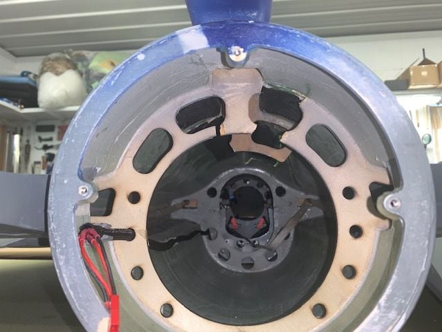
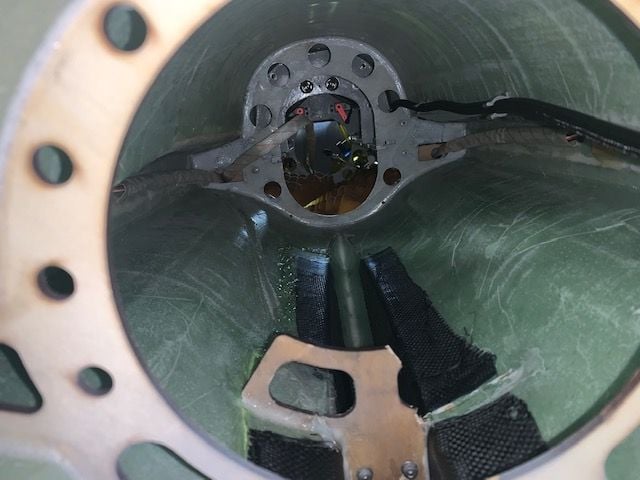
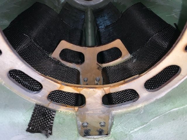
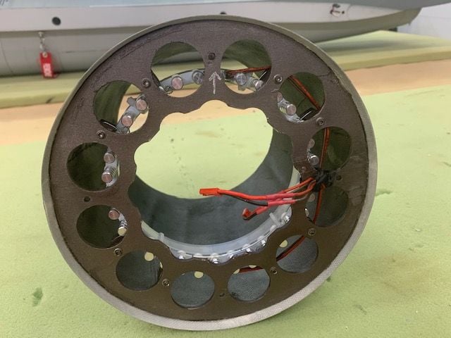
im amazed that lightening holes so large and close to the vertical axis of the V. Stab were used on the rear bulkhead. If it was mine, i wouldn�t of used any lightening holes between the 9 through to the 3 o�clock position. The marginal weight savings for the reduction in strength just isnt worth it, imo.
im amazed that lightening holes so large and close to the vertical axis of the V. Stab were used on the rear bulkhead. If it was mine, i wouldn�t of used any lightening holes between the 9 through to the 3 o�clock position. The marginal weight savings for the reduction in strength just isnt worth it, imo.
07-07-2021, 09:21 AM
#294
Thread Starter
My Feedback: (20)
Hi Thomas,
Yes, I agree. I had planned to double the formers but elected not to after the CF made the skin pretty stiff, especially the double layer outside the front former. I would recommend more wood left in the formers at the top half also.
Gary
Yes, I agree. I had planned to double the formers but elected not to after the CF made the skin pretty stiff, especially the double layer outside the front former. I would recommend more wood left in the formers at the top half also.
Gary
The following 2 users liked this post by Viper1GJ:
invertmast (07-07-2021),
tmgreen64 (07-07-2021)
07-08-2021, 07:41 AM
#295
Hi Gary,
Just "stumbled" over this thread: great build thread!
Regarding the vertical fin former, I tend to agree with Thomas.
IMHO it's the inner part of the former - where the lower end of the vertical fin tube ends - which distrubutes most of the side loads into the fuselage i.e. during knife edge flight.
Stiffening the fuselage with sufficient carbon is a good thing as the glass fiber over the Herex/Airex is usually very thin.
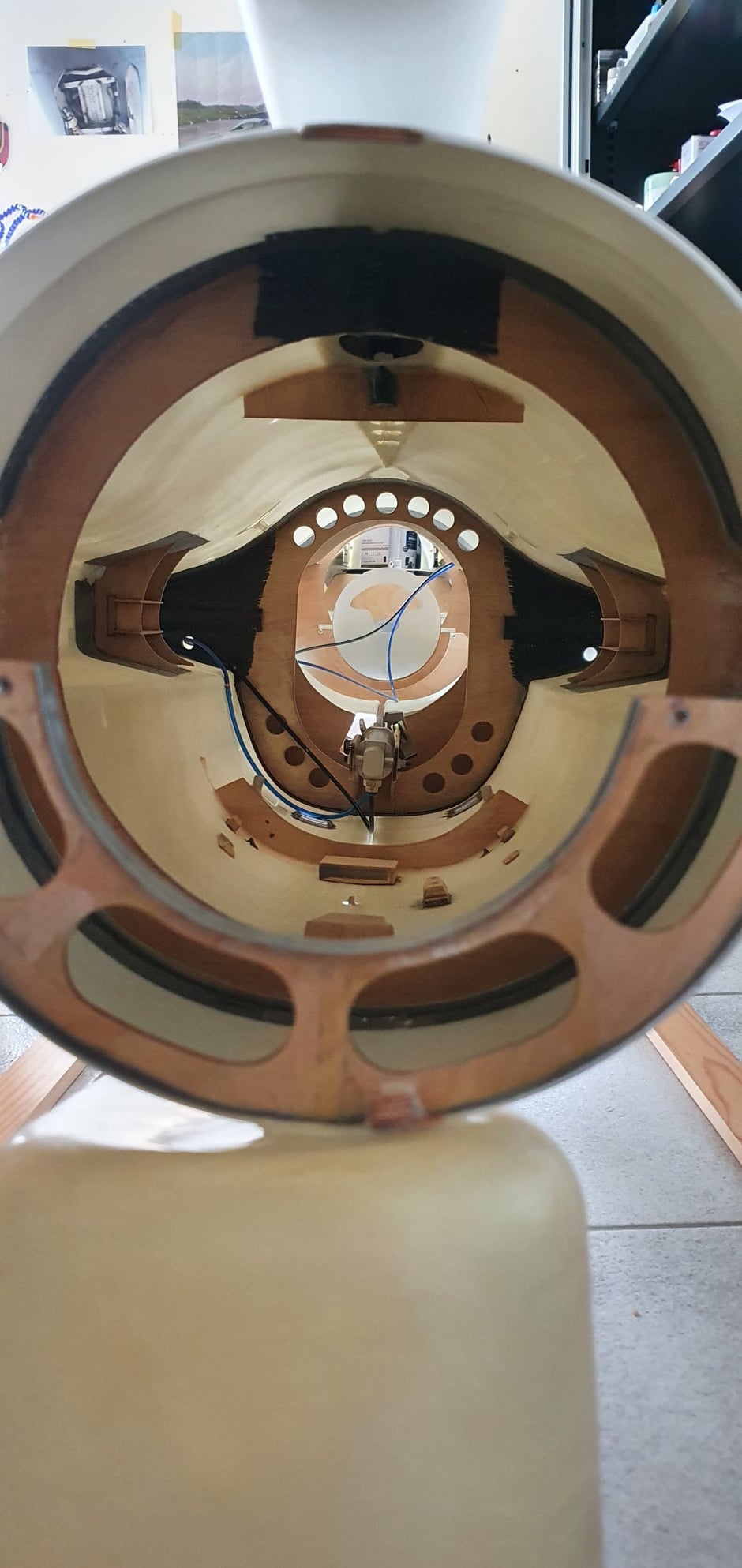
Currently, I'm working on an F-16 from Marijn (scale-jets.com) and although his F-16 is a strong traditional lay-up, his vertical fin former is a solid ring all around, see picture below.
The inside of the fuselage was molded with a 2 inch wide carbon fiber strip and the former is placed in the middle of this strip.
It's hard to judge from a picture how strong the F-16XL former is and how strong it's now with the strengthening part which you have used, but maybe a strip of carbon cloth just behind this former and beefing up the former itself would not be a bad idea.
Remco
Just "stumbled" over this thread: great build thread!
Regarding the vertical fin former, I tend to agree with Thomas.
IMHO it's the inner part of the former - where the lower end of the vertical fin tube ends - which distrubutes most of the side loads into the fuselage i.e. during knife edge flight.
Stiffening the fuselage with sufficient carbon is a good thing as the glass fiber over the Herex/Airex is usually very thin.
Currently, I'm working on an F-16 from Marijn (scale-jets.com) and although his F-16 is a strong traditional lay-up, his vertical fin former is a solid ring all around, see picture below.
The inside of the fuselage was molded with a 2 inch wide carbon fiber strip and the former is placed in the middle of this strip.
It's hard to judge from a picture how strong the F-16XL former is and how strong it's now with the strengthening part which you have used, but maybe a strip of carbon cloth just behind this former and beefing up the former itself would not be a bad idea.
Remco
Last edited by Remco45; 07-08-2021 at 07:53 AM.
The following users liked this post:
Viper1GJ (07-08-2021)
07-08-2021, 09:13 AM
#296
Thread Starter
My Feedback: (20)
Remco, Thomas,
While sitting here on vacation with "nothing to do" I've been thinking about the aft fin former. I agree that it should be stronger. I think it would be very easy to put a doubler on the back of the rear former that extended up to the screws holding the clamp on the former. That would help the weakest part of the former spread the loads into the fuse sides. Good idea.
Thanks,
Gary
The following users liked this post:
Viper1GJ (07-08-2021)
07-08-2021, 12:56 PM
#298
Thread Starter
My Feedback: (20)
Yep, vacation definitely good for some RC thinking while sitting around. I call it paying "RC dues" during the summer so I can escape to events during the rest of the year. I measure the "cost" of the days events in "servos". Today was a "good" day, only about 2 servos so far! LOL. I am blessed to have survived my military and airline flying career, have a RC supporting wife, good family with grandkids, and still be able to do jet stuff. No complaints.
Gary
Gary
Last edited by Viper1GJ; 07-08-2021 at 01:04 PM.

The following users liked this post:
Viper1GJ (07-08-2021)
07-13-2021, 01:50 PM
#300
Thread Starter
My Feedback: (20)
Rear vertical fin former doubler

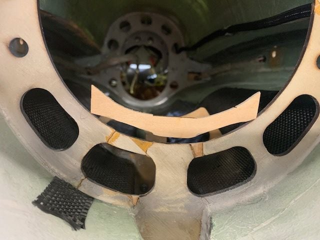
I finally got some shop time after being away for a week. I decided to make the rear former doubler as suggested by Remco45 and Invertmast. A pattern maker was used to get the curve of the outside of the fuse.
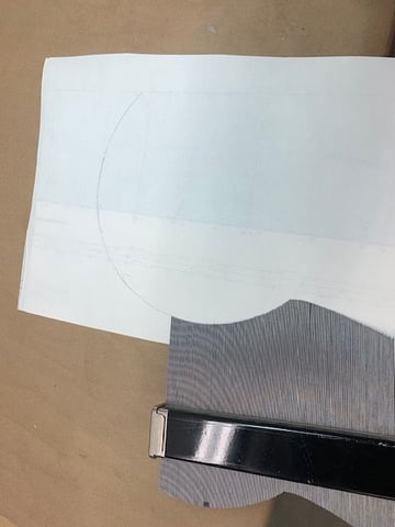
Curve transfered to paper.
Paper pattern cut out
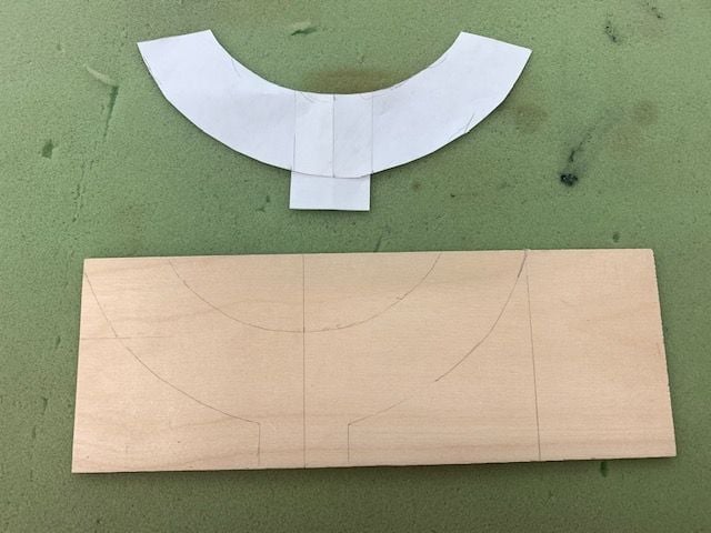
Pattern transferred to 1/8" plywood
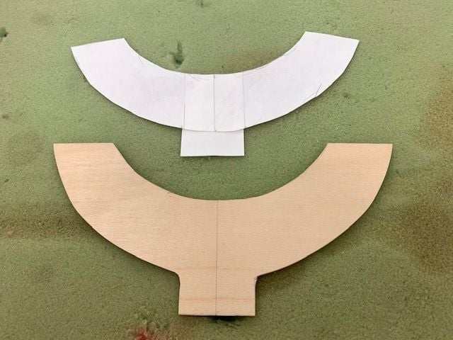
Plywood cut
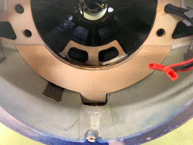
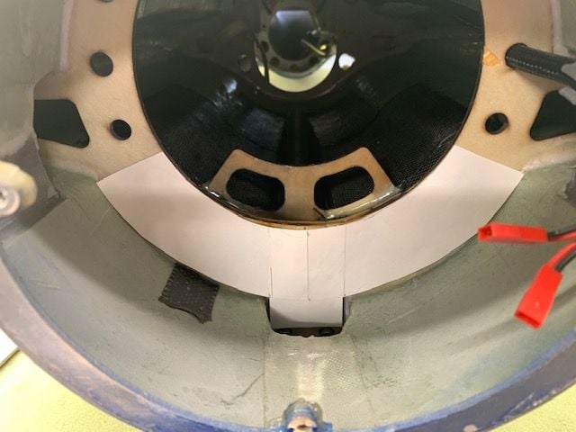
Dry fit to rear fin former
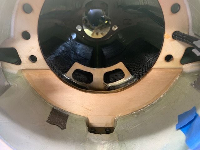
Six10 epoxy used to glue in former and make edge fillets. Mod added 19 grams plus epoxy.
I finally got some shop time after being away for a week. I decided to make the rear former doubler as suggested by Remco45 and Invertmast. A pattern maker was used to get the curve of the outside of the fuse.
Curve transfered to paper.
Paper pattern cut out
Pattern transferred to 1/8" plywood
Plywood cut
Dry fit to rear fin former
Six10 epoxy used to glue in former and make edge fillets. Mod added 19 grams plus epoxy.