


F-16XL ARF by Global Knight Models from Global Jet Club
 04-30-2021, 05:23 PM
#176

Thread Starter
My Feedback: (20)
Airframe assembly continued...

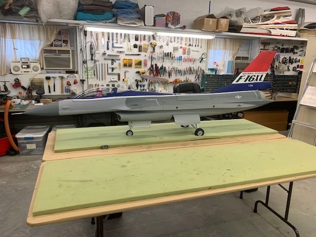
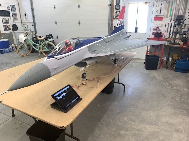
I dropped the gear and got the fuse standing up for the first time.
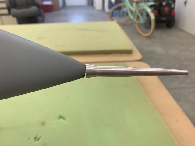
Some fit and finish issues on the pitot tube screw and the radome. The base of the pitot tube is larger than the front of the radome. Looks goofy. Also the front face of the radom is not square with the pitot tube screw and shows a gap. This should be fixed at the factory.

More grey overspray at the fuse joint line. Just sloppy paint work.
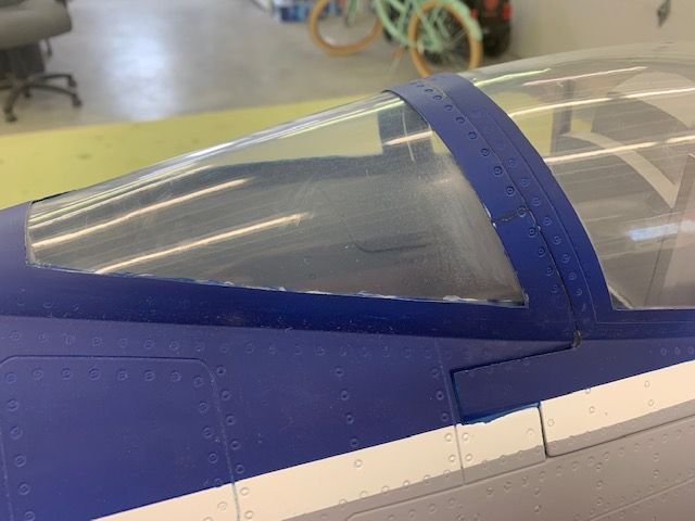
Grey overspray on canopy. Not sure if there is a way to clean this off with out destroying the canopy plastic. Suggestions appreciated.
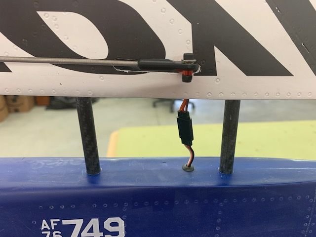
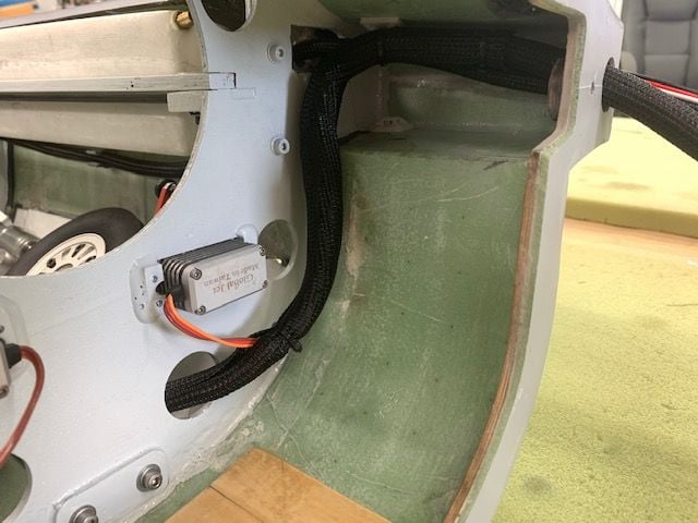
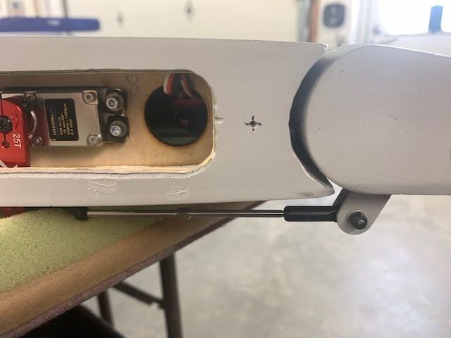
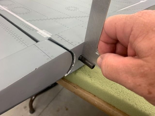
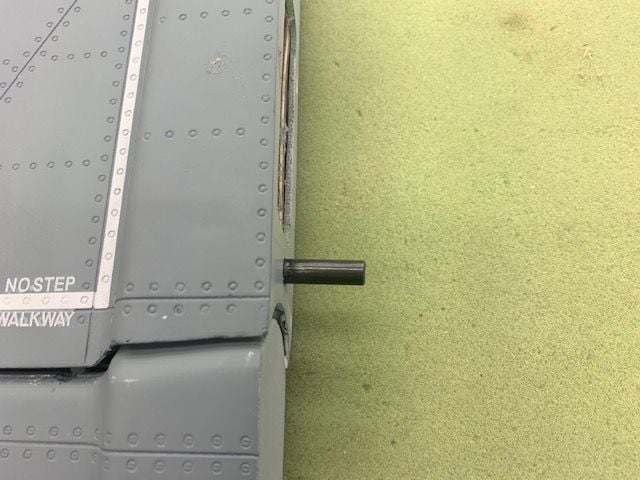
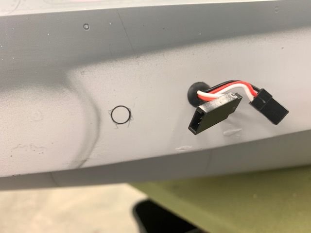
I attached the vertical fin and rudder servo plug
After the fin would not seat on the dorsal fin I discovered the wire was puckered up in the servo arm slot.

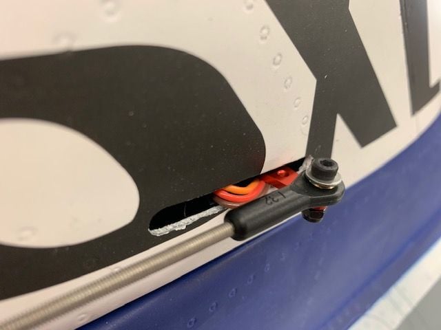
Then I realized the servo wire comes up just below the servo arm and there is no where to tuck the wire.

So I had to remove the servo and run the wire to the rear of the servo case. I recommend the servo wire in the dorsal fin be moved aft about 1.5" to avoid conflict with the servo arm.
I dropped the gear and got the fuse standing up for the first time.
Some fit and finish issues on the pitot tube screw and the radome. The base of the pitot tube is larger than the front of the radome. Looks goofy. Also the front face of the radom is not square with the pitot tube screw and shows a gap. This should be fixed at the factory.
More grey overspray at the fuse joint line. Just sloppy paint work.
Grey overspray on canopy. Not sure if there is a way to clean this off with out destroying the canopy plastic. Suggestions appreciated.
I attached the vertical fin and rudder servo plug
After the fin would not seat on the dorsal fin I discovered the wire was puckered up in the servo arm slot.
Then I realized the servo wire comes up just below the servo arm and there is no where to tuck the wire.
So I had to remove the servo and run the wire to the rear of the servo case. I recommend the servo wire in the dorsal fin be moved aft about 1.5" to avoid conflict with the servo arm.
 04-30-2021, 05:39 PM
#177
My pitot tube is a little different, maybe you can cut that funnel end off it, if there is enough thread up in there. as for the canopy, try to wax it off, maybe some motor cycle visor cleaner. Some of those F16 crew chief should know, The USAF send them to school on how to polish the real deal.
04-30-2021, 05:53 PM
#178
Thread Starter
My Feedback: (20)
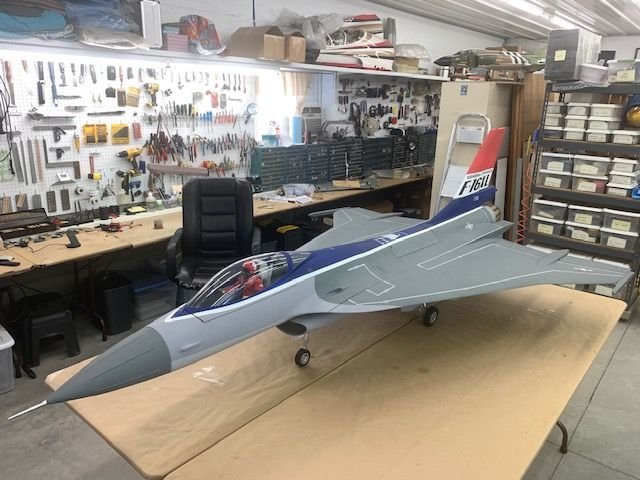
Wings on!
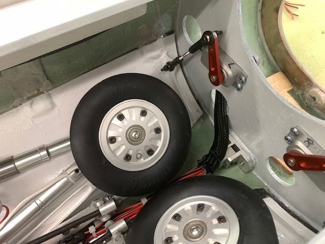
Finally got the vertical fin installed and clamped on. Clamp screws worked good. I noticed the main wheels are tilted in at the bottom when extended. I see no way to adjust the angle of the wheel. If flown on pavement I think the outside edge of the tires would quickly wear.
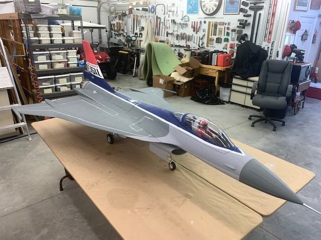
Got wings installed and clamp screws worked well here also.
Happy snaps with wings on.

The nose up angle of the missile rails really looks goofy. The missile rail should have a slightly front end down angle. I may try to fix that before flying if time allows but it's not simple because the missile rail is the outside hinge pivot point for the aileron. This also shoud be corrected at he factory for future production.
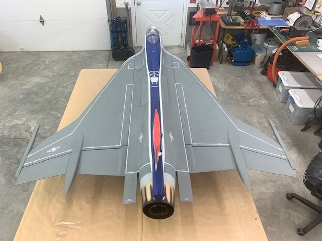
Top view looks really cool. I really loo forward to flying this jet.

I found that the trailing edge of the root rib of both wings will move up and down about 5mm with just a little push. The trailing edge of the wing will have to have an anti rotation pin before flying. This must be done for future production.
I spent about an hour doing musical chairs with equipment on the Xicoy CG machine. The measurements between the fuse part line and the gear provided in the build guide for the recommended CG were exactly the same on this model. I found that it would be quite nose heavy with batteries in the nose. With all the radio components in the traditional location under the cockpit I found I could move the batteries from the back of the front fuse to the nose and shift he CG about 1.5 " I also found that I could be at or forward of the recommended CG if the air trap, pump, and turbine DRU box were mounted above the front tank in the aft fuse section. This would allow me to keep all the wet fuel stuff still connected in the rear section when the front section was removed. So that is the plan for now. I remember Josh told me that F900's jet flew poorly and was tail heavy at the recommended CG so I want to be able to move batteries to get forward of the recommended CG for the first flights.
Finally got the vertical fin installed and clamped on. Clamp screws worked good. I noticed the main wheels are tilted in at the bottom when extended. I see no way to adjust the angle of the wheel. If flown on pavement I think the outside edge of the tires would quickly wear.
Got wings installed and clamp screws worked well here also.
Happy snaps with wings on.
The nose up angle of the missile rails really looks goofy. The missile rail should have a slightly front end down angle. I may try to fix that before flying if time allows but it's not simple because the missile rail is the outside hinge pivot point for the aileron. This also shoud be corrected at he factory for future production.
Top view looks really cool. I really loo forward to flying this jet.
I found that the trailing edge of the root rib of both wings will move up and down about 5mm with just a little push. The trailing edge of the wing will have to have an anti rotation pin before flying. This must be done for future production.
I spent about an hour doing musical chairs with equipment on the Xicoy CG machine. The measurements between the fuse part line and the gear provided in the build guide for the recommended CG were exactly the same on this model. I found that it would be quite nose heavy with batteries in the nose. With all the radio components in the traditional location under the cockpit I found I could move the batteries from the back of the front fuse to the nose and shift he CG about 1.5 " I also found that I could be at or forward of the recommended CG if the air trap, pump, and turbine DRU box were mounted above the front tank in the aft fuse section. This would allow me to keep all the wet fuel stuff still connected in the rear section when the front section was removed. So that is the plan for now. I remember Josh told me that F900's jet flew poorly and was tail heavy at the recommended CG so I want to be able to move batteries to get forward of the recommended CG for the first flights.
Last edited by Viper1GJ; 04-30-2021 at 05:58 PM.
04-30-2021, 06:06 PM
#179
Thread Starter
My Feedback: (20)
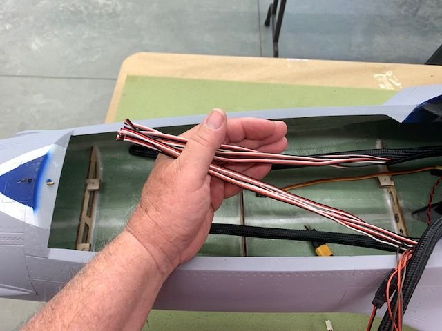
Taming the wires!
I decided I had to do something with all the wire bundles so I used slotted flex sleeve to enclose wire bundles. I started with the gear bundle at the front former.
Gear cables come forward and pick up the left main gear door servo wire and up and out the front. This section will have the front tank, air trap, pump, and DRU box so I needed to get the wires tucked in and out of the way.
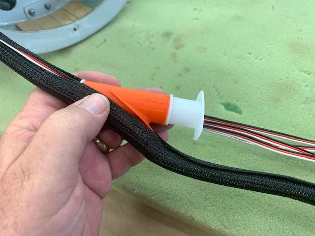
I got this cool tool from Ultimate Jets. Makes tucking the wires in the sleeve easy.
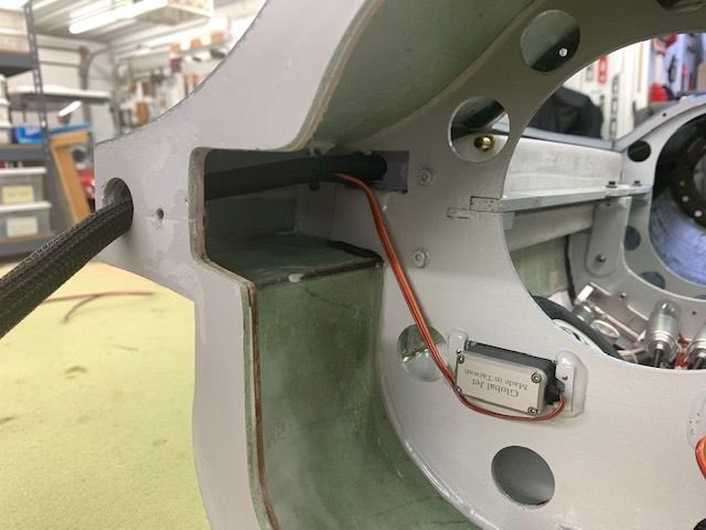
Right side servo wires and right main gear servo wires come out the right side

Left servo and AB LED wires to go...
I decided I had to do something with all the wire bundles so I used slotted flex sleeve to enclose wire bundles. I started with the gear bundle at the front former.
Gear cables come forward and pick up the left main gear door servo wire and up and out the front. This section will have the front tank, air trap, pump, and DRU box so I needed to get the wires tucked in and out of the way.
I got this cool tool from Ultimate Jets. Makes tucking the wires in the sleeve easy.
Right side servo wires and right main gear servo wires come out the right side
Left servo and AB LED wires to go...
05-01-2021, 06:44 AM
#180
I know that plastic modelers used to use toothpaste to polish the canopies with.......you might try that, applied w/ a Q-tip to remove the overspray........very carefully! Followed by a polish to clean it up.
05-01-2021, 04:56 PM
#183
Plastic is strong enough to hold most chemicals. I quick pass with some turpentine might do it but don't trust acetone Lol. That can fog it up sometimes if you scrub with it. But D alcohol is very safe I find. I always seem to get paint or epoxy on my canopies but I never have had a problem with D alcohol. There are plastic cleaners and polishers for headlights that are safe to. The problem though can be from the paint they used etching into the plastic. Then plastic polish might be your friend there but sometimes nothing works if that's the case. Then you start thinking about painting the inside a grey or black when all else fails.
 05-03-2021, 05:14 PM
#187
Thread Starter
My Feedback: (20)
Installing fuel system
I concluded after my weight and balance exercise to mount the entire fuel system in the aft fuse. This keeps all the wet parts connected and together in the rear fuse. This makes taking the fuse apart much easier since there are only wires to disconnect.
Dry fitting the air trap. I like the Digitech air trap mounts because they allow the tank to be rotated to any angle. This made it easy to mount the air trap on the ceiling and still have the tubes in the correct positions.

Glue positions marked
Blind nuts used to attach the air trap to the mounts
Masking tape keeps epoxy out of the bolt threads
Fuel pump mounted in similar fashion
Fuel pump epoxied in place
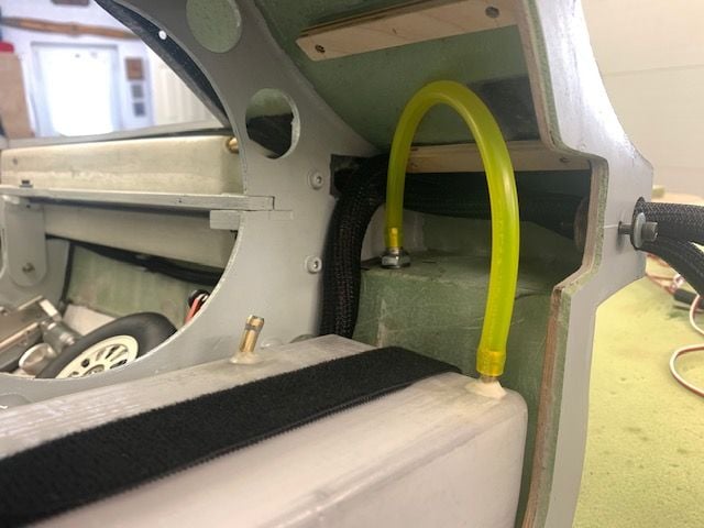
Front tank vent connected to overflow tank vent fitting
1/16" craft foam I stole from my wife's craft room placed on tank mount for some padding
Tank strapped in and connected to left saddle tank. Safety wire on tubing connections
Fuel system in ceiling of aft fuse section. I ran out of 3/16" ID Tygon. I needed 5" more to connect air trap to pump. More Tygon on the way.
I concluded after my weight and balance exercise to mount the entire fuel system in the aft fuse. This keeps all the wet parts connected and together in the rear fuse. This makes taking the fuse apart much easier since there are only wires to disconnect.
Dry fitting the air trap. I like the Digitech air trap mounts because they allow the tank to be rotated to any angle. This made it easy to mount the air trap on the ceiling and still have the tubes in the correct positions.
Glue positions marked
Blind nuts used to attach the air trap to the mounts
Masking tape keeps epoxy out of the bolt threads
Fuel pump mounted in similar fashion
Fuel pump epoxied in place
Front tank vent connected to overflow tank vent fitting
1/16" craft foam I stole from my wife's craft room placed on tank mount for some padding
Tank strapped in and connected to left saddle tank. Safety wire on tubing connections
Fuel system in ceiling of aft fuse section. I ran out of 3/16" ID Tygon. I needed 5" more to connect air trap to pump. More Tygon on the way.
05-03-2021, 05:45 PM
#188
Thread Starter
My Feedback: (20)
Wing trailing edge anti rotation pins installed
After seeing he flexing of the trailing edge of the wing I decided to install anti rotation pins on the trailing edge before I flew the jet.
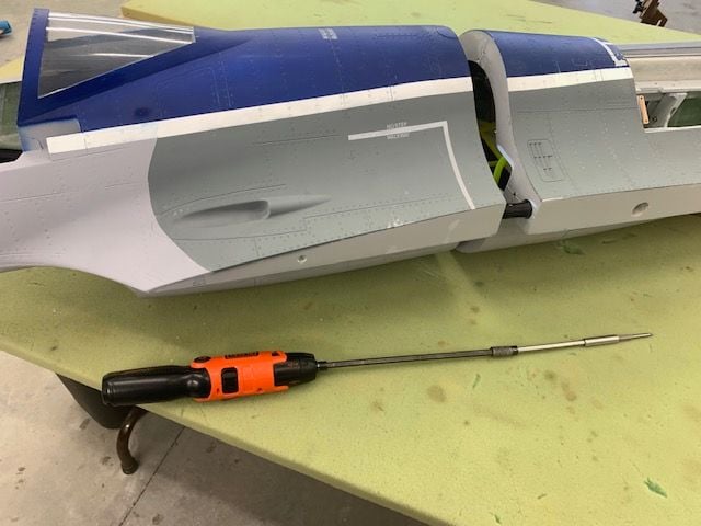
I found out this powered screwdriver with extensions makes it a lot easier to assemble and disassemble the fuse sections. I attached the forward fuse before before working on the trailing edge pins. I wanted the leading edge pins engaged to insure the wing alignment would be correct.
Position of trailing edge pin marked on each wing.

The 8mm carbon pin will go into the wood behind the root rib. This is good.

Holes drilled. I started with a 2mm bit and worked up to 8mm
8mm carbon tube pins tacked in with medium CA and squared with root rib.
Pin tacked in ready to fit to fuse

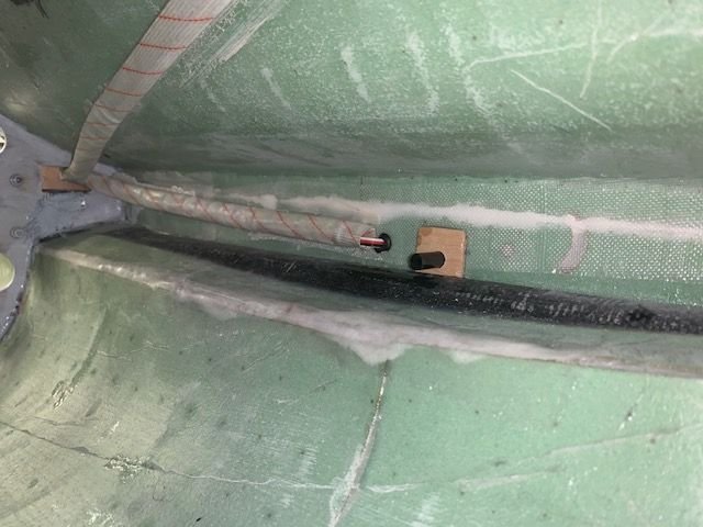
Wing attached to the fuse and pin location marked on fuse side
Holes were cut where pin enters the fuse side just slightly oversize.
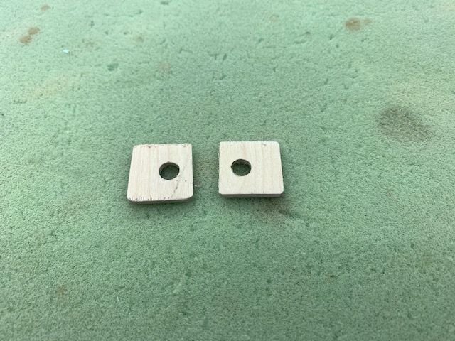
1/8" plywood square donuts made and drilled for 8mm pins.
Vaseline was applied to the carbon pins. 5 min epoxy applied to the plywood donut. Then the plywood is placed on pin and pushed into the fuse side. After alignment is checked Six10 thickened epoxy will secure the carbon pins into the wings and the plywood donuts to he inside of the fuse sides.
After seeing he flexing of the trailing edge of the wing I decided to install anti rotation pins on the trailing edge before I flew the jet.
I found out this powered screwdriver with extensions makes it a lot easier to assemble and disassemble the fuse sections. I attached the forward fuse before before working on the trailing edge pins. I wanted the leading edge pins engaged to insure the wing alignment would be correct.
Position of trailing edge pin marked on each wing.
The 8mm carbon pin will go into the wood behind the root rib. This is good.
Holes drilled. I started with a 2mm bit and worked up to 8mm
8mm carbon tube pins tacked in with medium CA and squared with root rib.
Pin tacked in ready to fit to fuse
Wing attached to the fuse and pin location marked on fuse side
Holes were cut where pin enters the fuse side just slightly oversize.
1/8" plywood square donuts made and drilled for 8mm pins.
Vaseline was applied to the carbon pins. 5 min epoxy applied to the plywood donut. Then the plywood is placed on pin and pushed into the fuse side. After alignment is checked Six10 thickened epoxy will secure the carbon pins into the wings and the plywood donuts to he inside of the fuse sides.
05-04-2021, 07:19 AM
#189

I just noticed the arc/slot in the fuselage side, behind your new anti-rotation pin. Looks like maybe they originally designed this plane to use fuse-mounted servos with direct drive slots into the root of the surface perhaps?
Did you find the .stl file for the Kingtech filter on Thingiverse? I imagine dozens of people have designed one, I just have never found one for that filter. Found one that incorporates a filter mount with a ball valve mount, but that won't work for what I'm needing. Yours would be perfect.
Did you find the .stl file for the Kingtech filter on Thingiverse? I imagine dozens of people have designed one, I just have never found one for that filter. Found one that incorporates a filter mount with a ball valve mount, but that won't work for what I'm needing. Yours would be perfect.
05-04-2021, 07:57 AM
#190

My Feedback: (53)

I just noticed the arc/slot in the fuselage side, behind your new anti-rotation pin. Looks like maybe they originally designed this plane to use fuse-mounted servos with direct drive slots into the root of the surface perhaps?
Did you find the .stl file for the Kingtech filter on Thingiverse? I imagine dozens of people have designed one, I just have never found one for that filter. Found one that incorporates a filter mount with a ball valve mount, but that won't work for what I'm needing. Yours would be perfect.
Did you find the .stl file for the Kingtech filter on Thingiverse? I imagine dozens of people have designed one, I just have never found one for that filter. Found one that incorporates a filter mount with a ball valve mount, but that won't work for what I'm needing. Yours would be perfect.
 05-04-2021, 04:39 PM
#191
Thread Starter
My Feedback: (20)
I just noticed the arc/slot in the fuselage side, behind your new anti-rotation pin. Looks like maybe they originally designed this plane to use fuse-mounted servos with direct drive slots into the root of the surface perhaps?
Did you find the .stl file for the Kingtech filter on Thingiverse? I imagine dozens of people have designed one, I just have never found one for that filter. Found one that incorporates a filter mount with a ball valve mount, but that won't work for what I'm needing. Yours would be perfect.
Did you find the .stl file for the Kingtech filter on Thingiverse? I imagine dozens of people have designed one, I just have never found one for that filter. Found one that incorporates a filter mount with a ball valve mount, but that won't work for what I'm needing. Yours would be perfect.
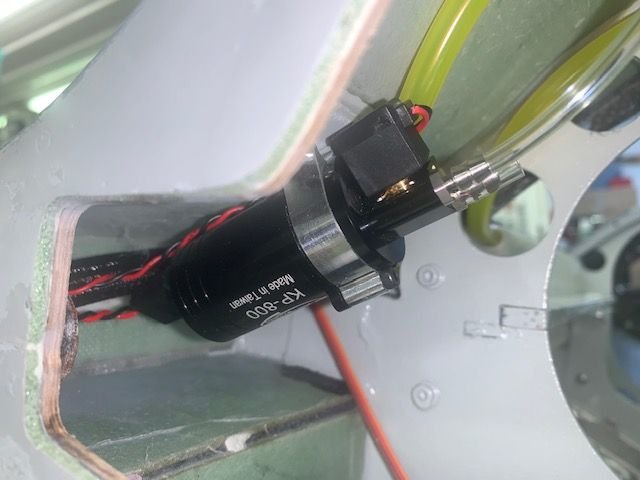
My filter bracket is a wrap around sleeve clip I got from Ultimate Jets.
Link here: https://www.ultimate-jets.net/collec...e-pycabs-clips
05-04-2021, 04:59 PM
#192
Thread Starter
My Feedback: (20)
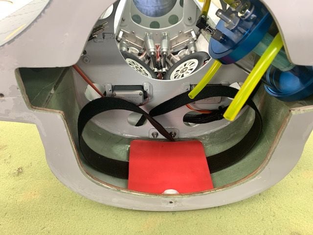
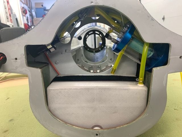
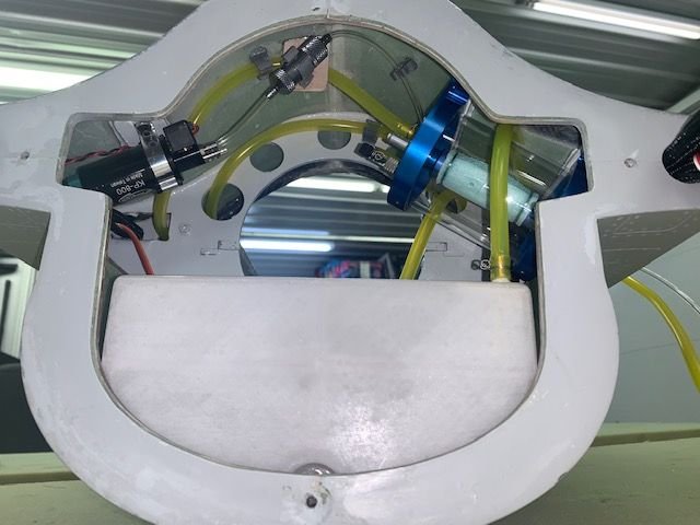
Fuel system finished up

Fuel system finished up except tubing from air trap to pump inlet.
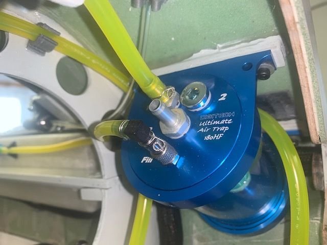
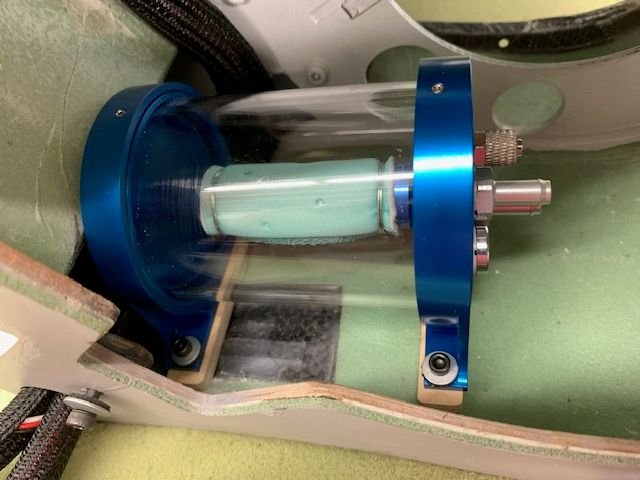
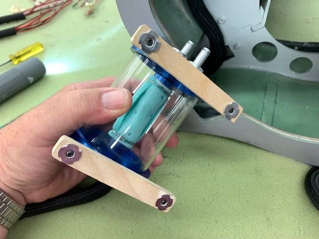
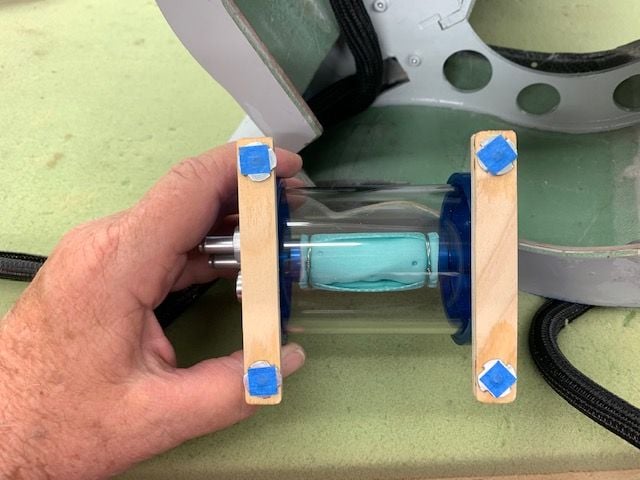
Digitec Ultimate Air Trap 180ml

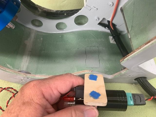
Here is the Ultimate Jets sleeve clip. Works great on the Kingtech filters. It's a loose fit so the filter can jiggle a little to dislodge air bubbles. The fuse is upside down in this photo.
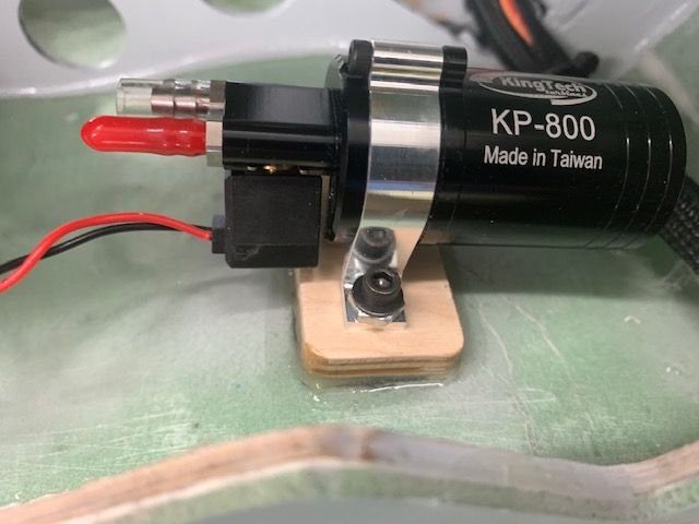
Fuel pump less connection tubing from the air trap.
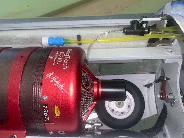
Fill tube and master fuel shutoff.
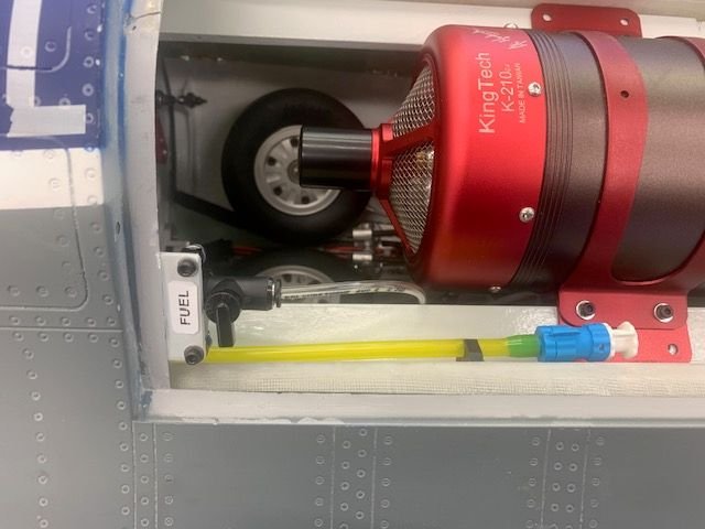
I didn't have any of the small Festo ball valve holding brackets so I used the wide one that came from Kingtech.
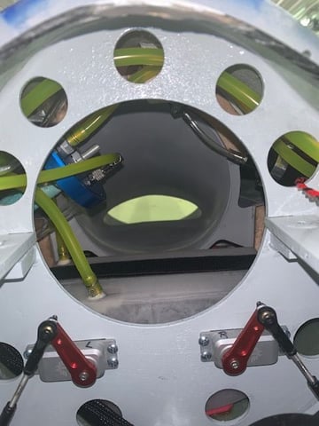
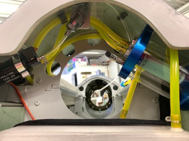
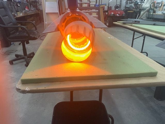
View from the front of the turbine looking for air molecules to eat!
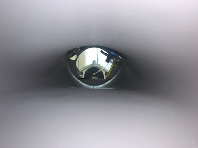
Air molecule view from front of air intake just before it's gobbled up by the turbine!
And, oh yes the new roll of 3/16" ID Tygon was delivered this afternoon just after I bolted the fuse sections together to work on the electronics. So first thing tomorrow is to crack open the fuse again and install the last 5" of tubing. Go figure!
Fuel system finished up except tubing from air trap to pump inlet.
Digitec Ultimate Air Trap 180ml
Here is the Ultimate Jets sleeve clip. Works great on the Kingtech filters. It's a loose fit so the filter can jiggle a little to dislodge air bubbles. The fuse is upside down in this photo.
Fuel pump less connection tubing from the air trap.
Fill tube and master fuel shutoff.
I didn't have any of the small Festo ball valve holding brackets so I used the wide one that came from Kingtech.
View from the front of the turbine looking for air molecules to eat!
Air molecule view from front of air intake just before it's gobbled up by the turbine!
And, oh yes the new roll of 3/16" ID Tygon was delivered this afternoon just after I bolted the fuse sections together to work on the electronics. So first thing tomorrow is to crack open the fuse again and install the last 5" of tubing. Go figure!
05-04-2021, 05:21 PM
#193
Thread Starter
My Feedback: (20)
RC Install

Mission impossible! Is this were the tape self destructs?
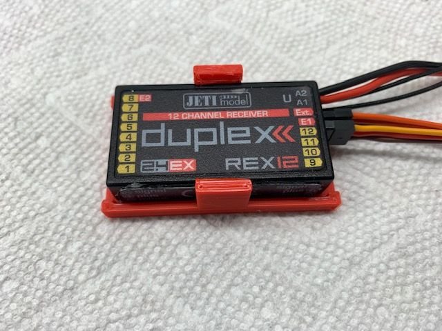
I started out keeping the 3D printer going making bling for all the little boxes.
Here's one Keith drew up for me today.

As long as I can download or get the stl file from an email I can print it. I ask my self why and quickly answered because I can!
The layout evolved with planning were I could put antennas that were not near all the carbon fiber in the forward fuse.
I added the AB LED and landing light controller to the back of the board. When I turned the CB400 around I had to completely reorganize the output map to avoid a bunch of crossover wires and make sure all the flight controls were in CortexPro stabilized slots. My plan is all the connectors between boxes will go under the board. All of the big cable looms will have to be on sides above the board. To be continued...
Mission impossible! Is this were the tape self destructs?
I started out keeping the 3D printer going making bling for all the little boxes.
Here's one Keith drew up for me today.
As long as I can download or get the stl file from an email I can print it. I ask my self why and quickly answered because I can!
The layout evolved with planning were I could put antennas that were not near all the carbon fiber in the forward fuse.
I added the AB LED and landing light controller to the back of the board. When I turned the CB400 around I had to completely reorganize the output map to avoid a bunch of crossover wires and make sure all the flight controls were in CortexPro stabilized slots. My plan is all the connectors between boxes will go under the board. All of the big cable looms will have to be on sides above the board. To be continued...
Last edited by Viper1GJ; 05-04-2021 at 05:26 PM.
05-04-2021, 06:00 PM
#194
I think the arc you are talking about is paint overspray when they sprayed the top dark grey with the wings attached. I don't think they planned direct drive from the fuse. There is a servo pocket cut out molded into the bottom of each wing where the outboard aileron servo could go in the wing.
 05-05-2021, 04:06 PM
#195
Thread Starter
My Feedback: (20)
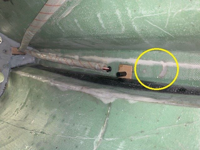
You are correct. I never saw the marks on the inside before. They are on both sides in the same spot. It looks like something in the molding process was planned and then glassed over. If you shine a light from the inside or outside the hole and arc are clearly visible but I have no clue what they are for. Good observation.
Gary
05-05-2021, 04:19 PM
#196
Thread Starter
My Feedback: (20)
RC install continued...
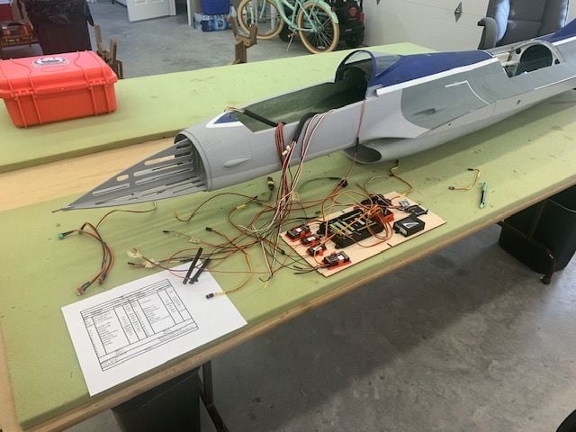
I cracked the fuse sections back apart and installed the final piece of Tygon from air trap to pump and finished the safety wiring. Fuel system is now ready for fuel. I reattached the fuse sections and started working on the equipment tray.
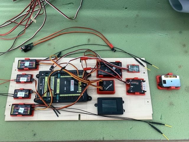
Final equipment tray layout. I kept the 3D printer busy making the part holders. The turbine DRM is not on the tray because the cable from the DRM to turbine is not long enough and I don't want to mess with making it longer. The airspeed module location (seen above the tray) is TBD pending mounting the pitot tube in the scale air data probe location on the lower left side of the nose just behind the radome. Next is to cut wiring holes, mount everytining, and hook it all up.
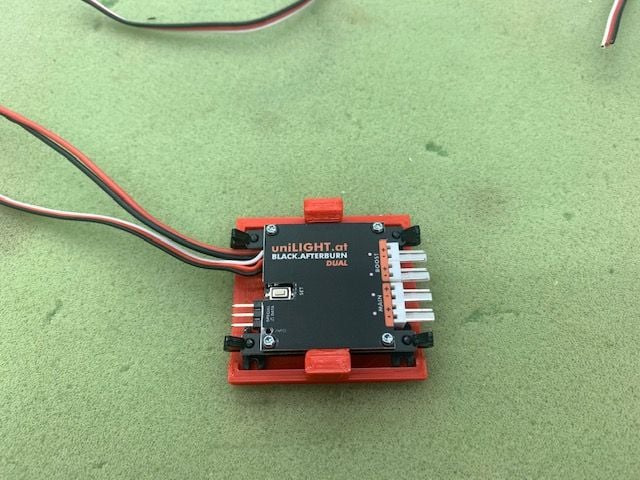
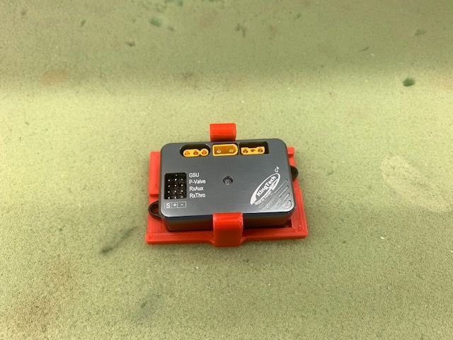
Minor victory for 3D printer novice, I modified a receiver holder to fit the AB LED light controller.
I cracked the fuse sections back apart and installed the final piece of Tygon from air trap to pump and finished the safety wiring. Fuel system is now ready for fuel. I reattached the fuse sections and started working on the equipment tray.
Final equipment tray layout. I kept the 3D printer busy making the part holders. The turbine DRM is not on the tray because the cable from the DRM to turbine is not long enough and I don't want to mess with making it longer. The airspeed module location (seen above the tray) is TBD pending mounting the pitot tube in the scale air data probe location on the lower left side of the nose just behind the radome. Next is to cut wiring holes, mount everytining, and hook it all up.
Minor victory for 3D printer novice, I modified a receiver holder to fit the AB LED light controller.
05-07-2021, 03:16 PM
#197
Thread Starter
My Feedback: (20)
More RC install...
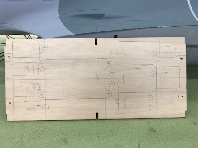
The plan!
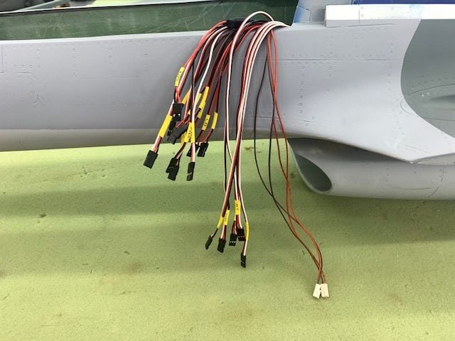
Big moment here. I finally had to make the decision to cut the wires. No going back now!

Let the crimping party begin. 1 down, 40 more to go...
Party's over! I had to trace each lead to figure out what label went on it. So far everything works.
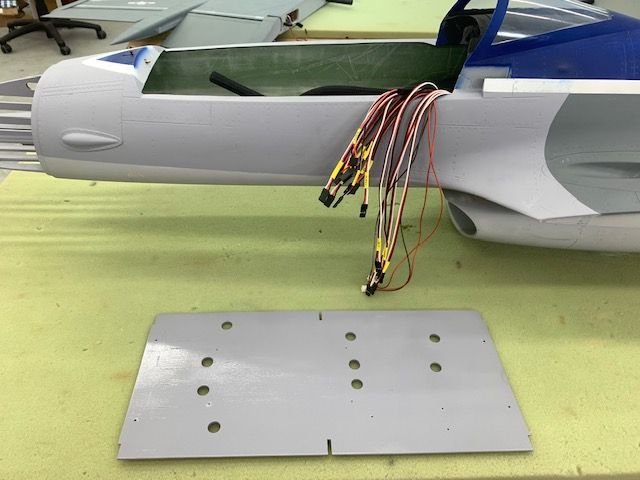
Equipment tray painted. Next is to get everything mounted and connected on the tray. Then hook up the servo leads.

Great news today from GJC. The decals arrived from China and will ship to me next week. Hopefully I can get everything ready for FIF in 2 weeks. Thanks Mike and Ralph!
The plan!
Big moment here. I finally had to make the decision to cut the wires. No going back now!
Let the crimping party begin. 1 down, 40 more to go...
Party's over! I had to trace each lead to figure out what label went on it. So far everything works.
Equipment tray painted. Next is to get everything mounted and connected on the tray. Then hook up the servo leads.
Great news today from GJC. The decals arrived from China and will ship to me next week. Hopefully I can get everything ready for FIF in 2 weeks. Thanks Mike and Ralph!
Last edited by Viper1GJ; 05-07-2021 at 03:19 PM.
05-08-2021, 06:27 PM
#199
Thread Starter
My Feedback: (20)
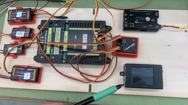
RC equipment tray testing
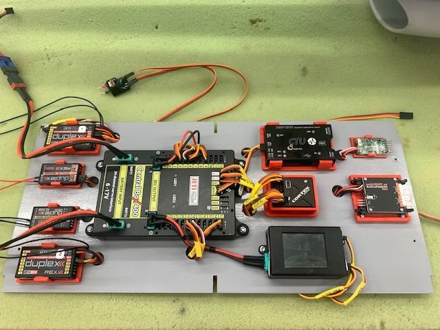
I got he tray assembled and hooked up. I made power cables for the gear, lights, and AB LED controllers. Everything actually worked. I labeled all the jumper wires so If I have to take something out to work on it will be easy to hook everything back up.
Pondus asked "Why make a 3D printed holder for the Unilight controller when it sits in the mount with it's own mounting brackets?" There is no reason for it except to have a red base like the rest of the little boxes. Same for the CortexPro. Pure bling only! Plus I was excited like a 3 year old that just learned how to open the cookie jar by himself after I was able to adjust an existing file to make a different size base. I cant do CAD yet so I was just playing with the 3D printer.

I hooked up the board to test the turbine, AB lights, and landing lights.

The only problem I had was the landing lights. They come on and can be switched on and off with the manual switch on the control board but I can not get any RC control of them with the radio, I'm getting signal out of the CB 400 that will work a servo but it will not work the lights. I just gave up on it for now and will leave them off till I can get some help with the control or a replacement. There were no instructions at all so I got some tips from Joshua but no luck.
The AB light system works great. The landing gear system is next. I got a Xicoy LG15 controller from a friend and have to program it for the JP gear. If anybody has some settings for JP gear motors please let me know. I built a wire harness to test the gear through my Hanger 9 ammeter to get the max amp settings and cycle times.
I got he tray assembled and hooked up. I made power cables for the gear, lights, and AB LED controllers. Everything actually worked. I labeled all the jumper wires so If I have to take something out to work on it will be easy to hook everything back up.
Pondus asked "Why make a 3D printed holder for the Unilight controller when it sits in the mount with it's own mounting brackets?" There is no reason for it except to have a red base like the rest of the little boxes. Same for the CortexPro. Pure bling only! Plus I was excited like a 3 year old that just learned how to open the cookie jar by himself after I was able to adjust an existing file to make a different size base. I cant do CAD yet so I was just playing with the 3D printer.
I hooked up the board to test the turbine, AB lights, and landing lights.
The only problem I had was the landing lights. They come on and can be switched on and off with the manual switch on the control board but I can not get any RC control of them with the radio, I'm getting signal out of the CB 400 that will work a servo but it will not work the lights. I just gave up on it for now and will leave them off till I can get some help with the control or a replacement. There were no instructions at all so I got some tips from Joshua but no luck.
The AB light system works great. The landing gear system is next. I got a Xicoy LG15 controller from a friend and have to program it for the JP gear. If anybody has some settings for JP gear motors please let me know. I built a wire harness to test the gear through my Hanger 9 ammeter to get the max amp settings and cycle times.
05-09-2021, 03:41 AM
#200
My Feedback: (53)
RC equipment tray testing
I got he tray assembled and hooked up. I made power cables for the gear, lights, and AB LED controllers. Everything actually worked. I labeled all the jumper wires so If I have to take something out to work on it will be easy to hook everything back up.
Pondus asked "Why make a 3D printed holder for the Unilight controller when it sits in the mount with it's own mounting brackets?" There is no reason for it except to have a red base like the rest of the little boxes. Same for the CortexPro. Pure bling only! Plus I was excited like a 3 year old that just learned how to open the cookie jar by himself after I was able to adjust an existing file to make a different size base. I cant do CAD yet so I was just playing with the 3D printer.
I hooked up the board to test the turbine, AB lights, and landing lights.
The only problem I had was the landing lights. They come on and can be switched on and off with the manual switch on the control board but I can not get any RC control of them with the radio, I'm getting signal out of the CB 400 that will work a servo but it will not work the lights. I just gave up on it for now and will leave them off till I can get some help with the control or a replacement. There were no instructions at all so I got some tips from Joshua but no luck.
The AB light system works great. The landing gear system is next. I got a Xicoy LG15 controller from a friend and have to program it for the JP gear. If anybody has some settings for JP gear motors please let me know. I built a wire harness to test the gear through my Hanger 9 ammeter to get the max amp settings and cycle times.