


Tamyia M51 Super Sherman the right way, with a cast hull
 05-15-2021, 08:48 AM
#26

Thread Starter

I was successful at making the tamiya speaker fit under the nick A1 hull with the help of the belt sander so that meant i needed to find a new place for the Hl rotation unit.
Tamiyas rotation motor as many of you know fits nicely inside the turret ring but it is less robust than the HL one and going back to how I said I looked at all 3 options, (Howiter ring conversion on the turret, M51 ring conversion on the hull, and HL I went with HL. All 3 were going to be a ton of work and this particular hull had a little wave in it around the barbett ring so I opted for the HL for durability. Well I sure wish those HL boxes were smaller. I spent a few hours placing it around and testing the speaker fit and no way to put it behind the turret so It had to go in the co drivers hatch. Not really a problem just a lot of work to make it fit. I placed it, slightly drilled holes and put plastic pins in plastic tubing, down into the drilled holes for extra sheer strength. After it was all in and tested, I bedded it with autobody bondo for extra stability. One more to do...


Tamiyas rotation motor as many of you know fits nicely inside the turret ring but it is less robust than the HL one and going back to how I said I looked at all 3 options, (Howiter ring conversion on the turret, M51 ring conversion on the hull, and HL I went with HL. All 3 were going to be a ton of work and this particular hull had a little wave in it around the barbett ring so I opted for the HL for durability. Well I sure wish those HL boxes were smaller. I spent a few hours placing it around and testing the speaker fit and no way to put it behind the turret so It had to go in the co drivers hatch. Not really a problem just a lot of work to make it fit. I placed it, slightly drilled holes and put plastic pins in plastic tubing, down into the drilled holes for extra sheer strength. After it was all in and tested, I bedded it with autobody bondo for extra stability. One more to do...
 05-26-2021, 08:45 PM
#27
Thread Starter
Work continues on the older of the fraternal twins while I wait for some parts for the recoil on the other.
With the turret operational parts completed I moved on to detailing and a light texturing. This time rather than use a dish sponge to apply the body putty for texturing I just used my finger and dabbed / smeared it on lightly then sanded gently when dry. I like how it came out its going to be very suttle I think so Im looking forward to getting some primer on it and then gluing on the spare track blocks.


With the turret operational parts completed I moved on to detailing and a light texturing. This time rather than use a dish sponge to apply the body putty for texturing I just used my finger and dabbed / smeared it on lightly then sanded gently when dry. I like how it came out its going to be very suttle I think so Im looking forward to getting some primer on it and then gluing on the spare track blocks.
Last edited by RichJohnson; 05-26-2021 at 08:49 PM.
05-31-2021, 06:51 AM
#29
Thread Starter
Engine decks from shapeways.
The bracket on the idler mounts is a brace from shapeways. I thought I would try it out. I had to cut the bottom out of the speaker to use it when I thought about it longer I should have just cut the bottom of the connecting bracket apart. I dont know exactly why its there instead of being two seperate braces but I figure it must have something to do with keeping the two aligned square.
The bracket on the idler mounts is a brace from shapeways. I thought I would try it out. I had to cut the bottom out of the speaker to use it when I thought about it longer I should have just cut the bottom of the connecting bracket apart. I dont know exactly why its there instead of being two seperate braces but I figure it must have something to do with keeping the two aligned square.
05-31-2021, 10:49 AM
#30
I used the same idler brace on my Sherman and cut the bottom of the speaker also, but mine is the metal one so it would've been much harder to cut the brace.

 05-31-2021, 08:57 PM
#32
06-01-2021, 05:13 AM
#33
 06-01-2021, 12:25 PM
#34
06-12-2021, 08:37 AM
#35
Thread Starter
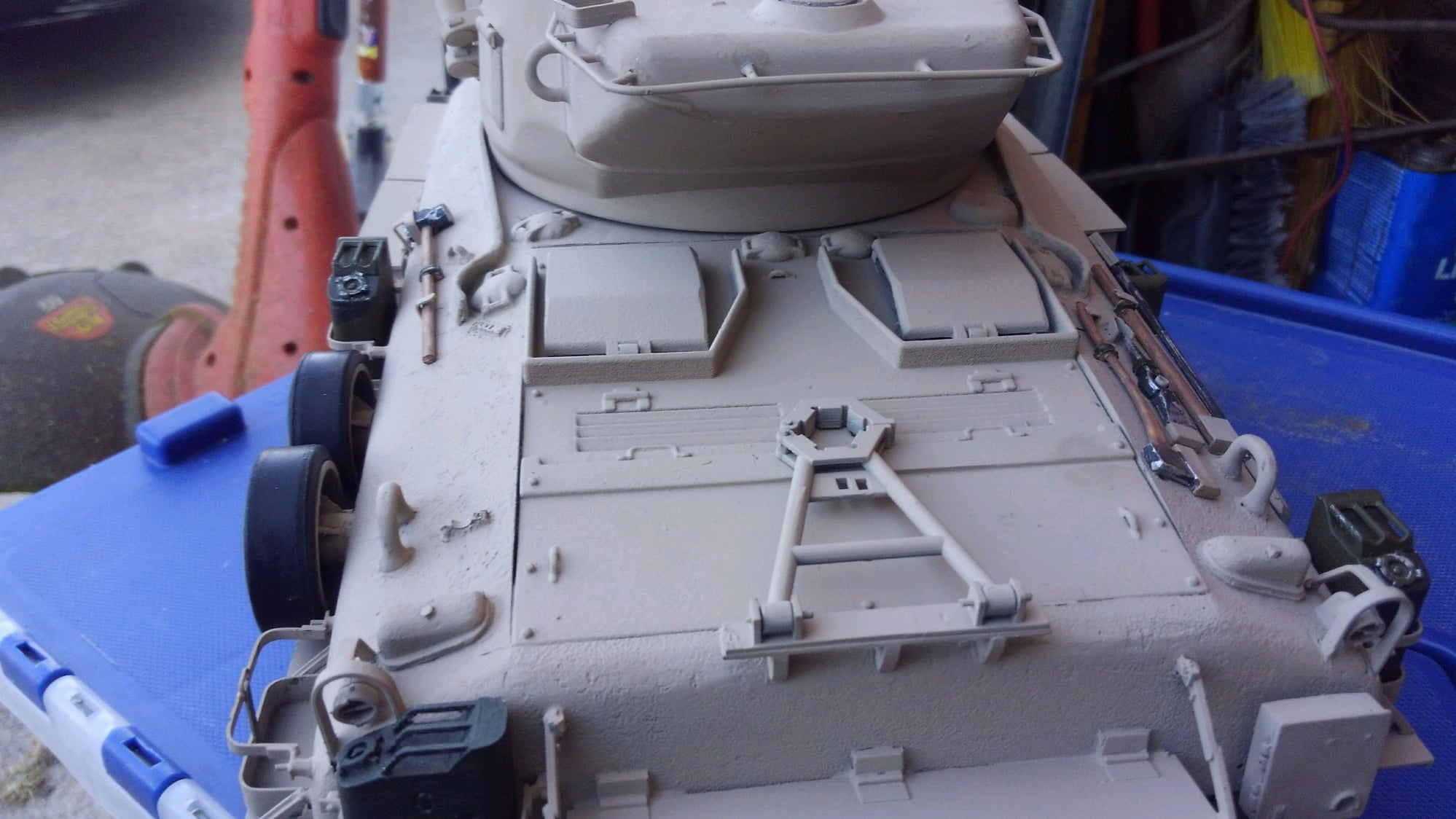
Just an update on progress.
The "A " tank on the left will be a 1973 Yom Kipur war variant engine deck and exhaust while the right tank, the "B" tank will be a 1967 6 day war era tank with a plain diesel engine deck.
I have learned recently that the large stowage bin typically seen on the rear of M51s was not installed until the final round of upgrades in 1974-75 ish which is the same time improvements were made to the final version of the engine deck making the exhaust come out the top and duct sideways and the exhaust pipe on the rear of the tank was blanked over.
Most shermans were still in reserve units at this time so most received these upgrades so nearly all tanks sold off or on display have the last variant of upgrades so tracking when stuff was added and changed is tough. Combine this with the A and B variant of the two depots that built the tanks makes for vary interesting subject matter. What I call the A tank is the two tool box design with the tracks on the turret and the large tube frame travel lock. What I call the B tank is a mirror of the M50 design with just one tool box and the tracks mounted in front of them on the hull with a smaller M50 style travel lock, this depot logically as also the probably the first one that set up all the M50s until a second was opened to build the large number of M51s years later based on what Ive read.
While it does not look like a lot of progress this is countless hours of work for me.
The following users liked this post:
Super18 (06-12-2021)
06-12-2021, 04:22 PM
#37
Thread Starter
That took me a while to figure out what you were referring to. That is a very very old cardboard tray from 4, 6packs of Coke when they cam on those clear plastic fishnet things that held 6 cans. I dont think soda cans have come in those cardboard trays for an eon.
06-12-2021, 06:11 PM
#39
Say Rich can you post picks on how you did the side skirts .
Thanks
Jimmy
Thanks
Jimmy
06-12-2021, 06:45 PM
#41
Thanks
Jimmy
06-12-2021, 08:47 PM
#42
Thread Starter
Ok well i would not cut the fenders off the tamiya kit hull and glue them to the nick hull.
The Nick A1 cast hull is not perfectly straight down the sides, its a cast hull so the sides of it bow in and out gently, enough to cause issues mounting fenders. These are fenders. Remember side skirts are like sand shields and cover the rollers and track.
So the first thing I did was decide to create a shelf sticking out from the tank hull to glue more styrene to, to create the fenders. I used .040 sheet styrene from a window sign that was in a business but the sheet is available from evergreen. Since it is .040 thick I had cut that thickness of the bottom of each side of the hull. Now, I have not covered to this point step by step how I make things fit up to each other but to make the hull fit on the tamiya chassis I had to set it on top of the chassis and mark the bottom edge of the hull and grind away some material so the hull could sit down on the chassis with the side sponsons of the aluminum chassis to be inside the hull not below it. If you understand what I mean.
Well that leaves a strip of material on the sides of the hull, outside of the aluminum, so that thickness had to be removed so that when you look straight on the side, you would see the aluminum top edge of the chassis. I did this the whole length of the embosses strip on the side of the hull and then up around the front, but not the rear, I stopped at the embossment strip end. Then I scraped the embossed strip off with an exacto blade edge, do it however you want but the embosses strip has to go. Then you glue the styrene strip to the bottom of the hull with the hull upside down with the chassis sitting on it and no tracks so you can see it all. I think my base strip was .400 wide.
I then made up my front section, longer in the forward part past the line so that the fender curve can be glued to it.
Then to get the right width for the final side fender I used the two strips of material shown. they are both ,030 but the C channel is thicker. First I gently remove the one side of the C channel so its a short leg L shape and I glue a tiny strip of .030 and the L strip to the hull up to the line on the forward section.
After the strip and L sections dried I smeared body putty the length into the gap between them and the hull and to bring the small strip up to the L strip flush.


This is the extra strip I cut off the rear of the tank after it was glued and dry,


The Nick A1 cast hull is not perfectly straight down the sides, its a cast hull so the sides of it bow in and out gently, enough to cause issues mounting fenders. These are fenders. Remember side skirts are like sand shields and cover the rollers and track.
So the first thing I did was decide to create a shelf sticking out from the tank hull to glue more styrene to, to create the fenders. I used .040 sheet styrene from a window sign that was in a business but the sheet is available from evergreen. Since it is .040 thick I had cut that thickness of the bottom of each side of the hull. Now, I have not covered to this point step by step how I make things fit up to each other but to make the hull fit on the tamiya chassis I had to set it on top of the chassis and mark the bottom edge of the hull and grind away some material so the hull could sit down on the chassis with the side sponsons of the aluminum chassis to be inside the hull not below it. If you understand what I mean.
Well that leaves a strip of material on the sides of the hull, outside of the aluminum, so that thickness had to be removed so that when you look straight on the side, you would see the aluminum top edge of the chassis. I did this the whole length of the embosses strip on the side of the hull and then up around the front, but not the rear, I stopped at the embossment strip end. Then I scraped the embossed strip off with an exacto blade edge, do it however you want but the embosses strip has to go. Then you glue the styrene strip to the bottom of the hull with the hull upside down with the chassis sitting on it and no tracks so you can see it all. I think my base strip was .400 wide.
I then made up my front section, longer in the forward part past the line so that the fender curve can be glued to it.
Then to get the right width for the final side fender I used the two strips of material shown. they are both ,030 but the C channel is thicker. First I gently remove the one side of the C channel so its a short leg L shape and I glue a tiny strip of .030 and the L strip to the hull up to the line on the forward section.
After the strip and L sections dried I smeared body putty the length into the gap between them and the hull and to bring the small strip up to the L strip flush.
This is the extra strip I cut off the rear of the tank after it was glued and dry,
Last edited by RichJohnson; 06-12-2021 at 08:52 PM.
The following users liked this post:
bowlman (06-13-2021)
06-13-2021, 07:23 AM
#43
Ok well i would not cut the fenders off the tamiya kit hull and glue them to the nick hull.
The Nick A1 cast hull is not perfectly straight down the sides, its a cast hull so the sides of it bow in and out gently, enough to cause issues mounting fenders. These are fenders. Remember side skirts are like sand shields and cover the rollers and track.
So the first thing I did was decide to create a shelf sticking out from the tank hull to glue more styrene to, to create the fenders. I used .040 sheet styrene from a window sign that was in a business but the sheet is available from evergreen. Since it is .040 thick I had cut that thickness of the bottom of each side of the hull. Now, I have not covered to this point step by step how I make things fit up to each other but to make the hull fit on the tamiya chassis I had to set it on top of the chassis and mark the bottom edge of the hull and grind away some material so the hull could sit down on the chassis with the side sponsons of the aluminum chassis to be inside the hull not below it. If you understand what I mean.
Well that leaves a strip of material on the sides of the hull, outside of the aluminum, so that thickness had to be removed so that when you look straight on the side, you would see the aluminum top edge of the chassis. I did this the whole length of the embosses strip on the side of the hull and then up around the front, but not the rear, I stopped at the embossment strip end. Then I scraped the embossed strip off with an exacto blade edge, do it however you want but the embosses strip has to go. Then you glue the styrene strip to the bottom of the hull with the hull upside down with the chassis sitting on it and no tracks so you can see it all. I think my base strip was .400 wide.
I then made up my front section, longer in the forward part past the line so that the fender curve can be glued to it.
Then to get the right width for the final side fender I used the two strips of material shown. they are both ,030 but the C channel is thicker. First I gently remove the one side of the C channel so its a short leg L shape and I glue a tiny strip of .030 and the L strip to the hull up to the line on the forward section.
After the strip and L sections dried I smeared body putty the length into the gap between them and the hull and to bring the small strip up to the L strip flush.
This is the extra strip I cut off the rear of the tank after it was glued and dry,
Thanks
Jimmy

 09-13-2021, 01:10 PM
#46
Wow nice build!!!
10-07-2021, 09:10 PM
#47
Thread Starter
Thought would post an update on the twin M51s progress. I had to slow the project as my M38a1 engine came out of the shop and I had to build it back up and stick it back in the jeep. Thats the second and hopefully last time I rebuilt that motor.
So any way, the A model is coming along, it has the DK Tank board in it and is getting close to done save alot of tiny detailing. Big point is prime and paint it saturday to have it for our October war IDF battle on Sunday. Done or not.
The B model has sat idle for a while. I left it after getting the fenders done. Now I have picked the tank it will be I fitted up the 3 piece differential cover onto the nose and got it aligned and will progress with shaping it per the photo and getting it all settled in soon.
The following users liked this post:
Super18 (10-08-2021)
10-09-2021, 08:02 PM
#48
Thread Starter
Well I got far enough for now. Primered the hull and shot a coat of paint. Its ready for our October War tomorrow. Im ready to KO some Panzers and Russian armor.
Still lots to do, tiny detailing that needs done, parts fabricated and so on. Then to do the same for the B twin as well and move it along but for now, Im going to take a break on the IDF models and get some other stuff done.


Still lots to do, tiny detailing that needs done, parts fabricated and so on. Then to do the same for the B twin as well and move it along but for now, Im going to take a break on the IDF models and get some other stuff done.
10-18-2021, 02:27 PM
#49
Thought would post an update on the twin M51s progress. I had to slow the project as my M38a1 engine came out of the shop and I had to build it back up and stick it back in the jeep. Thats the second and hopefully last time I rebuilt that motor.
So any way, the A model is coming along, it has the DK Tank board in it and is getting close to done save alot of tiny detailing. Big point is prime and paint it saturday to have it for our October war IDF battle on Sunday. Done or not.
The B model has sat idle for a while. I left it after getting the fenders done. Now I have picked the tank it will be I fitted up the 3 piece differential cover onto the nose and got it aligned and will progress with shaping it per the photo and getting it all settled in soon.
10-18-2021, 08:00 PM
#50

Hard Corps detail. Shows they never threw anything away!. I was talking to the Chino Sherman mechanic once and he said he prefers the three piece as they can work on one side and only have to replace 10 gallons of oil instead of 30.... I don't exactly how that works but I will take his word for it!