


CAC Boomerang Project
 02-19-2014, 06:32 AM
#376

Continuing with the theme of lightening the back end, the beautiful composite rudder unfortunately had to go.
Richard has done a fantastic job of simulating in composite the orginal framed and fabric covered rudder, complete with rib tape and stiching as well as a really convincing hinged trim tab, but at 310 grams it can be done much lighter.
I have framed up a balsa rudder that weighs in at 108 grams ready to cover. Traditionally I have used Solartex for this sort of thing, but I am contemplating giving Sig Coverall a go. I am not sure which will be lighter?

Cheers
Mick
Richard has done a fantastic job of simulating in composite the orginal framed and fabric covered rudder, complete with rib tape and stiching as well as a really convincing hinged trim tab, but at 310 grams it can be done much lighter.
I have framed up a balsa rudder that weighs in at 108 grams ready to cover. Traditionally I have used Solartex for this sort of thing, but I am contemplating giving Sig Coverall a go. I am not sure which will be lighter?
Cheers
Mick
Last edited by BOLTMAN; 02-19-2014 at 07:00 AM.
 02-19-2014, 01:15 PM
#378


Join Date: Feb 2009
Location: BundabergQueensland, AUSTRALIA
Posts: 350
Likes: 0
Received 0 Likes
on
0 Posts
Hi Mick - great to see the progress. Way too much work has been done to have it gather dust in the container, keep up the good work! Guessing you'll be needing the other wing at some stage?!!
RIchard thinks the CoG will be your biggest challenge. The drawings he originally worked from had the wing too far forward in relation to the fuse compared to recently found references which would have made balancing way simpler. But with sturdier gear and weight reduction you're certainly on the right track. The main problem we ended up with was that it would have gone over the 25kg to balance and didn't want to get into Giant model territory. Would you consider talking to a giant model inspector at this stage just in case it does tip over the 25kg?
Might see you on Saturday at Susan River warbirds.
cheers
RAP
02-19-2014, 05:02 PM
#379
Banned
My Feedback: (1)
Join Date: Jun 2002
Location: Brisbane, Queensland, AUSTRALIA
Posts: 7,744
Likes: 0
Received 2 Likes
on
2 Posts
Mick,
great project there mate. Have seen Suzy Q fly a couple of times and been up close to that Boomer.
Every scrap of weight pulled from the tail will save you 5 or 6 times that in the nose. Good job.
Won't make it to Mary river, only have the little spit flyable and not had time to get the P51 airworthy. New Seafury wing to build and 47 to finish!
Question on the engine but do you have plug clearance inside the cowl?
look forward to seeing this progress.
cheers
Peter
02-19-2014, 05:05 PM
#380
Banned
My Feedback: (1)
Join Date: Jun 2002
Location: Brisbane, Queensland, AUSTRALIA
Posts: 7,744
Likes: 0
Received 2 Likes
on
2 Posts
Koverall. I have used it a lot, very strong and very light. I have access to new range of dope that does not give off fumes and does not keep shrinking. It is water based and works very well. Ron Cav has used it on his 1/4 Spitfire project and was very impressed.
Not a fan of Solartex but each to their own!
Not a fan of Solartex but each to their own!
02-19-2014, 08:22 PM
#381
Really need to convince the boss that I need a Moki radial in there to help balance this beast.

Last edited by BOLTMAN; 02-19-2014 at 08:29 PM.
02-19-2014, 08:40 PM
#382
Thought I would post a couple of pics to give the Boomer some proportion.
The bench it is sitting on is made up of 2 standard house doors.
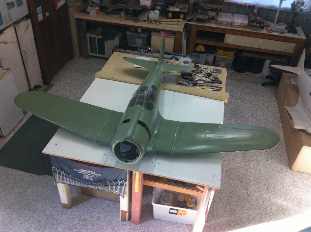

This is one of the early airframes out of the mold which is destined to be painted at the same time as my flyer and will become a static display. It will end up hanging up either in my workshop or my hangar.
Cheers
Mick
The bench it is sitting on is made up of 2 standard house doors.
This is one of the early airframes out of the mold which is destined to be painted at the same time as my flyer and will become a static display. It will end up hanging up either in my workshop or my hangar.
Cheers
Mick
02-20-2014, 01:56 PM
#383
 02-20-2014, 03:47 PM
#385
02-24-2014, 05:40 AM
#386
Some more progress.............
As this Boomerang was originally designed to be electric powered and I am now fitting a DLE 111, I have to assess things keeping in mind the level of vibration will be more than what was originally planned for. I have had some insight into this with my P-47 that was originally built by RAP ( Richard And Patti ) as electric but I have now fitted a DLE 55 to it.
The elevators of the Boomerang had been fitted with only 2 hinges on each half in scale locations, plus being carried in some part by the torque rod that drives them. To ensure my peace of mind I have fitted an extra hinge point to each elevator.
RAP use a hinge created using fibreglass board, brass tube and a pin along the length of the hinge line. This is all drawn in CAD, cut on their CNC machine and all locks together when assembled to ensure it all lines up. I do not have any CAD skills or a CNC machine so all I had to get all this to line up was some really careful measuring, hand cutting and drilling.
First up I had to add a support in the elevator to take the hinge pin. Starting with cutting a new opening in the leading edge of the elevator. Then I cut a piece of ply to support the brass tube that carries the hinge pin. Next glue it in place ensuring it was aligned accurately.

Then cut a piece of fibreglass board to the required shape and fit it to the tailplane. It is keyed into the traling edge of the tailplane. Then with that piece fitted, mark & drill it to take the hinge pin. It is the inboard hinge that I have added.
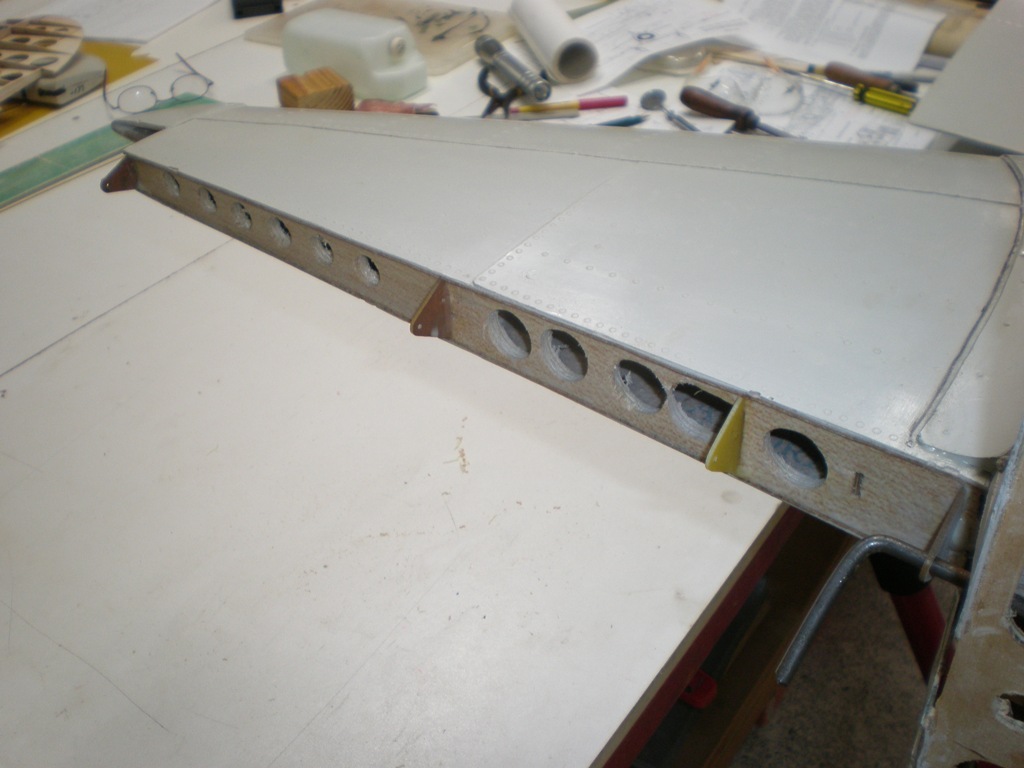
And a close up of the added hinge tab ( and yes I will remove that dribble of epoxy - every bit of weight counts!!! ) These will later have brass tube inserted to act as bushes.

Another pic to give proportion to the elevator. Thats a 300mm or 12 inch rule. It is the inboard hinge that I have added.

With all that done & the epoxy set it was time to hold my breath and try to insert the hinge pins.............


It worked!!!! The pin went in no problems. You can see the ends of the ( untrimmed ) pins sticking out of the tips of the elevators.
That's it for now.
Mick
As this Boomerang was originally designed to be electric powered and I am now fitting a DLE 111, I have to assess things keeping in mind the level of vibration will be more than what was originally planned for. I have had some insight into this with my P-47 that was originally built by RAP ( Richard And Patti ) as electric but I have now fitted a DLE 55 to it.
The elevators of the Boomerang had been fitted with only 2 hinges on each half in scale locations, plus being carried in some part by the torque rod that drives them. To ensure my peace of mind I have fitted an extra hinge point to each elevator.
RAP use a hinge created using fibreglass board, brass tube and a pin along the length of the hinge line. This is all drawn in CAD, cut on their CNC machine and all locks together when assembled to ensure it all lines up. I do not have any CAD skills or a CNC machine so all I had to get all this to line up was some really careful measuring, hand cutting and drilling.
First up I had to add a support in the elevator to take the hinge pin. Starting with cutting a new opening in the leading edge of the elevator. Then I cut a piece of ply to support the brass tube that carries the hinge pin. Next glue it in place ensuring it was aligned accurately.
Then cut a piece of fibreglass board to the required shape and fit it to the tailplane. It is keyed into the traling edge of the tailplane. Then with that piece fitted, mark & drill it to take the hinge pin. It is the inboard hinge that I have added.
And a close up of the added hinge tab ( and yes I will remove that dribble of epoxy - every bit of weight counts!!! ) These will later have brass tube inserted to act as bushes.
Another pic to give proportion to the elevator. Thats a 300mm or 12 inch rule. It is the inboard hinge that I have added.
With all that done & the epoxy set it was time to hold my breath and try to insert the hinge pins.............
It worked!!!! The pin went in no problems. You can see the ends of the ( untrimmed ) pins sticking out of the tips of the elevators.
That's it for now.
Mick
Last edited by BOLTMAN; 02-24-2014 at 07:19 AM.
02-26-2014, 08:40 PM
#388
The Boomerang's retracts turned up today.
Made by "Custom Retracts" right here in OZ specially for this project. It's good to be able to use an Aussie product in the Aussie Fighter.
As there are no plans for this model, I have had the units made and after they are installed I will measure up and confirm the exact length for the legs. Al at Custom Retracts kindly sent me a "dummy" oleo leg to use in working out the positioning and mounting angles of the units.


Mick
Made by "Custom Retracts" right here in OZ specially for this project. It's good to be able to use an Aussie product in the Aussie Fighter.
As there are no plans for this model, I have had the units made and after they are installed I will measure up and confirm the exact length for the legs. Al at Custom Retracts kindly sent me a "dummy" oleo leg to use in working out the positioning and mounting angles of the units.
Mick
Last edited by BOLTMAN; 02-27-2014 at 02:27 AM.
02-27-2014, 01:53 AM
#389


Join Date: Dec 2003
Location: BundabergQueensland, AUSTRALIA
Posts: 142
Likes: 0
Received 0 Likes
on
0 Posts
Hi there B.Man
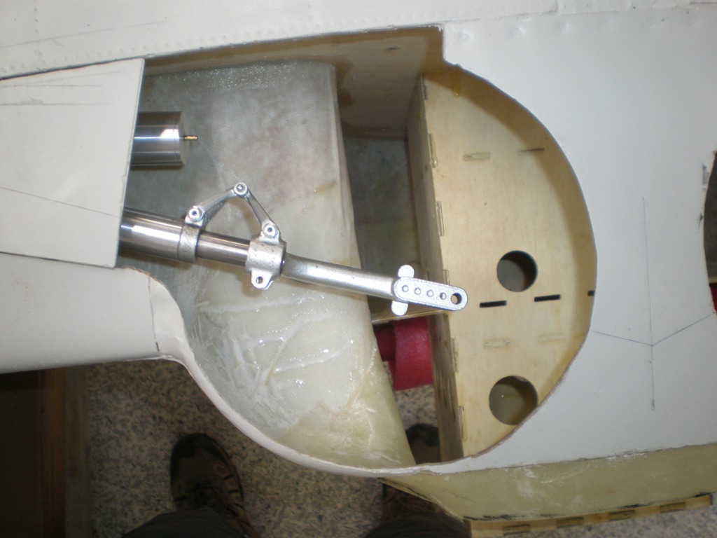
Here is a pic of the Robart gear in the 4.5 scale Boomerang wing center section. Your Custom Retracts look a much more solid construction so should cope with the weight better which was the big concern.
Will they fit into the LE though? They look like they will need a wider bearer spacing which might make it a tight fit into the LE.
If you want to have a play with the fit in Rhino 3D before you go cutting holes I can send you the 3D drawing of just the wing section which should be small enough to email - DropBox?? If you could send a dimensioned sketch of the Custom gear I could model it in 3D for you as well.
Looking good
RAP
02-27-2014, 03:42 AM
#390
Hi RAP,
The main body of these retracts is the same extrusion as the Mustang retracts that I have. Most of the extra bulk of these units versus the Robarts is behind the pivot point for the leg and with the tapered profile, fitting into the leading edge should not be a problem. With that extra bulk behind the pivot point it will end up a tight squeeze between the rear mounting rail and the full depth ply spar, but I reckon it will fit.
From all the measuring I have done it looks like I will be able to leave part of the existing mounting rails in place to use to locate the unit and then add new mounts around what is left of the original rails.
It's all part of the fun!
Cheers
Mick
03-04-2014, 08:03 PM
#391
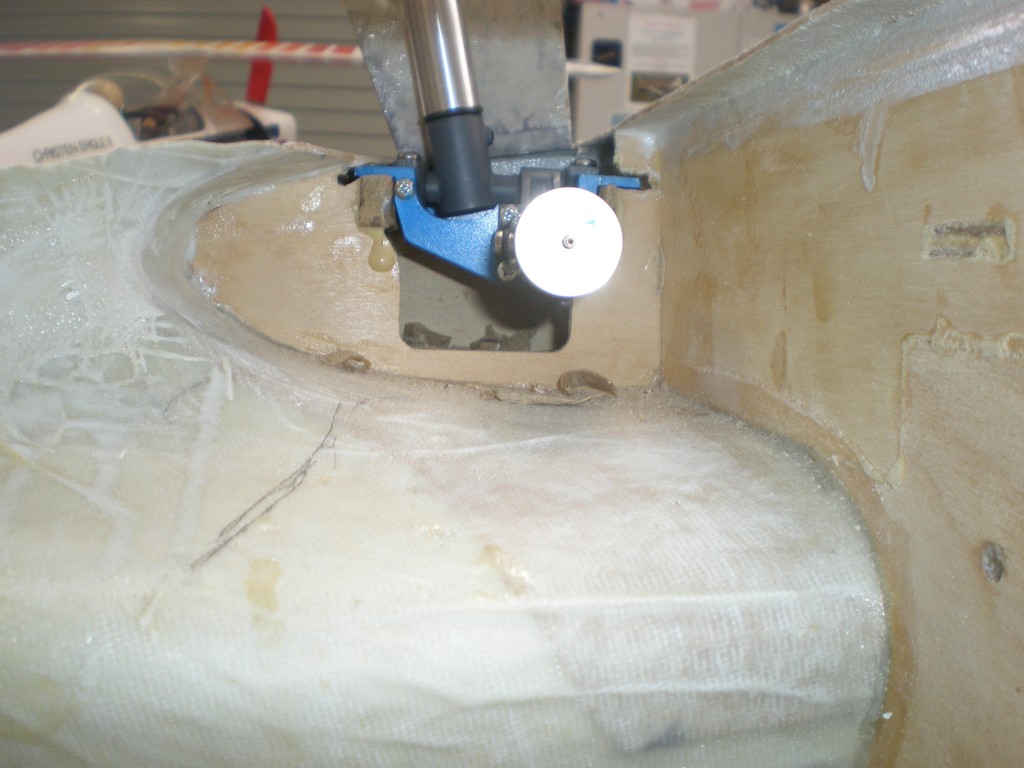
After a fair bit of whittling away at the existing retract rails I have one of the new retracts located. The original retract rails were set 52mm apart.

The new retracts required the rails to be 64mm apart. After some measuring I worked out that removing 8mm from the back rails and 4mm off the front rail, should put the pivot point where required. You can see in the pic below there is not much left of the rear rail, and the front rail is also does not have enough left. I plan on using what is left of these rails as locating guides only & will build new structures around them. Note that at this stage the leg is about 25mm longer than required.


The retract will also need to move deeper into the wing, as at the moment the wheels will sit below the bottom wing surface when retracted. The Boomerang undercarriage, while similar to a Texan, actually has lower doors attached opposite to the offset portion of the leg, so this height will need to be correct. There is plenty of room to move into the wing about 12-20mm as required.

Once this height is correct, I will set about matching it on the other side. Then start building the new load bearing structure around what is left of the original rails.
The new retracts required the rails to be 64mm apart. After some measuring I worked out that removing 8mm from the back rails and 4mm off the front rail, should put the pivot point where required. You can see in the pic below there is not much left of the rear rail, and the front rail is also does not have enough left. I plan on using what is left of these rails as locating guides only & will build new structures around them. Note that at this stage the leg is about 25mm longer than required.
The retract will also need to move deeper into the wing, as at the moment the wheels will sit below the bottom wing surface when retracted. The Boomerang undercarriage, while similar to a Texan, actually has lower doors attached opposite to the offset portion of the leg, so this height will need to be correct. There is plenty of room to move into the wing about 12-20mm as required.
Once this height is correct, I will set about matching it on the other side. Then start building the new load bearing structure around what is left of the original rails.
03-27-2014, 05:31 AM
#393
Hi Patti,
The ribs will fit OK once I do some cleaning up of the inside surface of the wing, need to get rid of some lumps & bumps on the inside skin. I have not had the chance to do much lately, been busy with the full size stuff. I am guessing with this weather you guys are getting more time in the workshop?
As for pics, well this is the best I can do - I recently bought this pair -


Added to the one I already had -

This takes my collection of 1/72 scale Boomerangs to three -

Damn! These pics show how badly I need to dust out the display cabinets!!!!
The ribs will fit OK once I do some cleaning up of the inside surface of the wing, need to get rid of some lumps & bumps on the inside skin. I have not had the chance to do much lately, been busy with the full size stuff. I am guessing with this weather you guys are getting more time in the workshop?
As for pics, well this is the best I can do - I recently bought this pair -
Added to the one I already had -
This takes my collection of 1/72 scale Boomerangs to three -
Damn! These pics show how badly I need to dust out the display cabinets!!!!
Last edited by BOLTMAN; 03-27-2014 at 05:35 AM.
02-07-2015, 05:16 AM
#398

Hi Guys, I�m new in this Forum.
I�m from Germany and building also a CAC Boomerang , my second. The sice is 1:3,5 wingspan 320 cm, weight under 25 kg with a Moki 215 Radial.
If you want i can Show some Pictures.
I�m also in "warbirdforum" in Europe, don�t know if it is worldwide?
I�m from Germany and building also a CAC Boomerang , my second. The sice is 1:3,5 wingspan 320 cm, weight under 25 kg with a Moki 215 Radial.
If you want i can Show some Pictures.
I�m also in "warbirdforum" in Europe, don�t know if it is worldwide?
 02-07-2015, 07:58 PM
#400
HI Warbirdcharly,
All Boomerangs are welcome here. I too would love to see some of your pictures.
My Boomerang is on hold due to working on another P-47 and now it looks like I will be going on to a Corsair next so the Bommerang will continue to wait patiently.......
Cheers!
All Boomerangs are welcome here. I too would love to see some of your pictures.
My Boomerang is on hold due to working on another P-47 and now it looks like I will be going on to a Corsair next so the Bommerang will continue to wait patiently.......
Cheers!